steering wheel HONDA CR-V 1998 RD1-RD3 / 1.G Service Manual
[x] Cancel search | Manufacturer: HONDA, Model Year: 1998, Model line: CR-V, Model: HONDA CR-V 1998 RD1-RD3 / 1.GPages: 1395, PDF Size: 35.62 MB
Page 1389 of 1395
Gable Reel
Replacement (cont'dl
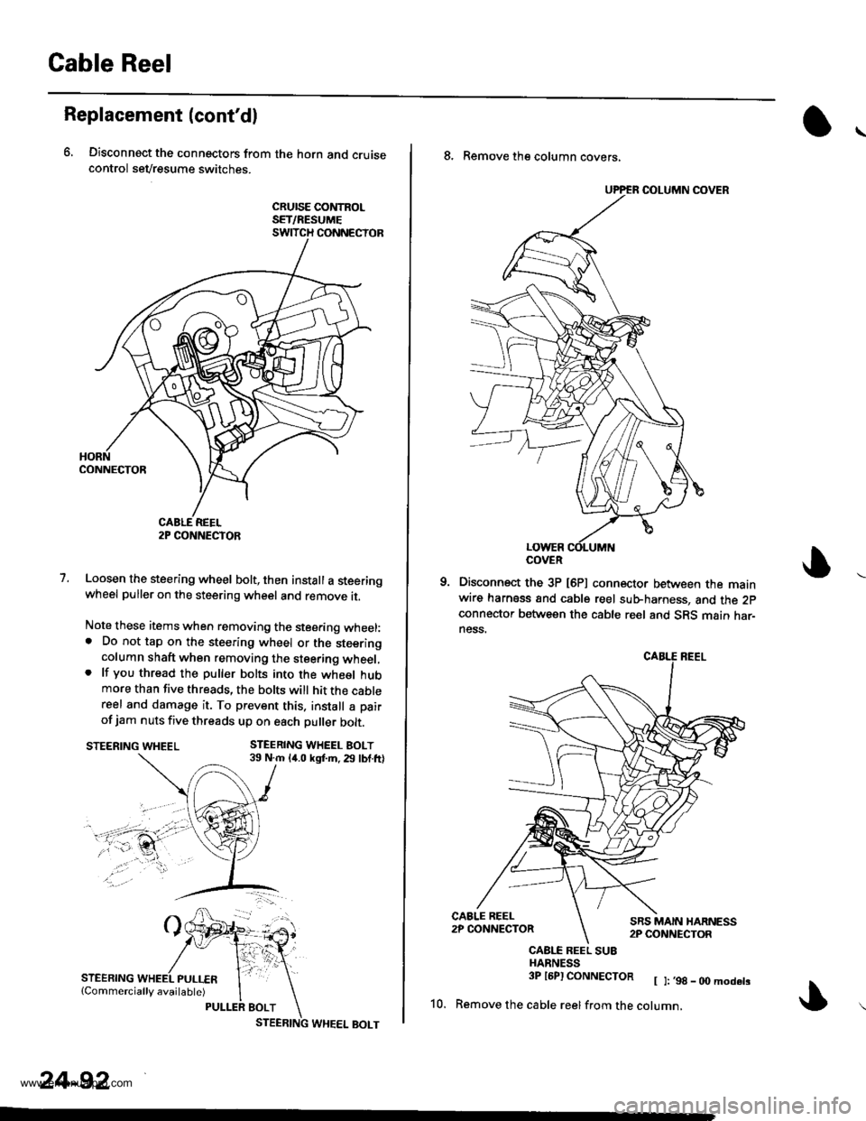
6, Disconnect the connectors from the horn and cruisecontrol sevresume switches.
cRursE coNtRoLSET/RESUMESWITCH CONNECTOR
1.Loosen the steering wheel bolt, then install a steeringwheel puller on the steering wheel and remove it.
Note these items when removing the stee.ing wheel:. Do not tap on the steering wheel or the steeringcolumn shaft when removing the steering wheel,. lf you thread the puller bolts into the wheel hubmore than five threads, the bolts will hit the cablereel and damage it. To prevent this. install a pair
of jam nuts five threads up on each puller bolt.
STEERING WHEEL BOLT39 N.m 14.0 kgf.m. 29 lbf.ftlSTEERING WHEEL
STEERING
2P CONNECTOR
24-92
8. Remove the column covers,
Disconnect the 3P [6P] connector between the mainwire harness and cable reel sub-harness, and the 2pconnector between the cable reel and SRS main har-ness.
CAALE REEL SU8HARNESS3P l6Pl CONNECTOR [ ]:,98_00modets
10. Remove the cable reelfrom the cotumn,
COVER
www.emanualpro.com
Page 1390 of 1395
)o
NOTE:
. Before installing the steering wheel, the front
wheels should be aligned straight ahead.
. Be sure to install the harness wires so that they
are not pinched or interfering with other parts.
. After reassemblv, confirm that the wheels are
still turned straight ahead and that the steering
wheel spoke angle is correct (road test). lf minor
spoke angle adjustment is necessary, do so only
by adjusting the tie-rods, not by removing and
repositioning the steering wheel,
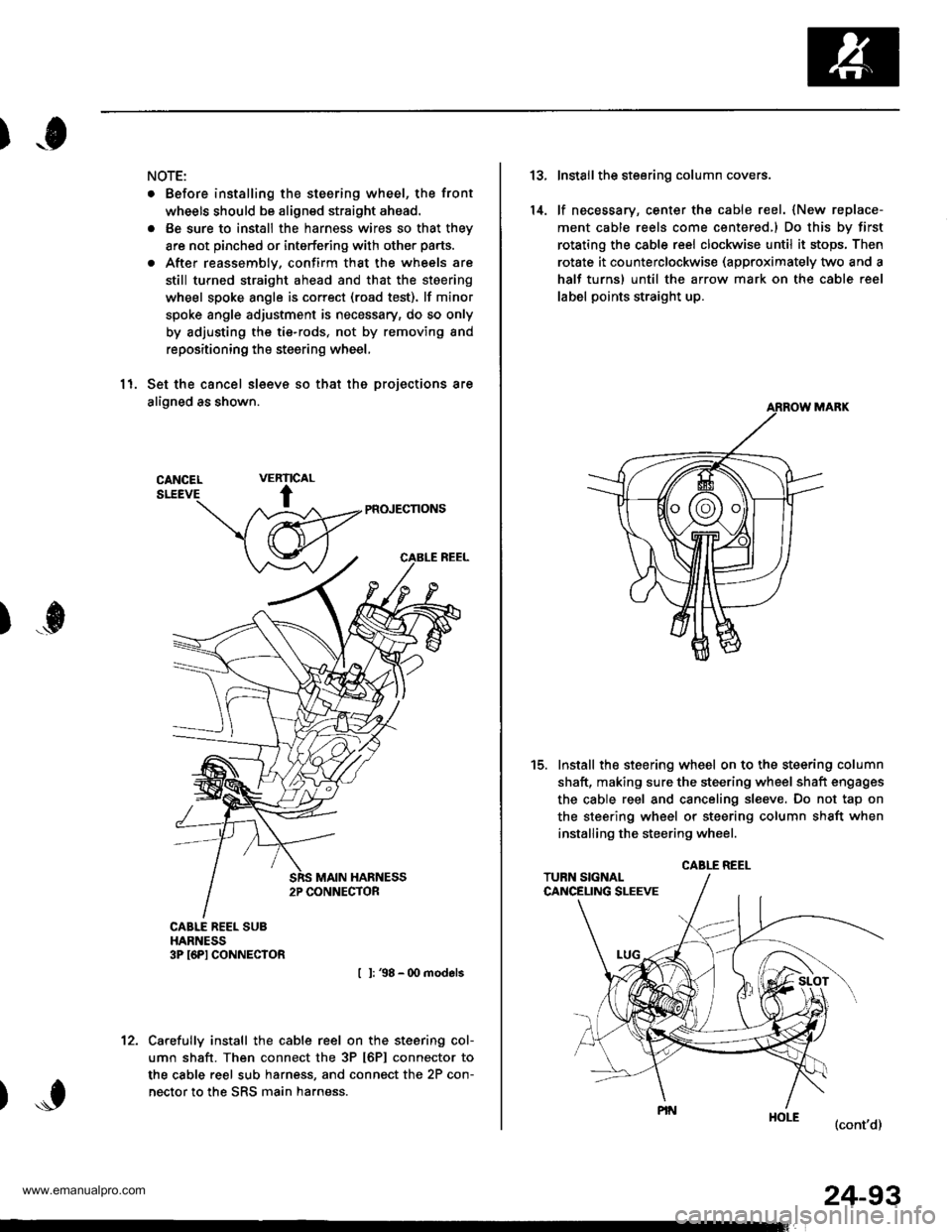
11. Set the cancel sleeve so that the projections are
aligned as shown.
PR(NECNONS
I l: 38 - 00 models
Carefully install the cable reel on the steering col-
umn shaft. Then connect the 3P t6Pl connector to
the cable reel sub harness, and connect the 2P con-
nector to the SRS main harness.
RIC
t
VEAL
)...0
't2.
24-93
13.
14.
Install the steering column covers.
lf necessary, center the cable reel. {New replace-
ment cable reels come centered,l Do this by first
rotating the csble reel clockwise until it stops, Then
rotate it counterclockwise (approximately two and a
half turns) until the arrow mark on the cable reel
label points straight up.
Install the steering wheel on to the steering column
shaft, making sure the steering wheel shaft engages
the cable reel and canceling sl€eve. Do not tap on
the steering wheel or steering column shaft when
installing the steering wheel.
(cont'd)
t5.
CABLE REEL
www.emanualpro.com
Page 1391 of 1395
Cable Reel
16.
Replacement (cont'dl
11.
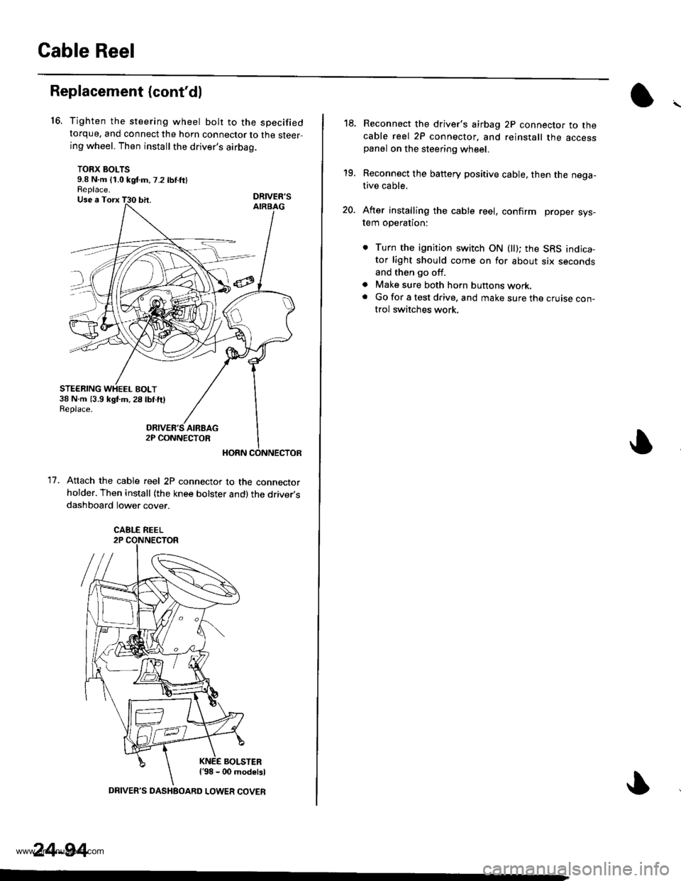
Tighten the steering wheel bolt to the specifiedtorque, and connect the horn connector to the steering wheel. Then install the driver's airbag.
TORX BOLTS9.8 N.m (1.0 kgd.m,7.2 lbnftlReplace.DRIVER'S
Attach the cable reel 2P connector to the connectorholder. Then install (the knee bolster and)the driver,sdashboard lower cover.
BOLSTERl'98 - 00 modalsl
STEERING WHEEL BOLT38 N.m (3.9 kgl.m,28lbf.ftlReplace.
CABLE REEL
24-94
DRIVER'S DASHEOARD LOWER COVER
19.
20.
Reconnect the driver's airbag 2P connector to thecable reel 2P connector, and reinstall the accesspanel on the steering wheel.
Reconnect the battery positive cable, then the nega-tive cable.
After installing the cable reel, confirm proper sys-tem operation:
. Turn the ignition switch ON (ll); the SRS indica-tor light should come on for about six secondsand then go off.
a Make sure both horn buttons work.. Go for a test drive. and make sure the cruise con-trol switches work.
www.emanualpro.com
Page 1392 of 1395
SRS Unit
).0Replacement
CAUTION:
. Before disconnecting any part of the SRS wire har-
nesg, disconnect the airbag connoctors (and soat beh
tensioner connectorsl.
. During installation or replacament, do not bump(impact wrench, hammer etc.) the area near the SRS
unit.
Do not damage the SFS unit terminalg or connsc-
lors.
Do not disassemble the SRS unit it has no saryice-
able parts,
Store the SRS unit in a clean, dry area.
Do not use any SRS unit which has been subiected
to water damage or shows signs ot being dropped orimproperly handlgd, such as dents, cracks or defor-
mation.
Disconnect the battery negative cable, then discon-
nect the positive cable from the battery, andwaitat
least three minutes.
Disconnect the airbag connectors (and seat belt ten-
sioner connectors). (When disconnected, the airbag
and seat belt tensioner connectors are automatical-
ly shorted.)
Driver's Side:
. Remove the access panel from the steering
wheel, then disconnect the 2P connector
between the driver's airbag and cable reel (see
page 24-231.
Front Passenger's Side:. Disconnect the 2P connector between the frontpassenger's airbag and SRS main harness (see
page 24-231.
Soat Beh Tensionor ('98 - 00 modelsr:. Remove the left and right center pillar lower trimpanels (see section 20).
. Disconnect the seat belt tensioner 2P connectors
from the left side wire harness (driver's side) and
the right wire harness (front passenger's side)(see page 24'231.
2.
a
a
'1.
)
)o
24-95
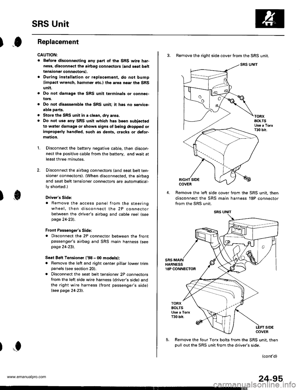
3. Remove the right side cover from the SRS unit.
SRS UNIT
TORXAOLTSUse a TorxT30 bir.
COVER
Remove the left slde cover from the SRS unit. then
disconnect the SRS main harness 18P connector
from the SRS unit.
sRsHARNESS18P CONNECTOR
TORXBOLTSUs€ a TorxT30 bir.
stoECOVER
Remove the four Torx bolts from the SRS unit. then
oull out the SRS unit from the driver's side.
(cont'd)
www.emanualpro.com
Page 1393 of 1395
SRS Unit
Replacement (cont'dl
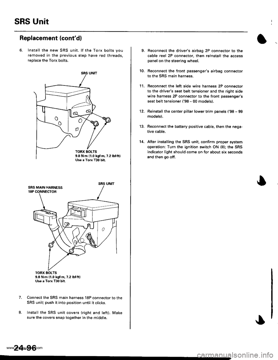
6. lnstall the new SRS unit. lf the Torx bolts you
removed in the previous step have red threads,
replace the Torx bolts.
TORX BOLTS9.8 N.m 11.0 kgf.m,7.2 lbtft)Uso a Torx T30 bit.
Connect the SRS main harness l8P connector to the
SRS uniu push it into position until it clicks.
Install the SRS unit covers (right and left). Make
sure the covers snap together in the middle.
7.
8.
TORX BOLTS9.8 N.m {1.0 kgf.m, ?.2Use . Torx T30 bh,
SRS UNIT
24-96
-
9. Reconnect the driver's aibag 2P connector to the
cable reel 2P connector, then reinstall the access
panel on the steering wheel.
Reconnect the front passenger's airbag connector
to the SRS main harness.
Reconnect the left side wire harness 2P connector
to the driver's seat belt tensioner and the right side
wire harness 2P connector to the front passenger's
seat belt tensioner ('98 - 00 models).
Reinstall the center pillar lower trim panels {'98 - 99
modelsl.
Reconnect the battery positive cable, then the nega-
tive cable.
After installing the SRS unit, confirm proper system
operation: Turn the ignition switch ON (ll); the SRS
indicator light should come on for about six seconds
and then go off,
10.
1't.
12.
13.
14.
www.emanualpro.com