HONDA CR-V 1998 RD1-RD3 / 1.G Workshop Manual
Manufacturer: HONDA, Model Year: 1998, Model line: CR-V, Model: HONDA CR-V 1998 RD1-RD3 / 1.GPages: 1395, PDF Size: 35.62 MB
Page 501 of 1395
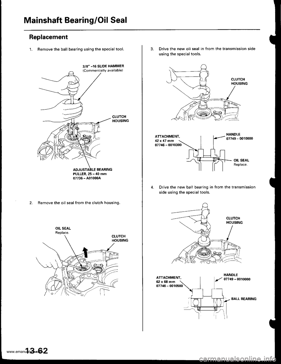
Mainshaft Bearing/Oil Seal
Replacement
1. Remove the ball bearing using the specialtool.
3/8" -16 SLIDE HAMMER(Commercially available)
PULLER.25 - ,10 mm07736 - A01000A
2. Remove the oil seal from the clutch housing.
13-62
BALL BEARING
3. Drive the new oil seal in from the transmission side
using the special tools.
ATTACHMENT,12x 17 .nfi07746 - 0010300
Drive the new bali bearing in from the transmission
side using the special tools.
ATTACHMENT.62x68mm07746 - 0010500
www.emanualpro.com
Page 502 of 1395
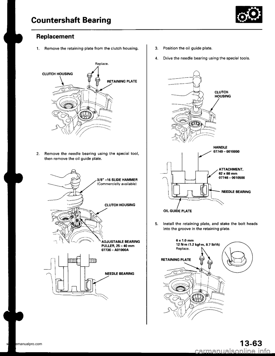
Gountershaft Bearing
Replacement
1. Remove the retaining plate from the clutch housing.
CLUTCH HOUSING
HETAINING PLATE
Remove the needle bearing using the special tool,
then remove the oil guide plate.
Replace.
3/8" -16 SLIDE HAMMER(Commercially available)
CLUTCH TIOUSING
^'ADJUSTABI.f BEARINGPULLER,25 - 40 mm07736 - A01(x)04
NEEDLE BEARING
Position the oil guide plate.
Drive the needle bearing using the special tools.
ATTACHMENT,62x88mm07746- 0t!105q)
NEEDII AEARING
Install the retaining plate, and stake the bolt heads
into the groove in the retaining plate
6x1.0mm12 N.m (1.2 kgt m,8.7 lbtftl
13-63
www.emanualpro.com
Page 503 of 1395
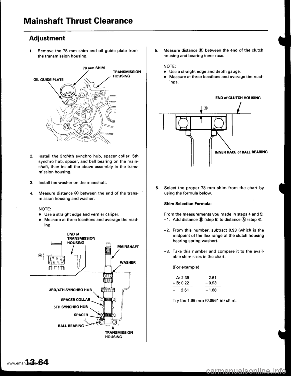
Mainshaft Thrust Clearance
Adjustment
l. Remove the 78 mm shim
the transmission housing.
4.
and oil guide plate from
Install the 3rd/4th synchro hub, spacer collar, sth
synchro hub, spacer, and ball bearing on the main-
shaft. then install the above assembly in the trans-
mission housing.
lnstallthe washer on the mainshaft.
Measure distance @ between the end of the trans-
mission housing and washer,
NOTE:
. Use a straight edge and vernier caliper.
. Measure at three locations and average the read-
Ing.
END otTRANSMISSION
MAINSHAFT
WASHER
3RD/4TH SYNCHRO HUB
SPACER COLLAR
sTH SYNCHRO HUB
SPACER
78 mm SHIM
13-64
BALL BEARING
5, Measure distance @ between the end of the clutch
housing and bearing inner race.
NOTE:
. Use a straight edge and depth gauge.
. Measure at three locations and avorage the read-
Ings.
END ot CLUTCH HOUSING
BEARING
Select the proper 78 mm shim from the chan by
using the formula below.
Shim S€lection Formula:
From the measurements you made in steps 4 and 5:-1. Add distance @ (step 5) to distance @ (step 4).
-2. From this number. subtract 0.93 (which is the
midpoint of the flex range of the clutch housing
bearing spring washer).
-3. Take this number and compare it to the avail-
able shim sizes in the chart.
(For example)
A: 2.39 2.61
+ Bi O.22 - 0.93
= 2.61= 1.68
Try the 1.68 mm (0.0661 in) shim.
www.emanualpro.com
Page 504 of 1395
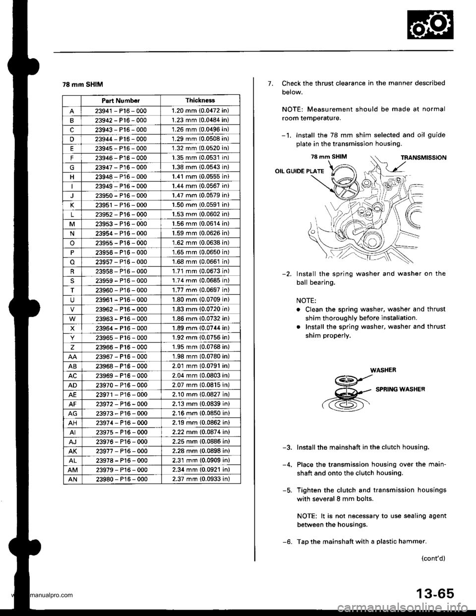
78 mm SHIM
Part NumborThickness
23941 - P16 - 0001.20 mm (0.0472 in)
23942-P16-0001.23 mm (0.0484 in)
c23943-P16-000'1.26 mm (0.0496 in)
u23944-Pt6-0001.29 mm (0.0508 in)
23945-P16-0001.32 mm (0.0520n)
F23946- P16 - 0001.35 mm (0.0531n)
G23947-P16-0001.38 mm {0.0543n)
H23948-P16-0001.41 mm (0.0555n)
23949-P16-0001.44 mm (0.0567 in)
23950-P16-0001.47 mm (0.0579 in)
K23951 - P16 - 0001.50 mm {0.0591 in}
L23952-Pl6-0001.53 mm (0.0602 in)
M23953-P16-0001.56 mm (0.0614 in)
N23954-P16-0001.59 mm (0.0626 in)
o23955-P15-0001.62 mm (0.0638 in)
23956 - P16 - 0001.65 mm (0.0650 in)
23957-P16-0001.68 mm (0.066't in)
23958- P16 - 0001.71 mm (0.0673 in)
23959-P16-0001.74 mm {0.0685 in)
T23960-P16-0001.77 mm {0.0697 inl
23961 - P16 - 0001.80 mm (0.0709 in)
23962-P16-0001.83 mm (0.0720 in)
23963-P16-000'1.86 mm (0.0732 in)
X23964-P16-0001.89 mm (0.0744 in)
23965-P16-0001.92 mm (0.0756 in)
z23966-Pl6-0001.95 mm (0.0768 in)
23967-Pl6-0001.98 mm (0.0780 in)
AB23968-P16-0002.01 mm (0.0791 in)
23969-Pl6-0002.04 mm (0.0803 in)
AD23970 - Pl6-0002.07 mm {0.0815 in)
AE23971 - P16 - 0002.10 mm {0.0827 in}
23972-P16-0002.13 mm (0.0839 in)
23973-P16-0002.16 mm (0.0850 in)
AH23974-P16-0002.19 mm (0.0862 in)
AI23975-P16-0002.22 mm 10.087 4 inl
AJ23976-Pl6-0002.25 mm {0.0886 in}
AK23977-P16-0002.28 mm {0.0898 in)
23978-Pl6-0002.31 mm (0.0909 in)
23979-Pl6-0002.34 mm (0.0921 in)
AN23980-P16-0002.37 mm (0.0933 in)
7, Check the thrust clearance in the manner described
Delow.
NOTE: Measurement should be made at normal
room temperature.
-1. Install the 78 mm shim selected and oil guide
plate in the transmission housing.
78 mm SHIM
OIL GUIDE PLATE
Install the spring washer and washer on the
ball bearing.
NOTE:
. Clean the spring washer, washer and thrust
shim thoroughly before installation.
. Install the spring washer, washer and thrust
shim properly.
WASHER
g
,-g
SPRTNG*ASHER
Install the mainshaft in the clutch housing.
Place the transmission housing over the main-
shaft and onto the clutch housing.
Tighten the clutch and transmission housings
with several 8 mm bolts.
NOTE: lt is not necessary to use sealing agent
between the housings.
Tap the mainshaft with a plastic hammer.
-2.
-5.
(cont'd)
13-65
www.emanualpro.com
Page 505 of 1395
Mainshaft Thrust Clearance
Adjustment (cont'dl
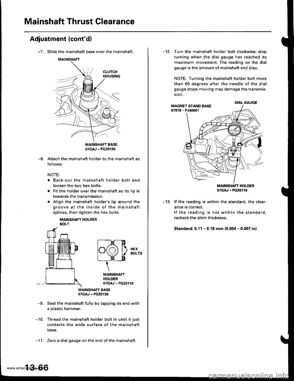
-7. Slide the mainshaft base over the mainshaft.
Attach the mainshaft holder to the mainshaft as
follows:
NOTE:
. Back-out the mainshaft holder bolt and
loosen the two hex bolts.
. Fit the holder over the mainshaft so its lip is
towards the transmission.
. Align the mainshaft holder's lip around the
groove at the inside of the mainshaft
splines, then tighten the hex bolts.
MAINSHAFT HOLDERBOLT
MAINSHAFT EASE07GAJ - PG20130
-9. Seat the mainshaft fully by tapping its end with
a plastic hammer.
-10. Thread the mainshaft holder bolt in until it just
contacts the wide surface of the mainshaft
base.
07GAJ - PG20130
-8.
t--E-Hlf\f,A l\. xex
l"\y I aors
t____=__)"n-____"8
\
MAINSHAFTHOLDER07GAJ - PG20110
- 11. Zero a dial gauge onthe end ofthe mainshait.
-12. Turn the mainshaft holder bolt clockwise; stop
turning when the dial gauge has reached its
maximum movement, The reading on the dial
gauge is the amount of mainshaft end play.
NOTE: Turning the mainshaft holder bolt more
than 60 degrees after the needle of the dial
gauge stops moving may damage the transmis-
sion.
MAINSHAFT HOLDER07cru - PG20110
-13. lf the reading is within the standard, the clear-
ance rs correct.
lf the reading is not within the standard,
recheck the shim thickness.
Standard: 0.11 - 0.18 mm (0.00i1- 0.007 inl
DIAL GAUGEMAGNET STAND AASE07979 - PJ40001
www.emanualpro.com
Page 506 of 1395
Transmission Assembly
Reassembly
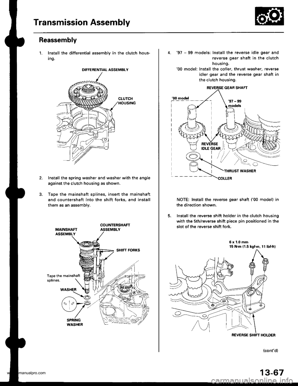
1. Install the differential assembly in the clutch hous-
Ing.
Install the spring washer and washer with the angle
against the clutch housing as shown.
Tape the mainshaft splines. insert the mainshaft
and countershaft into the shift forks, and install
them as an assemblv.
Tape the mainshattsplines.
DIFFERENTIAL ASSEMBLY
4. '97 - 99 models: Install the reverse idle gaar and
reverse gear shaft in the clutch
housing.'00 model: Install the coller, thrust washer, reverse
idler gear and the reverse gear shaft in
the clutch housing.
THRUST WASHER
COLLER
NOTE: Install the reverse gear shaft ('00 model) in
the direction shown.
5. Install the reverse shift holder in the clutch housing
with the sth/reverse shift piece pin positioned in the
slot of the reverse shift fork.
5x1.0mm15 N'm 11.5 kgt.m, 11 lbf.ftl
model
REVERSE SHIFT HOLDER
(cont'd)
13-67
www.emanualpro.com
Page 507 of 1395
Transmission Assembly
Reassembly (cont'dl
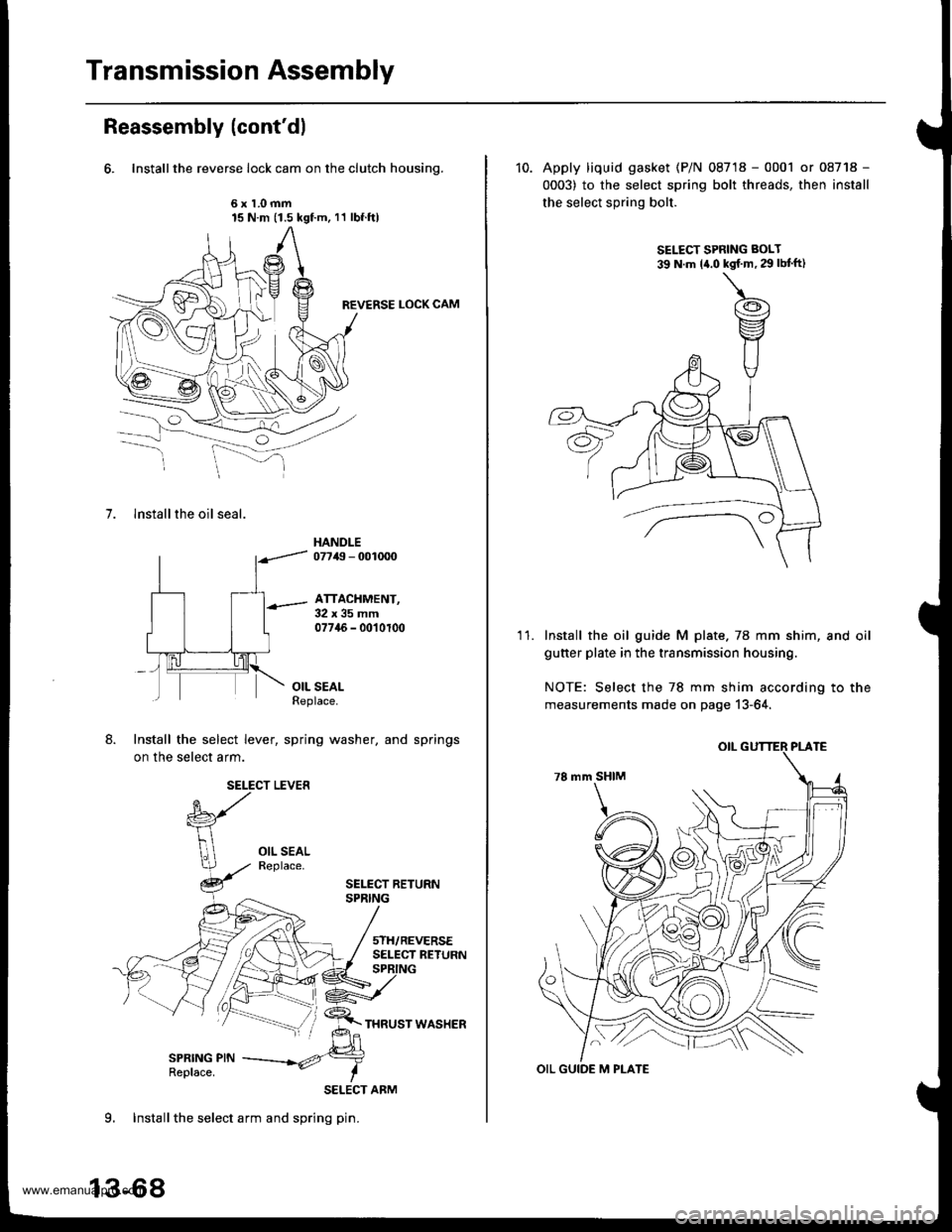
6. Installthe reverse lock cam on the clutch housing.
6x1.0mm15 N.m (1.5 kgf.m, 11 lbf.ftl
REVERSE LOCK CAM
7. lnstall the oil seal.
HANDLE07749 - 001mO
ATTACHMENT,32x35mm07745 - 0010100
OIL SEALReplace.
Install the select lever, spring washer, and springs
on the select arm.
SELECT LEVER
SELECT BETURNSPRING
5TH/REVERSESELECT RETURN
SPRING PINReplace.
SELECT ARM
9. Installthe select arm and spring pin.
13-68
10. Apply liquid gasket (P/N 08718 - 0001 or 08718 -
0003) to the select spring bolt threads, then install
the select spring bolt.
SELECT SPRING BOLT
39 N.m la.o kgf'm,29lbtft)
'I 1.Install the oil guide M plate.78 mm shim, and oil
guner plate in the transmission housing.
NOTE: Select the 78 mm shim according to the
measurements made on page 13-64,
OIL GUIDE M PLATE
www.emanualpro.com
Page 508 of 1395
12. Apply liquid gasket to the surface of the transmis-
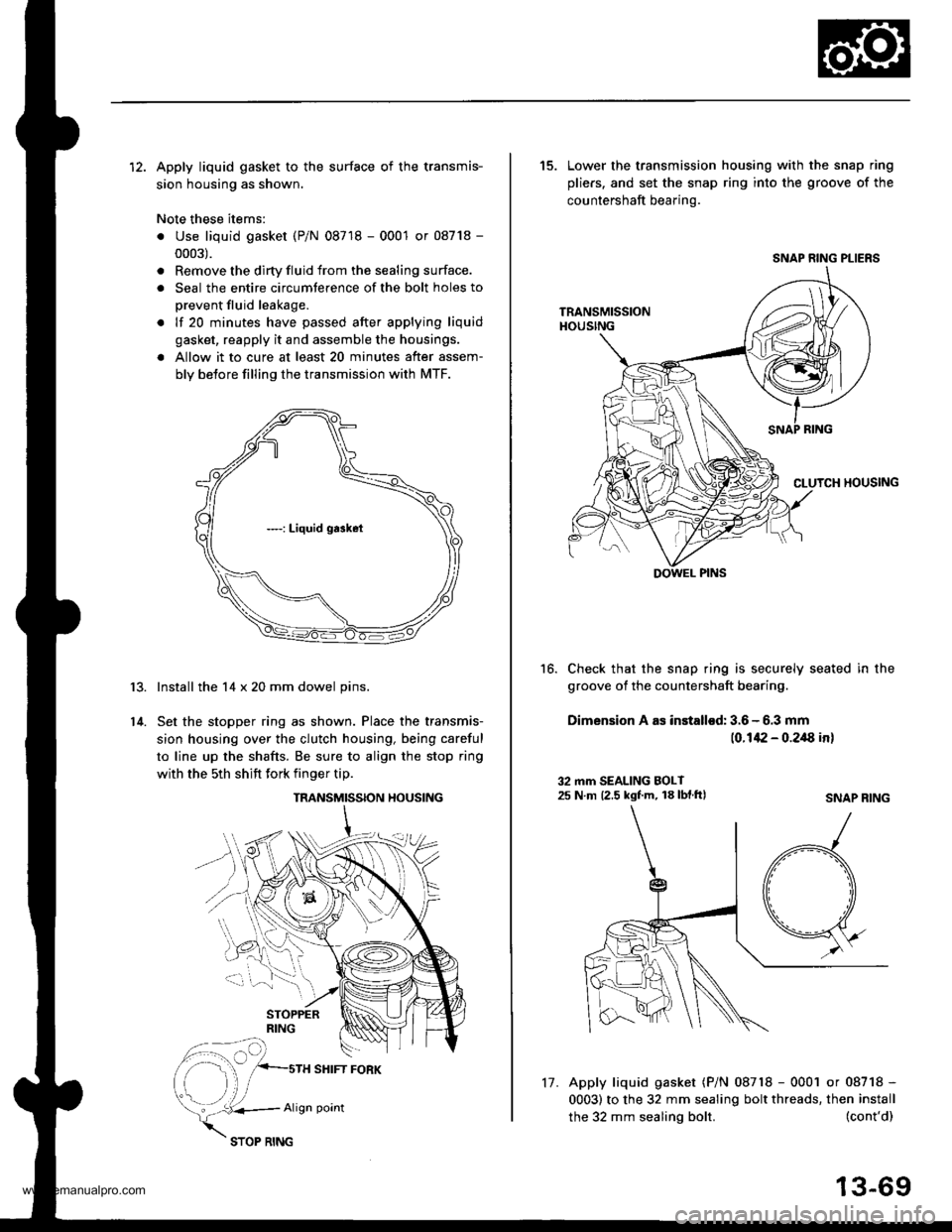
sion housing as shown.
Note these items:
. Use liquid gasket (P/N 08718 - 0001 or 08718 -
0003).
. Remove the dirty fluid from the sealing surface.
. Seal the entire circumterence of the bolt holes to
prevent fluid leakage.
. lf 20 minutes have passed after applying liquid
gasket, reapply it and assemble the housings.
a Allow it to cure at least 20 minutes after assem-
bly betore filling the transmission with MTF.
Install the 14 x 20 mm dowel pins.
Set the stopper ring as shown. Place the transmis-
sion housing over the clutch housing, being careful
to line up the shafts. Be sure to align the stop ring
with the 5th shift fork finger tip.
r3.
14.
TRANSMISSION HOUSING
SHIFT FORK
vk..*,
Align point
17.
the 32 mm sealing bolt.
15. Lower the transmission housing with the snap ring
pliers. and set the snap ring into the groove of the
countershaft bearing.
Check that the snap ring is securely seated in the
groove of the countershaft bearing.
Dimension A as installod: 3.6 - 6.3 mm
(0.142 - 0.2/8 in)
16.
32 mm SEALING BOLT25 N m 12.5 kgf.m, 18 lbf.ftlSNAP RING
(cont'd)
13-69
Apply liquid gasket (P/N 08718 - 0001 or 08718 -
0003) to the 32 mm sealing bolt threads, then install
SNAP RING PLIERS
DOWEL PINS
www.emanualpro.com
Page 509 of 1395
Transmission Assembly
Reassembly lcont'd)
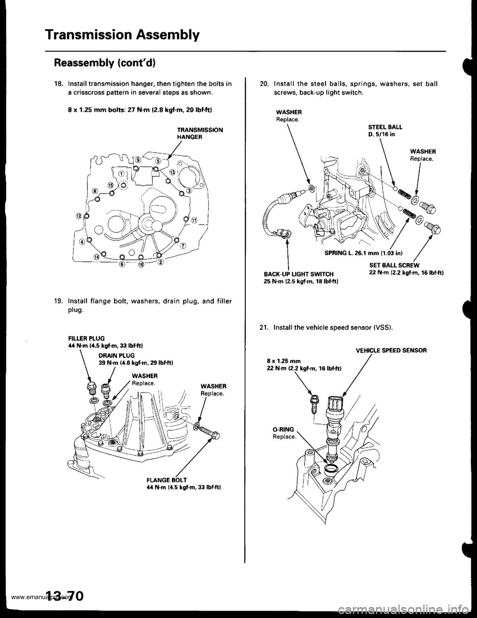
18. Installtransmission hanger, then tighten the bolts in
a crisscross pattern in several steps as shown.
8 x 1.25 mm bolis: 27 N.m 12.8 kgf.m,20 lbf'ft}
TRANSMISSIONHANGER
19.Install flange bolt,
plug.
washers, drain plug. and filler
FILLER PLUG4,r N.m (a.5 kgl.m,33lbtftl
DRAIN PLUG39 N.m {4.0 kg{.m,29lbtftl
WASHERReplace.WASHER
13-70
20. Install the steel balls, springs. washers, set ball
screws, back-up light switch.
WASHERReplace.
STEEL BALLD,5/16 in
21. Installthe vehicle speed sensor (VSS).
VEHICI."E SPEED SENSOR
8 x 1.25 mm22 N.m 12.2 kgl.m, 16 lbt.ftl
SPRING L.26.1 mm 11.03 inl
www.emanualpro.com
Page 510 of 1395
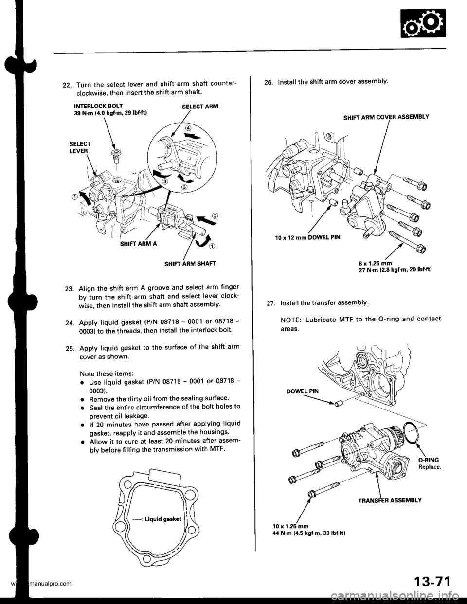
22. Turn the select lever and shift arm shaft counter-
clockwise, then insert the shift arm shaft.
INTERLOCK EOLT39 N.m (4.0 kqt ft, 29 lbf ft)SELECT ARM
SHIFT ARM A
Align the shift arm A groove and select arm finger
by turn the shift arm shaft and select lever clock-
wise. then installthe shift arm shaft assembly.
Apply liquid gasket (P/N 08718 - 0001 or 08718 -
OO03) to the threads, then install the interlock bolt'
Apply liquid gasket to the surface of the shift arm
cover as snown.
Note these items:
. Use liquid gasket (P/N 08718 - 0001 or 08718 -
0003).
. Remove the dirtv oilfrom the sealing surface.
. Seal the entire circumference of the bolt holes to
prevent oil leakage.
. lf 20 minutes have passed after applying liquid
gasket. reapply it and assemble the housings.
a Allow it to cure at least 20 minutes after assem-
bly betore filling the transmission with MTF.
23.
-->.-
(
SHIFT ARM SHAFT
SHIFT ARM COVER ASSEMBLY
10 x 12 mft DOWEL PIN
t1
26. Install the shift arm cover assembly.
I x 1.25 mm27 N m 12.8 kgt m,20 lbf'ft)
Install the transfer assemblY.
NOTE: Lubricate MTF to the O-ring and contact
areas.
10 x 1.25 mm44 N.m 14.5 kgf.m, 33 lbl.ftl
13-71
www.emanualpro.com