main HONDA CR-V 1998 RD1-RD3 / 1.G Repair Manual
[x] Cancel search | Manufacturer: HONDA, Model Year: 1998, Model line: CR-V, Model: HONDA CR-V 1998 RD1-RD3 / 1.GPages: 1395, PDF Size: 35.62 MB
Page 363 of 1395
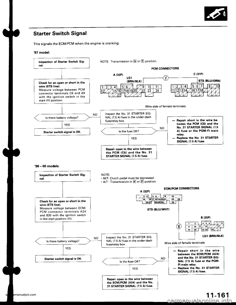
Starter Switch Signal
This signals the ECM/PCM when the engine is cranking.
'97 model:
A {32P}
'98 - 00 models:
Transmission in E or E position.
LGl(BBN/BLK)
PCM CONNECTORS
Wire side of female terminals
ECM/PCM CONI{ECTORS
STS (BLU/ORNI
c t31P)
NOTE:. M/T: Clutch pedal must be depressed.. A/T: Transmission in E orE position
Check for an opan ot short in the
wire (STS linel:Measure voltage between PCM
connector terminals C6 and Ag
with the ignition switch in the
start (lll) position.
lnspect the No. 31 STARTER SIG-
NAL (7.5 A)Illse in the under'dashls there battery voltage?- Reoair short in the wire be-
tween the PCM lc6l and th.No. 31 STARTER SIGNAL 17 5A) tuse ot the PGM-FI main
reray.- Reolace the No. 31 STARTERSIGNAL t7.5 Altu.e.
Starter swiich signal i3 OK.
Repair opon in the wire betweonrh6 PCM lc6l and the No 31
STARTER SIGNAL 17.5 A)fuse.
A (32P)
Wire side oI female terminals
Check tor an open or short in thewir€ (STS line):Measure voltage between ECM/
PCM connector terminals A24
and 820 with the ignition switchin the start position (lll).
Inspect the No. 31 STARTER SIGNAL (7.5 A){use in the under-dashls there battery voltage?
- Reoair shorl in the wire
betwe€n the ECM/PCM lA2,fland the No, 31 STARTER SIG-NAL t7.5 Al tu3€ ot the PGM'Fl main rclay.- Repl.c. tho No. 31 STARTERSIGNAL 17.5 Al fu3e.
Starter switch 3ignal is OK.
Repair opon in tho wire between
the ECM/PCM {A241 and the No
31 STARTER SIGNAL (7.5 A) tu3e
1 1-161
www.emanualpro.com
Page 380 of 1395
Fuel Supply System
System Description
The fuel supply system consists of a fuel tank, in-tank
high-pressure fuel pump. PGM-Fl main relay, fuel filter,
fuel pressure regulator, fuel injectors, and fuel delivery
and return lines. This system delivers pressure-regulat-
ed fuel to the fuel injectors and cuts the fuel delivery
when the engine is not running.
Fuel Pressure
Relieving
Before disconnecting fuel pipes or hoses, release pres-
sure from the system by loosening the 12 mm banjo
bolt on the too of the fuel filter.
Do not smoke while working on the fuel system.
Ke€p open flames or sparks away from your work
area,
Be sure to relieve fuel pressure while the ignition
switch is off.
Write down the frequencies for the radio's preset
buttons.
Disconnect the battery negative cable from the bat-
tery negative terminal.
Remove the fuel fill cap.
Use a box end wrench on the 12 mm banjo bolt at
the fuel filter while holding the fuel filter with anoth-
er wrench.
Place a rag or shop towel over the '12 mm banjo bolt.
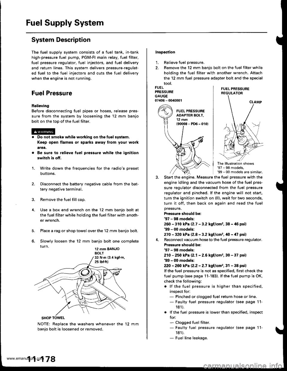
Slowly loosen the 12 mm banjo bolt one complete
rurn 12 mm BANJoBOLT
1.
SHOP TOWEL
NOTE: Replace the washers whenever the 12 mm
banio bolt is loosened or removed.
11-178
Inspection
1, Relieve fuel pressure.
2. Remove the 12 mm banjo bolt on the fuel filter while
holding the fuel filter with another wrench. Attach
the 12 mm fuel pressure adapter bolt and the special
tool.
FUEL PRESSUREREGULATON
FUELPRESSUREGAUGE07406 - 0040001
The illustration shows'97 - 98 models,'99 - 00 models are similar.
Start the engine. Measure the fuel pressure with the
engine idling and the vacuum hose of the fuel pres-
sure regulator disconnected from the fuel pressure
regulator and pinched. lf the engine will not start,
turn the ignition switch on (ll), wait for two seconds,
turn it off, then back on again and read the fuel
pressure.
Pressure should be:'97 - 98 mod€ls:
260 -31O kPa 12.7 - 3.2 kgf/cm,, 38 - 46 psil'99 - 0O models:
270 - 32O kPa Q.A - 3.2 kgf/cm'�, ifo - /U psil
Reconnect vacuum hose to the fuel pressure regulator.
Prgs3ure should be:'97 - 98 models:
210 - 25O kPa 12.1- 2.6 kgf/cm'�, 30 - 37 psi)'99 - 00 models:
22O -26iJ kPa 12.2 - 2.7 kgt/cm'�, 31 - 38 psi)
lf the fuel pressure is not as specified, first check the
fuel pump (see page 11- 183). lf the fuel pump is OK,
check the following:
. lf the fuel pressure is higher than specified,
inspect for:- Pinched or clogged fuel return hose or line.- Faulty fuel pressure regulator (see page 11-
181).
. lf the fuel pressure is lower than specified. inspect
for:- Clogged fuel filter.- Faulty fuel pressure regulator (see page 11-
1811.- Fuel line leakage.
www.emanualpro.com
Page 385 of 1395
Fuel Pump
Testing
lf you suspect a problem with the fuel pump, check that
the fuel pump actually runs; when it is oN (ll), you will
hear some noise if you hold your ear to the fuel fill port
with the fuel fill cap removed. The fuel pump should run
for two seconds when ignition switch is first turned ON (ll).
lf the fuel pump does not make noise, check it as follows:
1. Fold the left rear seat cushion forward, and remove
the base frame cover (see section 20).
2, Remove the access panel from the floor.
3. Make sure the ignition switch is OFF, then discon-
nect the fuel pumP 5P connector.
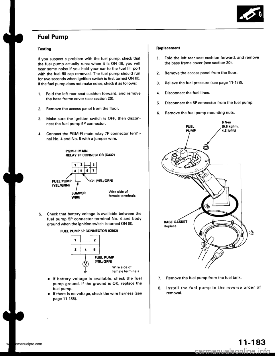
4. Connect the PGM-FI main relay 7P connector termr-
nal No. 4 and No, 5 with a jumper wire.
PGM.FI MAINRELAY 7P CONNECTOR (Cit:}2l
I'TtlJilt f -r'-r ll.l5l517l,frTt-,at\FUEL pUMp Lr- . tcl tyEL/cRNl
rYEL/cRNl IIJUMPER Wir€ side of
WIRE female terminals
5. Check that battery voltage is available between the
fuel pump 5P connector terminal No. 4 and body
ground when the ignition switch is turned ON (ll).
FUEL PUMP 5P CONNECTOR {C562}
12
3a5
lf battery voltage is available, check the fuel
pump ground. lf the ground is OK, replace the
fuel oumo.
lf there is no voltage, check the wire harness (see
page 11-188).
FUEL PUMP(YEL/GRNI
wire side offemale terminals
Raplac6mont
1. Fold the left rear seat cushion forward, and remove
the base frame cover (see section 20).
2. Remove the access panel from the floor.
3, Relieve the fuel pressure (see page 11-178).
4. Disconnect the fuel lines.
5. Disconnect the 5P connector from the fuel pump.
6. Remove the fuel pump mounting nuts.
7. Remove the fuel pump from the fuel tank.
Install the fuel pump in the reverse order of
removal.
8.
11-183
www.emanualpro.com
Page 389 of 1395
PGM-FI Main Relay
Description
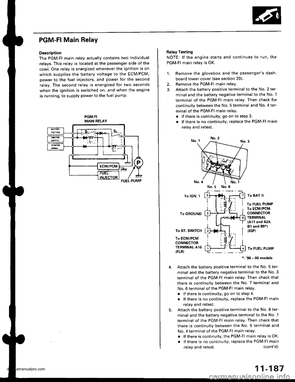
The PGM-Fl main relav actuallv contains two individual
relays. This relay is located at the passenger side of the
cowl. One relay is energized whenever the ignition is on
which supplies the battery voltage to the ECM/PCM,
power to the fuel injectors, and power for the second
relay. The second relay is energized for two seconds
when the ignition is switched on, and when the engine
is running, to supply power to the fuel pump
PGM.FIMAIN RELAY
Belay Testing
NOTE: lf the engine starts and continues to run, the
PGM-FI main relay is OK.
1. Remove the glovebox and the passenger's dash-
board lower cover (see section 20).
2. Remove the PGM-FI main relay
3. Aftach the battery positive terminal to the No. 2 ter-
minal and the battery negative terminal to the No. 1
terminal of the PGM-Fl main relay. Then check for
continuity between the No. 5 terminal and No. 4 ter-
minal of the PGM-FI main relay
. lfthere is continuity, go on to step 3.
. lf there is nocontinuity, replacethe PGM-Fl main
relav and retest.
No.2
To lGN. 1
To GROUND
To ST. SWITCH
To ECM/PCMCONNECTORTERMINAL A16(FLR)
To BAT O
To FUEL PUMPTo ECM/PCMCONNECTORTERMINAL(411 and A24,Bl .nd Bgal(IGP)
To FUEL PUMP
98 - 00 models
Attach the batterv Dositive terminal to the No. 5 ter-
minal and the battery negative terminal to the No. 3
termjnal of the PGM-Fl main relay. Then check that
there is continuity between the No. 7 terminal and
No. 6 terminal of the PGM-FI main relay.
. lf there is continuity, go on to step 4.
. lf there is nocontinuity, replacethe PGM-Fl main
relay and retest.
Attach the batterv oositive terminal to the No.6 ter-
minal and the battery negative terminal to the No. 1
terminal of the PGM-Fl main relay. Then check that
there is continuitv between the No. 5 terminal and
No. 4 terminal of the PGM-Fl main relay.
. lf there is continuity, the PGM-Fl main relay is OK.
. lf there is nocontinuity, replacethe PGM-FI main
5.
(cont'd)
11-147
No.5 No.5
relay and retest.
www.emanualpro.com
Page 390 of 1395
![HONDA CR-V 1998 RD1-RD3 / 1.G Repair Manual
Fuel Supply System
PGM-FI Main Relay (contdl
Troubleshooting
lc(}21PGM.FI MAIN RELAY 7P CONNECTOR
GND
trTr]--Flq
FI,TilI A
Y
Wire side ot female terminals
- Engine will not start.- InsDection ol PG HONDA CR-V 1998 RD1-RD3 / 1.G Repair Manual
Fuel Supply System
PGM-FI Main Relay (contdl
Troubleshooting
lc(}21PGM.FI MAIN RELAY 7P CONNECTOR
GND
trTr]--Flq
FI,TilI A
Y
Wire side ot female terminals
- Engine will not start.- InsDection ol PG](/img/13/5778/w960_5778-389.png)
Fuel Supply System
PGM-FI Main Relay (cont'dl
Troubleshooting
lc(}21PGM.FI MAIN RELAY 7P CONNECTOR
GND
trTr]--Flq
FI,Til'I A
Y
Wire side ot female terminals
- Engine will not start.- InsDection ol PGM-FI mainrelay and relay harness,
Check fo. an open in the wireIGND linol:1. Turn the ignition switch OFF.2. Disconnect the PGM Fl mainrelay 7P connector.3. Check for continuity betweenthe PGM'FI main relay 7P con-nector terminal No. 3 and bodyground.
Repair opcn in th€ wire betweenthe PGM-FI main relav and G101.
Check tor an open or short in thewiro (BAT line):Measure voltage between thePGM'FI main relay 7P connectorterminal No. 7 and body ground.- Repai. open or short in lhewir6 belween the PGM-FImain relay and the Fl E/M (15Al fu3e.- Replace th6 FIE/M (15 Altus6in th€ under-hood fuse/.6lay
ls there baftery voltage?
Check lor an open or short in thewire (lGl line):L Turn the ignition switch ON (ll).2. Measure the voltage betweenthe PGM-FI main relay 7P connectorterminal No. 5 and bodyground.- Repair open or shorl in thewire between the FGM-FI mainrelay and the No. 13 FUELPUMP 115 A) tuse.- Replaco the No. 13 RJEL PUMP115 A) luse in the und6.-d$hfuso/ relav box.Check for an open or short in thewire {STS line):1. Turn the ignition switch to theSTART (lll) position.NOTE:. M/T: Clutch pedal must bedepressed.. A/T: Transmission in E orElposition.2. Measure the voltage betweenthe PGM-Fl main retay 7Pconnector terminal No. 2 andbody ground.- Repair open or short in thewire betwe€n the PIGM-FI m.inrclay and th€ No. 31 STARTERSlGllAL 17.5 A) tuse.- Repl.ce the No. 31 STARTERSIGNAL 17.5 Al tuse in theunder-dash tuse/relay box.('97 model: To page 11-189)('98 00models:To page 1l 190)
1 1-188
www.emanualpro.com
Page 391 of 1395
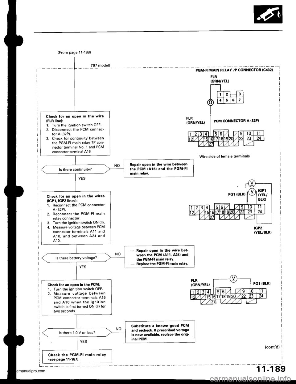
lFrom page 11 188)
Ch6ck lor an open in the wir€
{FLR line):1. Turn the ignition switch OFF.
2. Disconnect the PCM connec-
tor A (32P).
3. Check for continuity between
the PGM-FI main relay 7P con-
nector terminal No. 1 and PCM
connector terminal A16.
Repair open in the wire be{weonthe PCM lAl6l and the PGM-FImain relay.
Check for an open in the wir€s
{lGP1, lGP2lin€s):'1. Reconnect the PCM connectorA (32P).
2. Reconnect the PGM'Fl main
relay connector.3. Turn the ignition switch ON (lli.
4. Measure voltage between PCM
connector terminals A11 and
A10, and between A24 andA10.
- Repair open in the wir€ bet'
ween th€ PCM {A11, A2ia} end
the PGM-FI main relay.- Reolsce the PGM-FI main rolaY.
ls there battery voltage?
Check tor an open in the PCM:
1. Turn the ignition switch OFF.2, Measu re voltage betweenPCM connector terminals A16
and A10 when the ignition
switch is first turned ON {ll) for
Substitute a known-good PCM
and recheck. lf ptesctibed volttgeis now available, roplaco tho orig'in.lPCM.
ls there '1.0 V or less?
Check the PGM-Fl m.in.elaV(see page 11-187).
('97 model)
IGRN/YELI
-t
PGM.FI MAIN RELAY 7P CONNECTOR (C432I
FLR
Wire side of lemale terminals
IGP2(YEL/BLK)
(cont'd)
_l
1 1-1 89
www.emanualpro.com
Page 392 of 1395
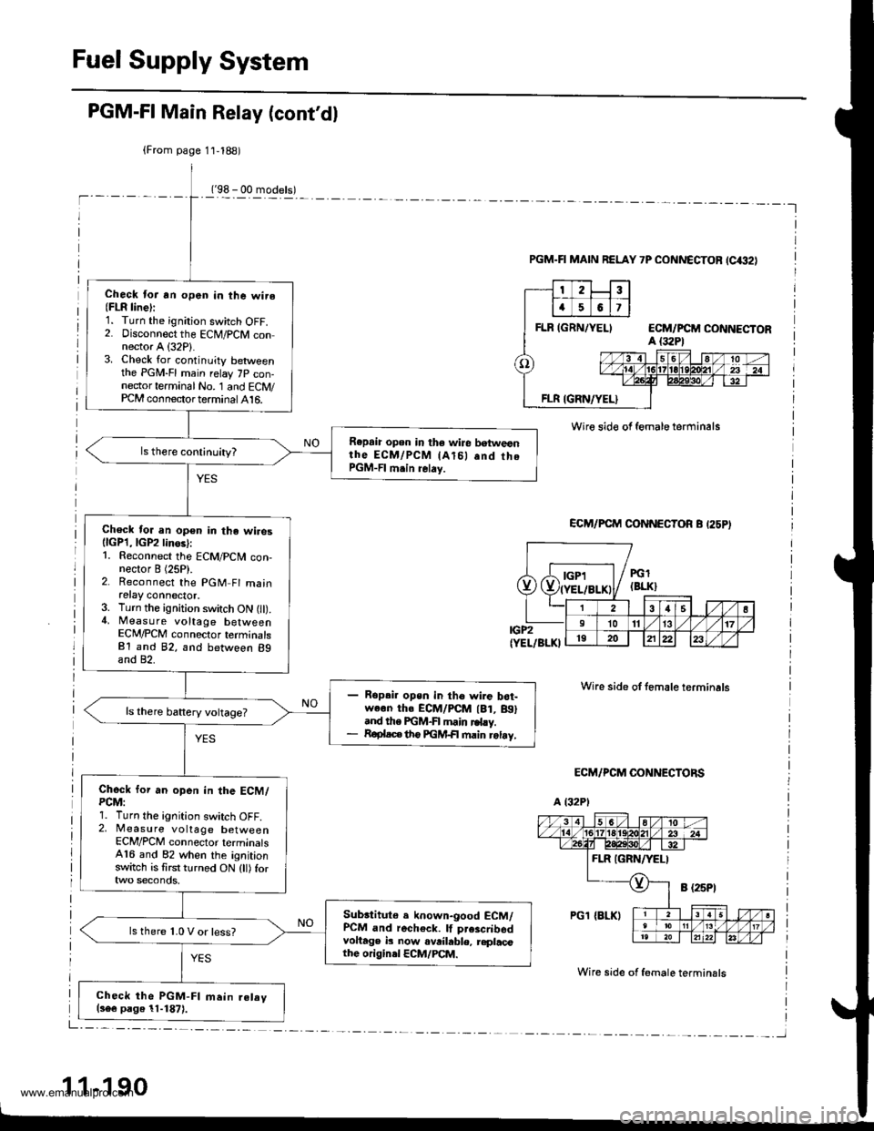
Fuel Supply System
PGM-FI Main Relay (cont'dl
('98 - 00 models)-l
(From page 11,188)
Check lor an open in the wire(FLR line):1. Turn the ignition switch OFF.2. Disconnect the ECM/PCM connector A (32P1.3. Check for continuity betweenthe PGM-FI main relay 7P con-nector terminal No. '1 and ECM/PCM connector terminal 416.
Repaia open in the wire betweenthe EcM/PcM lAl5l .nd thePGM-FI m.in relay.
Check for an open in the wiresllcPl,lGP2linos):1. Reconnect the ECM/PCN4 con-nector I (25P).2. Reconnect the PGM Fl mainretay connector.3. Turn the ignition switch ON l).4, Measure voltage betweenECM/PCM connector terminalsB1 and 82, and between 89and 82.
Ropai. open in tho wire b6t-we€n th. ECM/PCM lBt, Btl.nd the FGM-FI main rd.y.R€plac€ th6 FGM+| main retay,
Chock for an open in the ECM/PCM:1. Turn the ignition switch OFF.2, Measure voltage betweenECM/PCM connector terminals416 and 82 when the ignitionswitch is first turned ON (tl) for
Subrtitute e known-good ECM/PCM and recheck. lf prescribsdvoltage b now ovrihble, replacothe originel ECM/PCM.
ls there 1.0 V or less?
Check the PGM-FI main.elav(s6e page 11-1871.
PGM.FI MAIN RELAY 7P CONNECTOF (C€2)
Wire sid€ of female terminals
ECM/PCM CONNECTOR B I25PI
IGP2(YEL/BLKI
ECM/PCM CONNECTORS
a t32Pl
Wire side of female terminals
Wire side of f€male terminsls
1 1-190
Dde"Jt;;liL-F-T--
PGl(BLK}
38s l1011131719202122
www.emanualpro.com
Page 395 of 1395
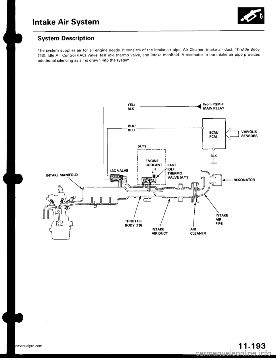
Intake Air System
System Description
The system supplies air for all engine needs. lt consists of the intake air pipe, Air Cleaner, intake air duct, Throttle Body
(TB), ldle Air Control (lAC) Valve, fast idle thermo valve, and intake manifold. A resonator in the intake air pipe provides
additional silencing as air is drawn into the system.
INTAKE MANIFOLD
YEL| - - Fiom PGM'FI
BLK T MAIN RELAY
IDLETHERMO
lJ- _iuo'u'j"'
INTAKEAIR DUCT
vaRtousSENSORS
FESONATON
THROTTLEBODY (TB)
1 1-193
www.emanualpro.com
Page 439 of 1395
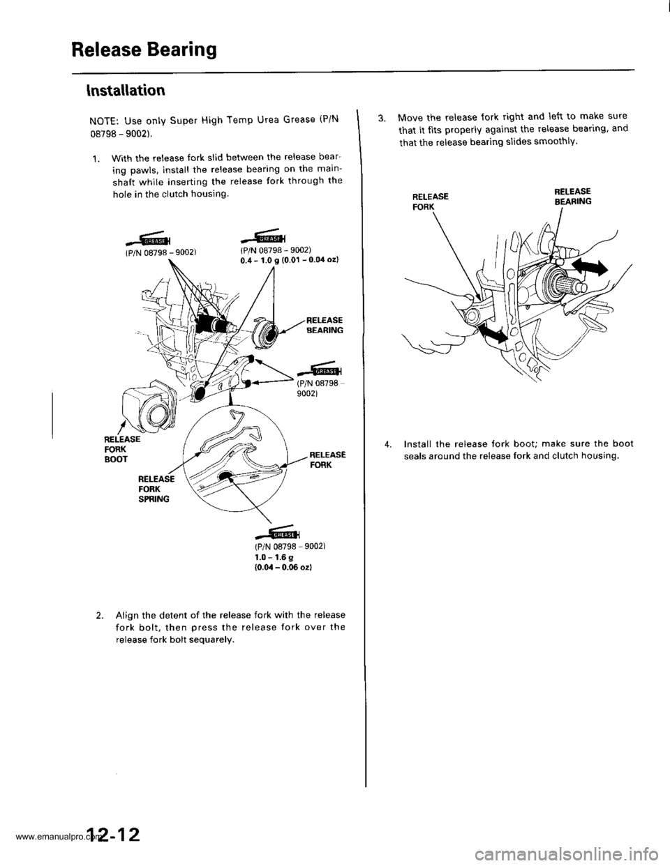
Release Bearing
lnstallation
NOTE: Use only Super High Temp Urea Grease (P/N
08798 - 9002).
1. With the release fork slid bet\iveen the release bear-
ing pawls. install the release bearing on the main-
shaft while inserting the release tork through the
hole in the clutch housing.
lPlN 08798 - 9002)0.,1- 1.0 I (0.01 - 0 04 ozl
(P/N 087989002)
(P/N 08798 9002)
1.0 - 1.6 g
{0.0,1 - 0,06 ozl
-6.l(P/N 08798 -
r iz]))
| (,4\1t1t
/\[wRELEASEFORKBOOT
Align the detent of the release fork with the release
fork bolt, then press the release fork over the
release fork bolt sequarelv.
12-12
3. Move the release lork right and left to make sure
that it tits properly against the release bear'rng. and
that the release bearing slides smoothlY.
Install the release tork boot; make sure the boot
seals around the release fork and clutch housing.
4.
www.emanualpro.com
Page 440 of 1395
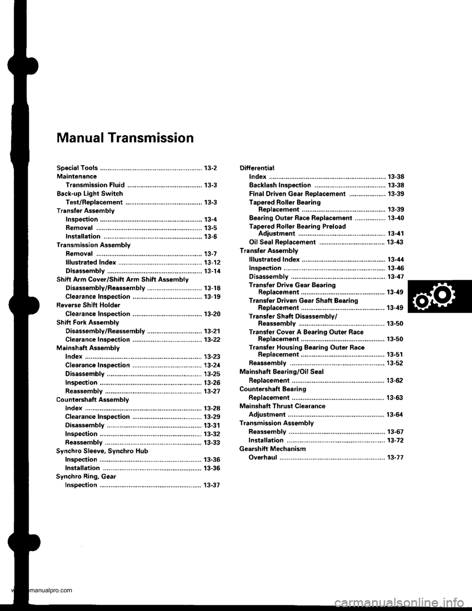
Manual Transmission
Diff€rential
lndex ...................... ......... 13-38
Backlash Inspestion ..,....,.,.....................,......, 13-38
Final Driven Gear Replacement .................... 13-39
Tapered Roller BearingReplacement ............. 13-39
Bearing Outer Race Replacement ......,.,........ 13-i10
Tapered Roller Bearing PreloadAdiustment ............... 13-il1
Oil Seal Reolacement .................................... 13-/l:}
Transfer Assembly
lllustrated Index ............. 13-il4
Inspection ..,....,.,......,...... 13-46
Disassembly ................... 13-47
Transfer Drive Gear BearingReplacement ...,..................,....................... 13-ilg
Transfer Driven Gear Shaft BearingReplacement .............................................. 13-ilg
Transfer Shaft Disassembly/Reassembly .............. 13-50
Transler Cover A Bearing Outer RaceRep1acement.........,.,.,..........,....,...,.........,., 13-50
Transter Housing Bearing Outer RaceReD1acement.............................................. 13-51
Reassembly ..-............,... 13-52
Mainshaft Bearing/Oil Seal
Beplacement .................. 13-62
Countershaft Bearing
Replacement .,,.,.,., ..,...... 13-63
Mainshaft Thrust Clearance
Adiustment .................... 13-6,1
Transmission Assembly
Reassembly .,.,.,.,..,.,....,., 13-67
fnstaffation .,.,.............,... 13-72
Gearshift Mechanism
Overhaul ................ .........13-17
www.emanualpro.com