main HONDA CR-V 1998 RD1-RD3 / 1.G Repair Manual
[x] Cancel search | Manufacturer: HONDA, Model Year: 1998, Model line: CR-V, Model: HONDA CR-V 1998 RD1-RD3 / 1.GPages: 1395, PDF Size: 35.62 MB
Page 441 of 1395
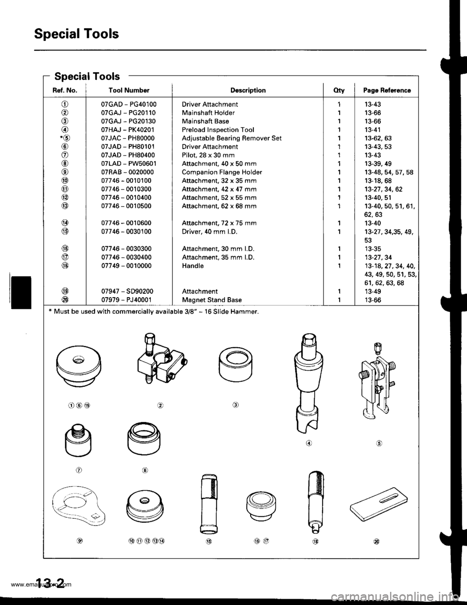
Special Tools
ll
Ref. No. I Tool NumberDsscriptionOty I Page Roterence
o
o,6)
@-o
\9'
a
@6r
@
o
@
@
@
@
@
@
@
@
@
07GAD - PG40100
07GAJ - PG20110
07GAJ - PG20130
07HAJ - PK40201
07JAC - PH80000
07JAD - PH80101
07JAD - PH80400
07LAD - PW50601
07RAB - 0020000
07746 - 0010100
07746 - 0010300
07746 - 0010400
07746 - 0010500
07746 - 0010600
07746 - 0030100
07746 - 0030300
07746 - 0030400
07749 - 0010000
07947 - SD90200
07979 - PJ40001
Driver Attachment
Mainshaft Holder
Mainshaft Base
Preload Inspection Tool
Adjustable Bearing Remover Set
Driver Attachment
Pilot, 28 x 30 mm
Attachment, 40 x 50 mm
Companion Flange Holder
Attachment,32 x 35 mm
Attachment, 42 x 47 mm
Attachment, 52 x 55 mm
Attachment, 62 x 68 mm
Attachment, 72 x 75 mm
Driver, 40 mm l.D.
Attachment. 30 mm l.D.
Attachment, 35 mm l.D.
Handle
Attachment
Magnet Stand Base
1
1
1'l
1
1
1
1
1
1'I
1
1
1
1
13-43
13-66
13-66
13-41
13-62. 63
13-43, 53
13-43
13-39, 49
13-48,54,57,58
13-18, 68
13-27,34, 62
13-40. 51't3-40, 50. 51, 61,
oz, oJ
13-40
13-27 ,34,35, 49,
tJ-5C
13-27,34
13-14,27.34, 40,
43, 49, 50, 51, 53,
61,62,63,68'13-49
13-66
* Must be used with commercially available 3/8" - 16 Slide Hammer.
o@(9ta\
oG)
,d,(oo@(9(}@o@
.A IAa 5-z
Special Tools
www.emanualpro.com
Page 442 of 1395
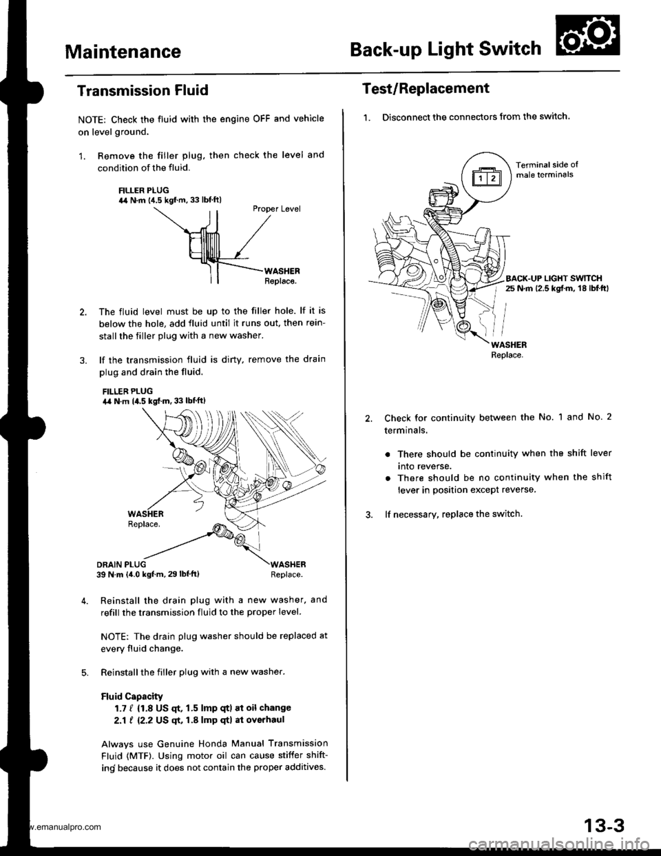
MaintenanceBack-up Light Switch
Transmission Fluid
NOTE: Check the fluid with the engine OFF and vehicle
on level ground.
1. Remove the filler plug. then check the level and
condition of the fluid.
FILLER PLUG44 N.m {4.5 kgf.m. 33 lbf ftl
ll
Ptopet Level
\--ril /
HllllllTl /
Hllllrlll /_rf-F{--rno."."
ll| | Replaco.
The fluid level must be up to the filler hole. lf it is
below the hole, add fluid until it runs out. then rein-
stall the tiller plug with a new washer.
lf the transmission fluid is diny, remove the drain
plug and drain the fluid.
FILLEB PLUGa,a N.m 14.5 kgf..n. 33 lbt'ftl
DRAIN PLUG39 N m (4.0 kgf.m, 29 lbf'ft)WASHERReplace.
Reinstall the drain plug with a new washer. and
refill the transmission fluid to the proper level.
NOTE: The drain plug washer should be replaced at
every fluid change.
Reinstall the filler plug with a new washer.
Fluid Capacity
1.7 / {1.8 US qt, 1.5 lmp qtl at oil change
2.1 ! 12.2 US qt, 1.A lmp qtl at overhaul
Alwavs use Genuine Honda Manual Transmission
Fluid (MTF). Using motor oil can cause stiffer shift-
ind because it does not contain the proper additives.
Test/Replacement
1. Disconnect the connectors from the switch.
Terminal side oImale lerminals
BACK.UP LIGHT SWTTCHr 25 N.m 12.5 kgt m, 18 lbf.ftl
WASHERReplace.
Check for continuity between the No. 1 and No. 2
terminals.
. There should be continuity when the shift lever
tnto reverse.
. There should be no continuity when the shift
lever in position except reverse,
lf necessary, replace the switch.
13-3
www.emanualpro.com
Page 450 of 1395
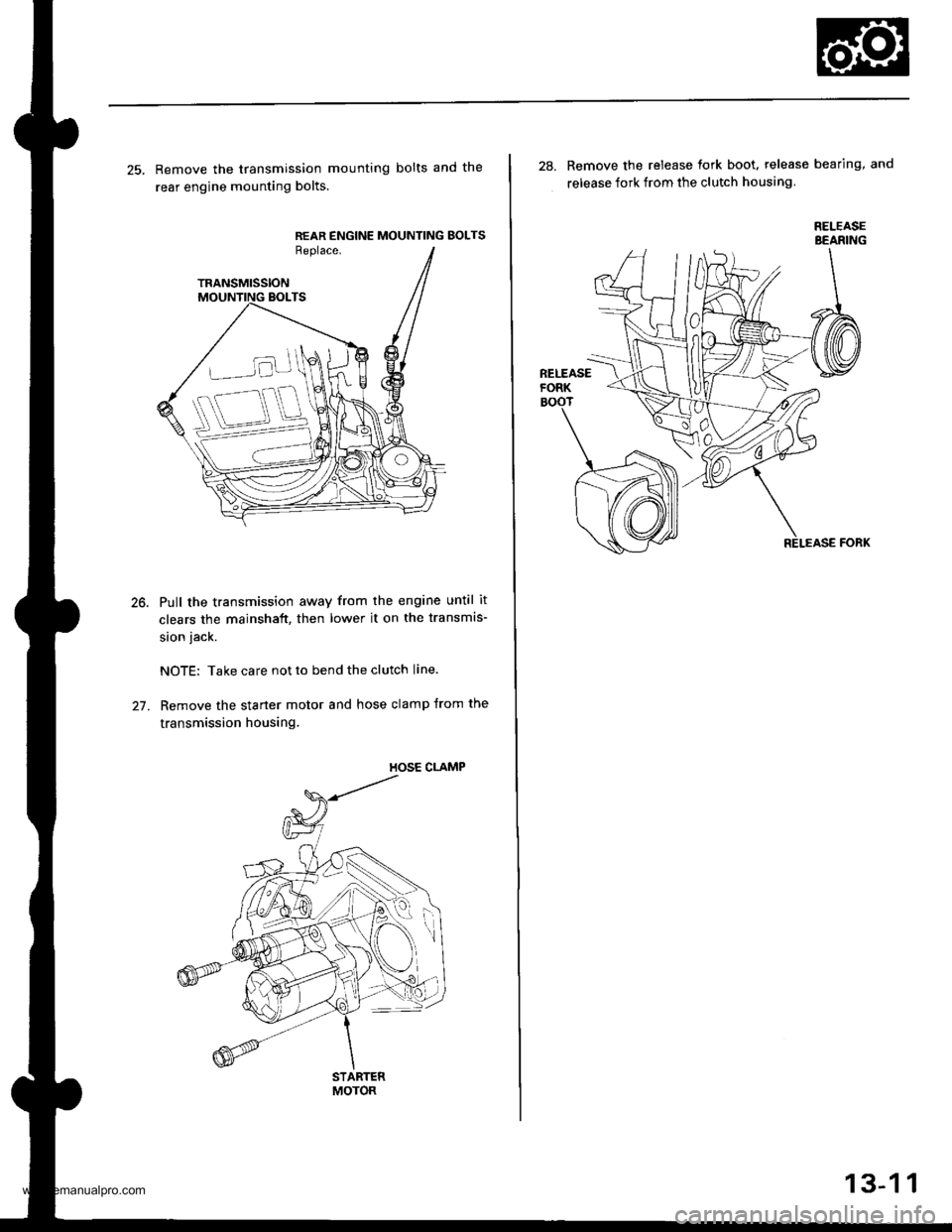
25. Remove the transmission mounting bolts and the
rear engine mounting bolts.
REAR ENGINE MOUNTING BOLTSReplace.
TRANSMISSION
Pull the transmission away from the engine until it
clears the mainshaft, then lower it on the transmis-
sion jack.
NOTE: Take care not to bend the clutch line.
Remove the starter motor and hose clamp from the
transmission housing.
STARTERMOTOR
28. Remove the release tork boot. release bearing, and
release fork from the clutch housing
RELEASEBEANING
13-1 1
www.emanualpro.com
Page 451 of 1395
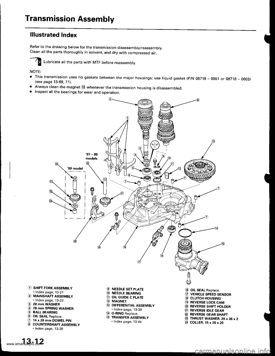
Transmission Assembly
lllustrated Index
Refer to the drawing below for the transmission disassembly/reassembly.Clean all the pans thoroughly in solvent, and drv with comoressed air.
I LuUri""r" utt the parts with MTF before reassembly.
NOTE:
t This transmission uses no gaskets between the major housings; use liquid gasket (p/N 0g718 - 0001 or oE7l8 - 0003)(see page 13-69, 71).. Always clean the magnet @ whenever the transmissjon housing is disassembled.. Inspect all the bearings for wear and operation.
C) sHrFr FoRK ASSEMBLY.Index page, l3-21(a MAINSHAFT ASSEMBLY.Index page, 13-23(9 28 mm WASHER€) 28 mm SPRTNG WASHERO BALL BEARINGa6) OIL SEAL ReDlace.(D 14 x 20 mm DOWEL ptN
G) couNTERSHAFT ASSEMBLY.lndex page, 13-28
NEEDLE SET PLATENEEDLE BEARINGOIL GUIOE C PLATEMAGNETDIFFERENTIAL ASSEMBLY.lndex page, 13-38O-nlNG Beplace.TRANSFER ASSEMBLY.Index page, '13,44
OIL SEAL Replace.VEHICLE SPEED SENSORCLUTCH HOUSINGREVERSE LOCK CAMREVEESE SHIFT HOLDERREVERSE IDLE GEARREVERSE GEAR SHAFTTHRUST WASHER,20 x 36 x 2COLLER, 15 x 20 x 20
aol
@o@@
(D
i9
@@@(9
@@@e3@
13-12
www.emanualpro.com
Page 456 of 1395
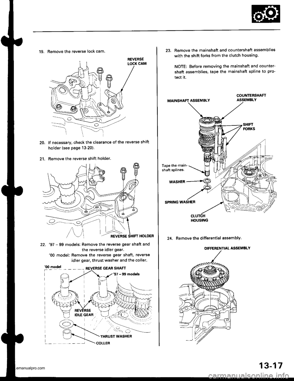
20.
2't.
19. Remove the reverse lock cam.
lf necessary, check the clearance of the reverse shift
holder (see page 13-20).
Remove the reverse shift holder.
HOLOER
22. '97 - 99 models: Remove the reverse gear shaft and
the reverse idler gear.'00 model: Remove the reverse gear shaft, reverse
idler gear, thrust washer and the coller.
13-17
23. Remove the mainshaft and countershaft assemblies
with the shift forks from the clutch housing.
NOTE; Before removing the mainshaft and counter-
shaft assemblies, tape the mainshaft spline to pro-
tect it.
ASSEMBLY
Tape the main'
shaft splines.
WASHER
SPRING WASHER
24. Remove the differential asssmbly.
COUNTEBSHAFT
HOUSING
www.emanualpro.com
Page 462 of 1395
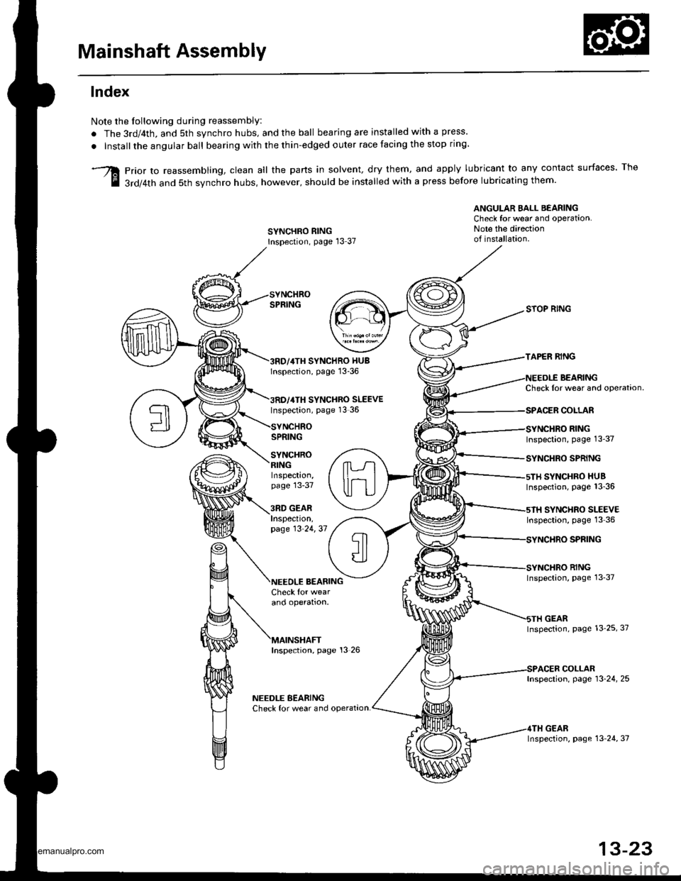
Mainshaft Assembly
lndex
Note the Iollowing during reassembly:
. The 3rd/4th, and 5th synchro hubs, and the ball bearing are installed with a press.
. Installthe angular ball bearing with the thin-edged outer race facing the stop ring
prior to reassembling, clean all the parts in solvent, dry them, and apply lubricant to any contact surfaces. The
3rd/4th and 5th svnchro hubs, however, should be installed with a press before lubricating them'
ANGULAR EALL BEARINGCheck for wear and operation.Note the directionof installation.SYNCHRO RINGInspection, page l3 37
SYNCHRO HUBlnspection, page 13-36
SYNCHRO SLEEVEInspection, page 13 36
SPRING
SYNCHRO
SYOP RING
TAPER RING
BEARINGCheck Ior wear and operataon.
COLLAR
RINGInspection, page 13-37
SYNCHRO SPRING
SYNCHRO HUBInspection, page 13_36
SYNCHRO SLEEVEInspection, page 13 36
SPFING
RINGInspection, page 13_37
GEARInspection, page 13_25, 37
COLLARInspection, page 13-24, 25
GEARInspection, page 13 24, 37
Inspection,page 13-37
3RD GEARInspeclton,page 13 24,37
BEARINGCheck for wearano operalton.
Inspection, page 13 26
NEEDLE BEARINGCheck for wear and operat,on.
13-23
www.emanualpro.com
Page 463 of 1395
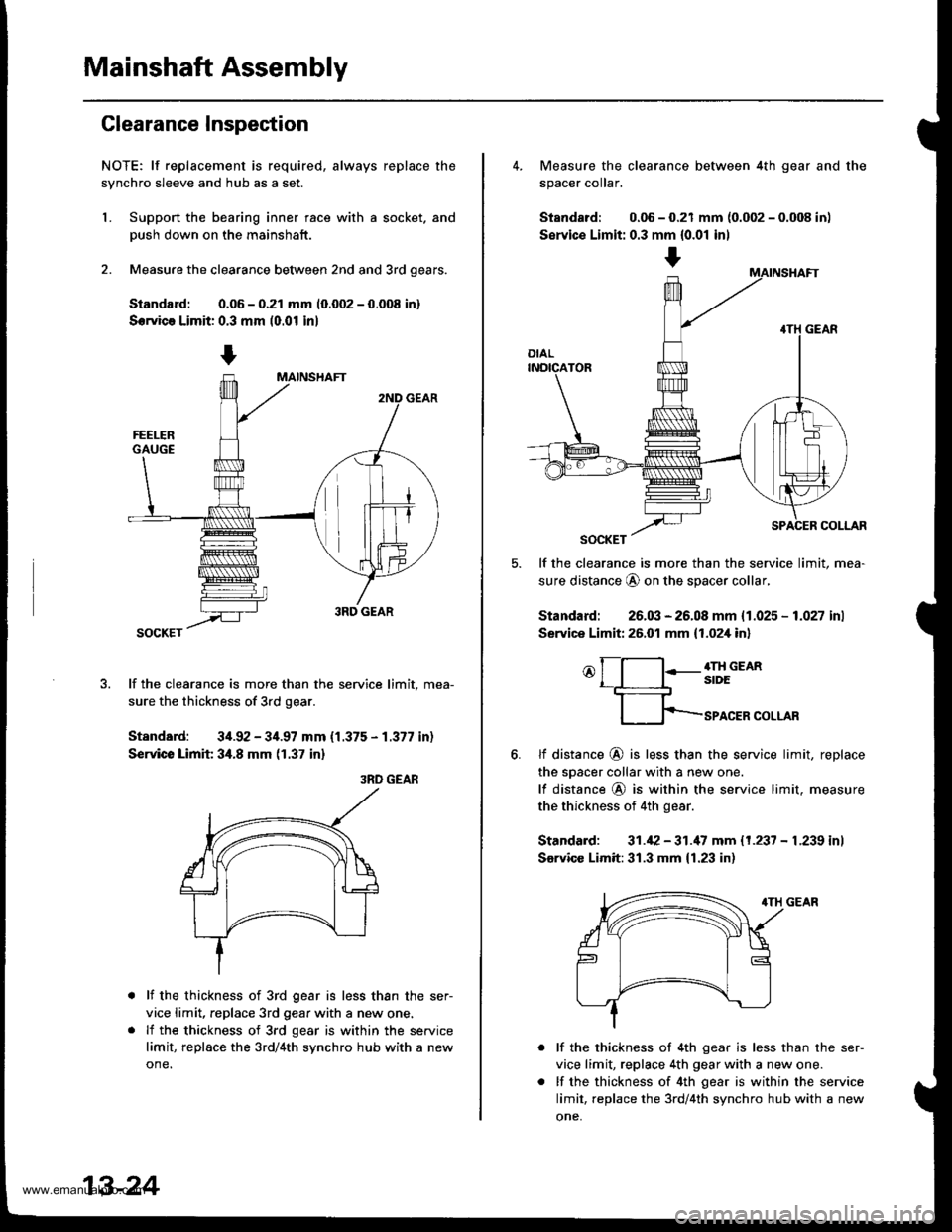
Mainshaft Assembly
Clearance Inspection
NOTE; lf replacement is required, always replace the
synchro sleeve and hub as a set.
L Support the bearing inner race with a socket. and
Dush down on the mainshaft.
2. Measure the clearance between 2nd and 3rd oears.
Siandard: 0.06 - 0.21 mm 10.002 - 0.008 in)
Servica Limit: 0.3 mm (0.01 in)
lf the clearance is more than the service limit, mea-
sure the thickness of 3rd gear.
Standard: 34.92 - 34.97 mm {1.375 - 1.377 in)
Service Limit 34.8 mm (1.37 in)
3RD GEAR
lf the thickness of 3rd gear is less than the ser-
vice limit, replace 3rd gear with a new one.
lf the thickness of 3rd gear is within the service
limit, replace the 3rd/4th synchro hub with a new
one.
13-24
+
4. Measure the clearance between 4th gear and the
spacer coIar,
Standard: 0.06 - 0.21 mm {0.002 - 0.008 in)
Servic€ Limit: 0.3 mm {0.01 inl
lf the clearance is more than the service limit, mea-
sure distance @ on the spacer collar,
Standard: 26.03 - 26.08 mm {1.025 - 1.027 inl
Service Limit: 26.01 mm {1.02,[ in]
o[-l:-g;;em
fp-rro.ERcoLLAR
6.tf distance @ is less than the service limit, replace
the sDacer collar with a new one.
lf distance @ is within the service limit. measure
the thickness of 4th gear.
Standard: 31.42 - 31.'17 mm 11.237 - L239 inl
Sarvicc Limit:31.3 mm {1.23 in)
lf the thickness of 4th gear is less than the ser-
vice limit, replace 4th gear with a new one.
lf the thickness of 4th gear is within the service
limit, replace the 3rd/4th synchro hub with a new
one,
www.emanualpro.com
Page 464 of 1395
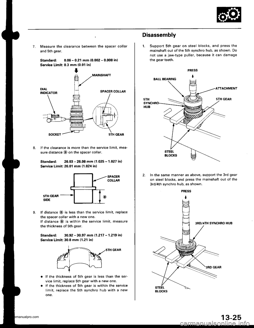
7. Measure the clearance between the spacer collar
and 5th gear.
Standard: 0.06 - 0.21 mm {0.002 - 0.008 in)
Service Limit: 0.3 mm {0.01 in)
MAINSHAFT
SPACER COLLAR
8.
SOCKET5TH GEAR
lf the clearance is more than the service limit, mea-
sure distance @ on the spacer collar
Standard: 26.03 - 26.08 mm 11.025 - 1.027 in)
S€rvico Limit: 26.01 mm (1.024 in)
9.
SPACERCOLLAR
5TH GEARSIDE
lf distance @ is less than the service limit, replace
the spacer collar with a new one.
lf distance @ is within the service limit, measure
the thickness of sth gear.
Standard: 30.92 - 30.97 mm (1.217 - 1.219 in)
Service Limit: 30.8 mm (1.21 in)
r-- ,,srH GEAR
gt Fq
I .J'-----!--\--J-l
lf the thickness of 5th gear is less than the ser-
vice limit, replace 5th gear with a new one.
li the thickness of sth gear is within the service
limit, replace the sth synchro hub with a new
one.
Disassembly
1. Support 5th gear on steel blocks, and press the
mainshaft out of the 5th synchro hub, as shown. Do
not use a jaw-type puller, because it can damage
the gear teeth.
PRESS
I
ACHMENT
In the same manner as above, support the 3rd gear
on steel blocks. and press the mainshaft out of the
3rd/4th svnchro hub, as shown.
PRESS
I
BLOCKS
www.emanualpro.com
Page 465 of 1395
Mainshaft Assembly
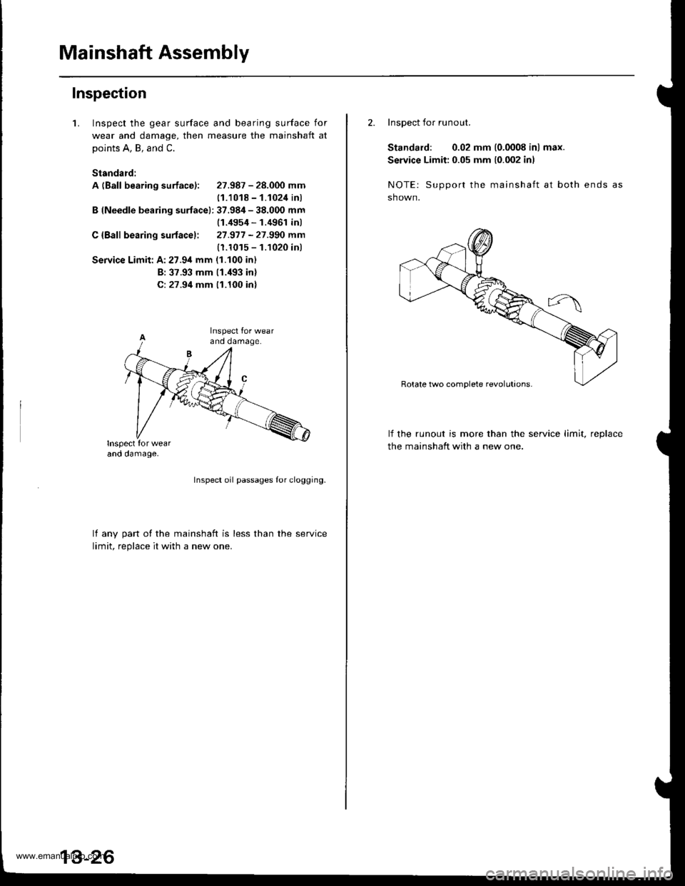
Inspection
1.Inspect the gear surface and bearing surface for
wear and damage, then measure the mainshaft at
points A, B, and C.
Standard:
A (Ball bearing surface): 27.987 - 28.000 mm
11.1018 - 1.1024 inl
B (Needle bearing surfacel: 37.984 - 38.000 mm(1.4954 - 1.4961 inl
C {Bafl bearing surfacel: 27.977 -27.990 mm
(1.1015 - 1.1020 inl
Service Limit: A:27.94 mm (1.100 in)
B: 37.93 mm (1.'193 inl
C: 27.94 mm 11.100 inl
Inspect oil passages Ior clogging.
lf anv oart of the mainshaft is less than the service
limit. reolace it with a new one.
2. Inspect for runout.
Standard: 0.02 mm (0.0008 in) max.
Service Limit: 0.05 mm 10.002 inl
NOTE: Support the mainshaft at both ends
sh own.
lf the runout is more than the service limit, reDlace
the mainshaft with a new one.
www.emanualpro.com
Page 480 of 1395
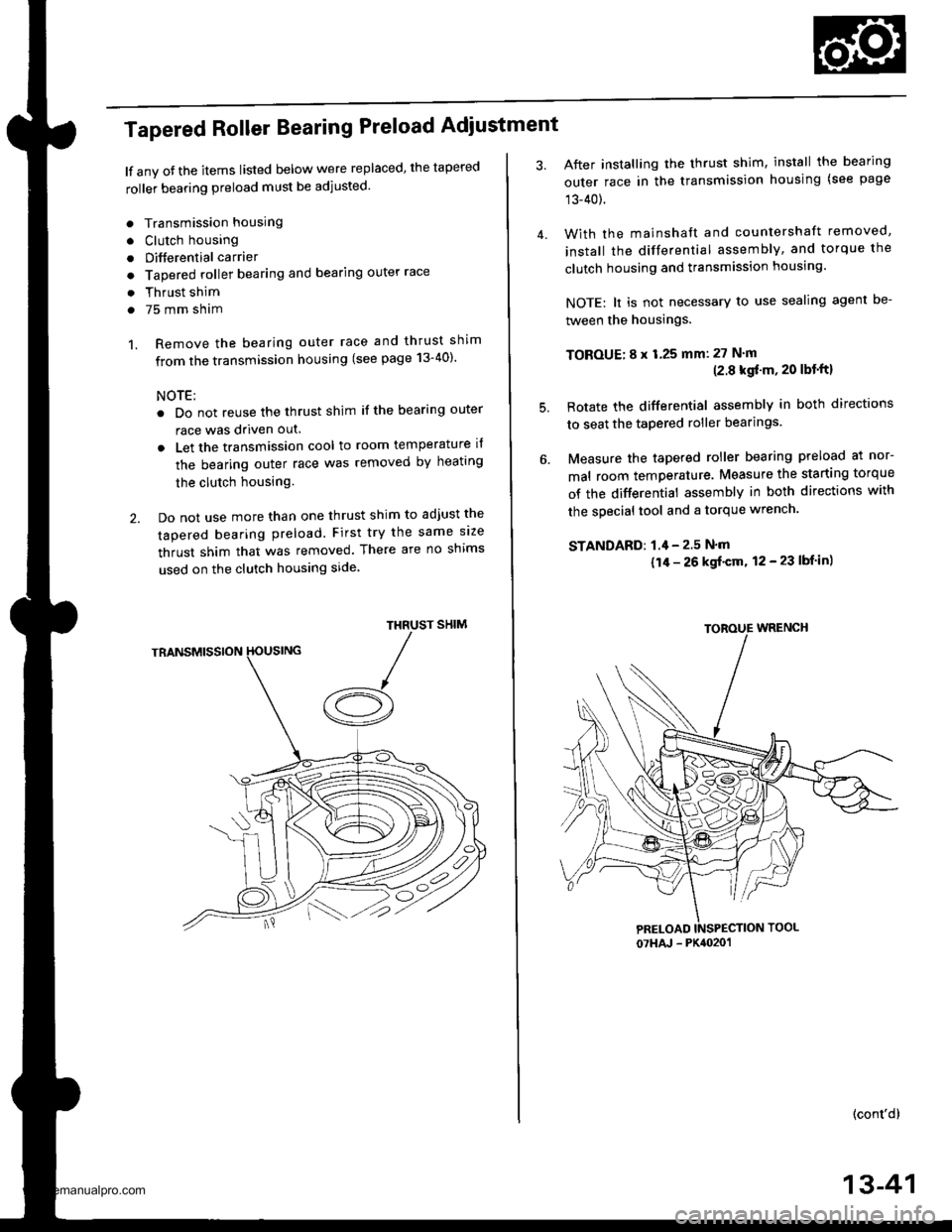
Tapered Roller Bearing Preload Adiustment
lf any oJ the items listed below were replaced, the tapered
roller bearing preload must be adjusted.
. Transmission housing
. Clutch housing
. Differential carrier
o Tapered roller bearing and bearing outer race
. Thrust shim
. 75 mm sham
1. Remove the bearing outer race and thrust shim
from the transmission housing (see page 13-40)'
NOTE:
. Do not reuse the thrust shim if the bearing outer
race was driven out.
. Let the transmission cool to room temperature il
the bearing outer race was removed by heating
the clutch housing.
2. Do not use more than one thrust shim to adjust the
tapered bearing preload. First try the same size
thrust shim that was removed. There are no shims
used on the clutch housing side
SHIMTHRUST
/A
After installing the thrust shim, install the bearing
outer race in the transmission housing (see page
13-40).
With the mainshaft and countershaft removed,
install the differential assembly, and torque the
clutch housing and transmission housing.
NOTE: lt is not necessary to use sealing agent be-
tween the housings.
TOBOUE; 8 x 1.25 mm: 27 N'm(2.8 kgf'm, 20 lbt'ftl
Rotate the differential assembly in both directions
to seat the tapered roller bearings.
Measure the tapered roller bearing preload at nor-
mal room temperature. Measure the starting torque
of the differential assembly in both directions with
the special tool and a torque wrench.
STANDAFD: 1.4 - 2.5 N'm
{1/r - 26 kgf'cm, 12 - 23 lbf in)
(cont'd)
4.
5.
07HAJ - PK4020'�1
13-41
www.emanualpro.com