Electric HONDA CR-V 1998 RD1-RD3 / 1.G Repair Manual
[x] Cancel search | Manufacturer: HONDA, Model Year: 1998, Model line: CR-V, Model: HONDA CR-V 1998 RD1-RD3 / 1.GPages: 1395, PDF Size: 35.62 MB
Page 620 of 1395
Electrical Troubleshooting ('98 - 00 Model)
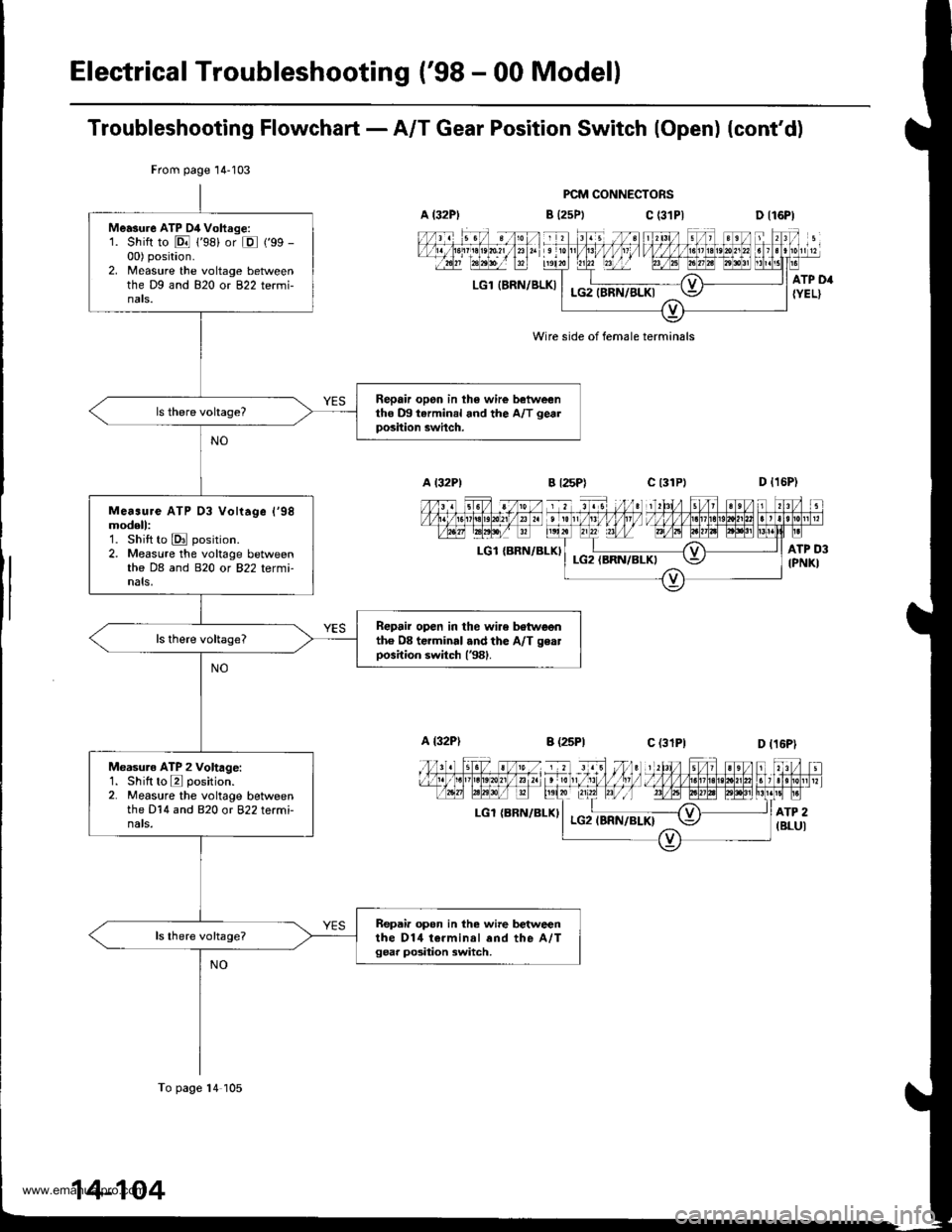
Troubleshooting Flowchart - A/T Gear Position Switch (Open) (cont'd)
PCM CONNECTORS
B {25Ptc (31P|
LGl IERN/BLKI
Wire side of female terminals
LGl {BRN/BLKI
LGl {BRN/ELXI
From page 14-103
Me.sure ATP D4 Vohrge:1. Shift to E 1'98) or E ('99 -
00) position.2. Measure the voltage betweenthe Dg and 820 or 822 termi-nats.
Repair opon in th6 wire betweentho m tarminal and the A/T gealposition swhch.
Me..ure ATP 03 Vohage l'98modell:1. Shift to E position.2. Measure the voltage betweenthe DB and 820 or 822 tetmi-nals,
Repair open in the wire botwoonth6 08 terminal .nd the A/T geatposition switch (381.
Measuro ATP 2 Voltage:1. Shilt to E position.2. Measure the voltage betweenthe D14 and 820 or 822 terminats.
Repair opon in the wire betweenthe D14 t€.minal end the A,/Tgear po3ition switch,
To page 14 105
www.emanualpro.com
Page 622 of 1395
Electrical Troubleshooting ('98 - 00 Models)
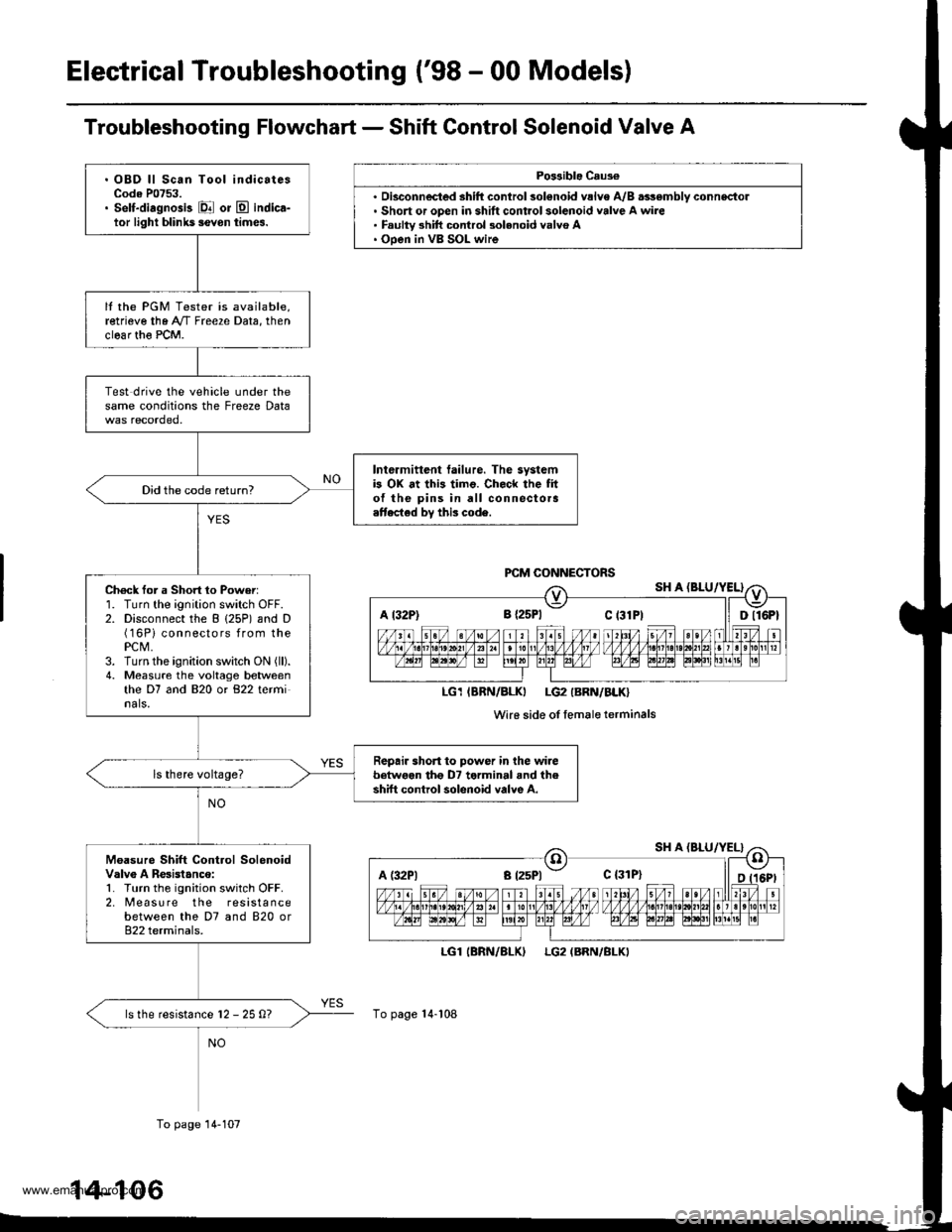
Troubleshooting Flowchart - Shift Control Solenoid Valve A
Po$ible Caus€
'. Short or open in shift control solenoid valve A wire. Faulty 3hift control 3olenoid valvo A. Ooen in VB SOL wire
LGl
To page 14-108
(BRN/BLKILG2 (BRN/BLKI
A t32P) 8 {2sPl Ct3lPt ll Dll6Pt
LG1IBRN/BLKI LG2IBRN/BLK}
Wi16 side of femaleterminals
A (:l2Pl a t25Pl - c {31P}
. OBD ll Scan Tool indicatesCode P0753.. Self-diagnosis El or E indica-tor light blihk5 ievon times.
It the PGM Tester is available,retrieve the A"/T Freeze Data, thenclear th€ PCM.
Test drive the vehicle under thesame conditions the Freeze Data
Intermittent tailure. The systemb OX at this timo. Check the fito{ the pins in all connectora.ttected by this code.
Did the code return?
Ch6ck for a Short 1o Power:1. Turn the ignition switch OFF.2. Disconnect the B (25P) and D(16Pi connectors from thePCM,3. Turn the ignition switch ON (ll).
4. Measure the voltage betweenthe D7 and 820 or 822 terminals.
Repair short to power in the wirebetwoen tho D7 terminal and theshift control solenoid valve A.
Moasure Shift Control SolenoidValv6 A Resistanco:1. Turn the ignition switch OFF.2. [reasu re the resistancebetween the D7 and 820 or822 terminals.
ls the resistance l2 - 25 0?
To page 14-107
14-106
www.emanualpro.com
Page 624 of 1395
Electrical Troubleshooting ('98 - 00 Models)
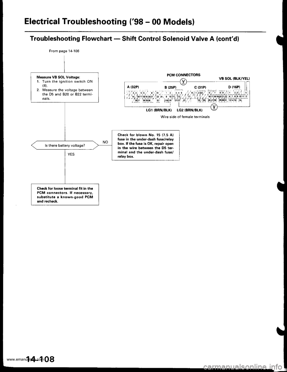
Troubleshooting Flowchart - Shift Control Solenoid Valve A (cont'd)
From page 14-106
Wire side of female terminals
Moasure VB SOL Voftago:1. Turn the ignition switch ONflr).2. Measure the voltage betweenthe D5 and 820 or 822 termi-nals,
Check lor blown No. 15 (7.5 Alfuse in the under-dash fuse/relaybox. lf the tuse is OK, repair openin the wi.e between the D5 ter-minal and the under-dash fuse/relay box.
ls there battery vohage?
Check for loose terminalfit in thePCM connectors. lf necessary,subltitute a known-good PCMand recheck.
VB SOL IBLK/YEL)
14-108
www.emanualpro.com
Page 626 of 1395
Electrical Troubleshooting ('98 - 00 Models)
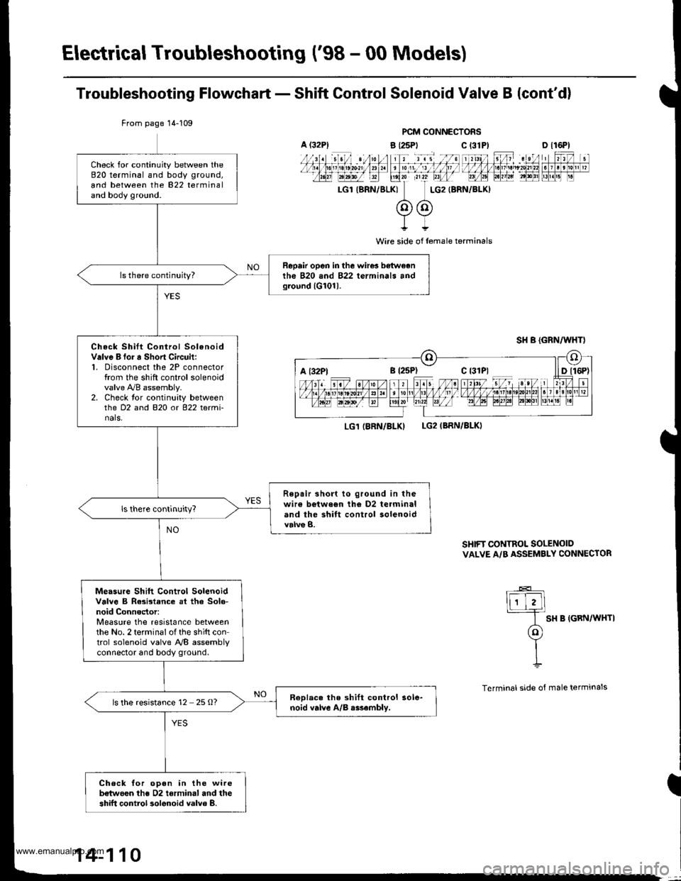
Troubleshooting Flowchart - Shift Control Solenoid Valve B {cont'd)
PCM CONNECTORS
a {25P) C t31
I
Wire side of l6male terminals
LG1 IBRN/BLKILG2IBRN/BLKI
SHIFT CONTROL SOLENOIDVALVE A/B ASSEMBLY CONNECTOR
lF-E]
I SH B IGRN/WHTI
(ol
YII
Terminal side of male terminals
From page 14-109
Check for continuity between the820 terminal and body ground,
and between the 822 terminaland body ground.
Repair open in the wire! b€twoenth6 B20 and 822 terminals andground lG101l.
Check Shilt Control SolenoidValve B for a Sho.t Circuit:1, Disconnect the 2P connectorfrom the shift control solenoidvalve !VB assembly.2. Check tor continuity betweenthe D2 and B2O o( 822 tetmi-nals,
Repair short to ground in thewir€ b€twe6n th€ D2 terminaland the shift control solenoidvalve B.
Measu.e Shift Control SolenoidValve B Rasistance at tha Solo-noid Connector:Measure the resistance betweenthe No. 2 terminal of the shift control solenoid valve NB assemblvconnector and body ground.
ReDlac. the shift control sole-noid valve A/B r$embly.ls the resistance 12 25 O?
Check for oDen in the wireb€twoen ths D2 torminal and theshift control 3olenoid valve 8.
A (32P1c 13lPlD tl6Pl
a t32Ptc {31P1
14-110
www.emanualpro.com
Page 628 of 1395
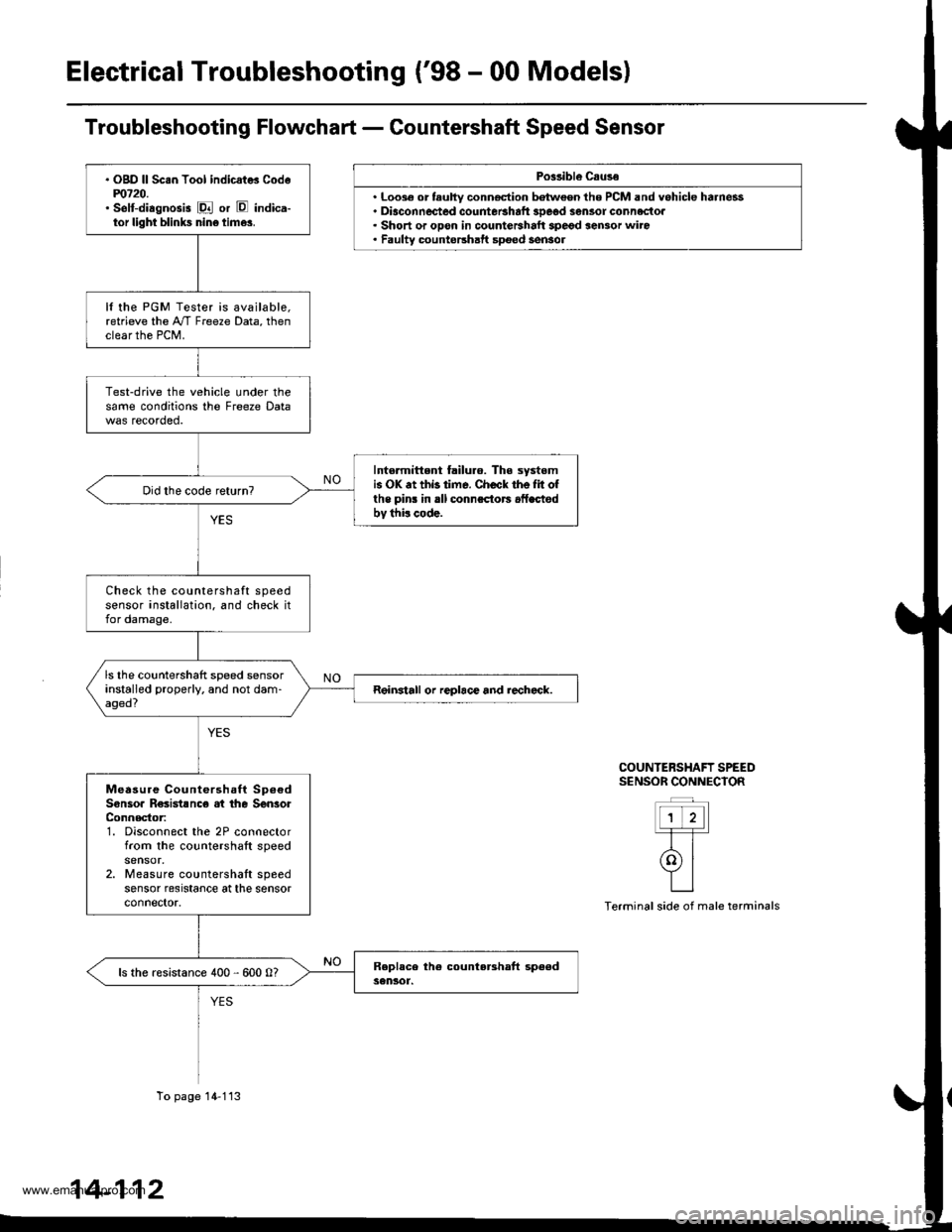
Electrical Troubleshooting ('98 - 00 Models)
Po$ibl€ Csuse
. Loo3€ or tauhy conn€ction batween the PCM and vehicle harness. Diaconnected countetshaft 3Deod sensor connectoa. Short or opon in countershalt spegd sensor wiro. Faulty countershatt spoed sensol
COUNTERSHAFT SPEEDS€NSOR CONNECIOR
ttt'l-T-T-
rolYILI
Terminal side of male terminals
. OgD ll Sc.n Tool indicat* Codem720.' selt-diagnosis E or E indica-tor light blinks nin6 time3.
It the PGM Tester is available,retrieve the A"/T Freeze Data, thenclear the PCM.
Test-drive the vehicle under thesame conditions the Freeze Data
Intormittent failuro. The systomis OK .t thb time. Check the Iit ofthe pins in rll connsctors .fLctodbv thi! code.
Check the countershaft speedsensor installation. and check itfor damage.
ls the countershaft speed sensorinstalled properly. and not dam-aged?Reinstall or replace and rechcck.
Measure Countershaft Sp6€dSonsoa R€sistsnc€ at the SenlorConnector:1. Disconnect the 2P connectorfrom the countershaft speed
2. Measure countershaft speedsensor resrstance at the sensorconnector.
ls the resistance 400 - 600 0?
To page 14-113
14-112
www.emanualpro.com
Page 630 of 1395
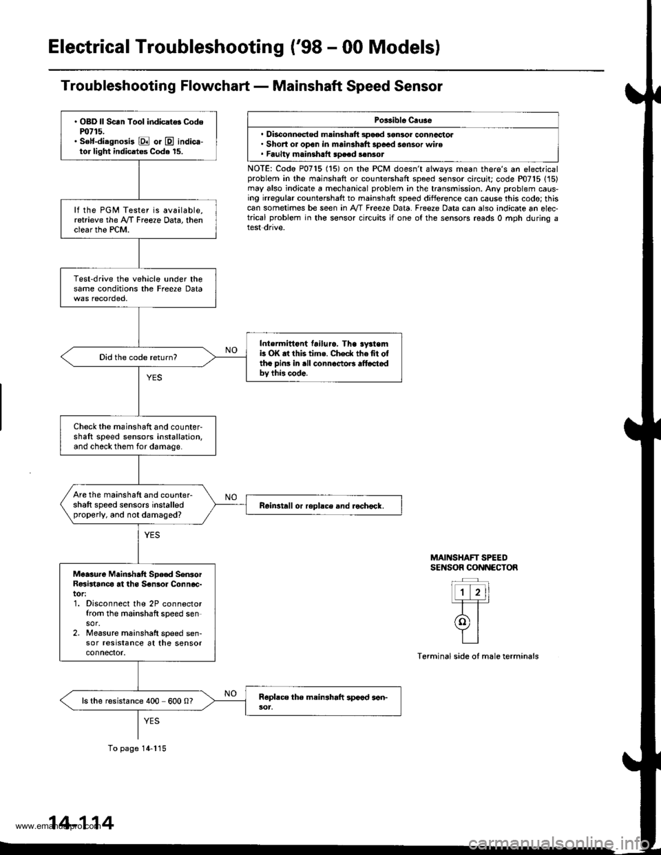
Electrical Troubleshooting ('98 - 00 Modelsl
Troubleshooting Flowchart - Mainshaft Speed Sensor
Porsible Cruse
. Disconnsct€d msinsh.ft 3pood 3gnlor conncctol. Short or open in mainshaft 3poed sensor wire. Faultv mainshrtt speed sonsot
NOTE: Codo P0715 (15) on the PCM doesn't always moan there's an electricalproblem in the mainshaft or countershaft speed sensor circuit; code P07'15 (15)may also indicate a mechanical problem in the transmission. Any problem caus-ing irregular countershaft to mainshaft spoed difference can cause this codo; thiscan sometimes be seen in A'/T Free2e Data. Freeze Data can also indicate an elec-trical problem in the sensor circuits ;f one of the sensors reads 0 mph during atest dnve.
MAINSHAFT SPEEDSENSOR CONNECTOR
Terminal side of male terminals
. OBD ll Scan Tool indicat$ Codem715.. S€lf-diagnosi3 E or @ indica-tor light indicatos Code 15.
lf the PGM Tester is available,retrieve the A/f Freeze Data, thenclear the PCM.
Test-drive the vehicle under thesame conditions the Freere Data
Intermittont tailuro. Tha sy3temb OK at this tims. Check thefit oftho pins in .ll connoctoB alt6ctedbv this code.
Did the code return?
Check the mainshaft and counter-shaft speed sensors installation,and check them for damage.
Are the mainshaft and counter-shaft speed sensors installedproperly, and not damaged?Reinstall or ropllce and rochock.
Moasure Mainshatt Spe€d SenrorR€sirtanco at ths S€nsol Connoc-tor:1. Disconnect the 2P connectorfrom the mainshaft speed sensor.2. Measure mainshatt speed sen-sor resrstance at the sensorconnefior.
ls the resistance 400 600 0?
To page 14-115
14-114
www.emanualpro.com
Page 632 of 1395
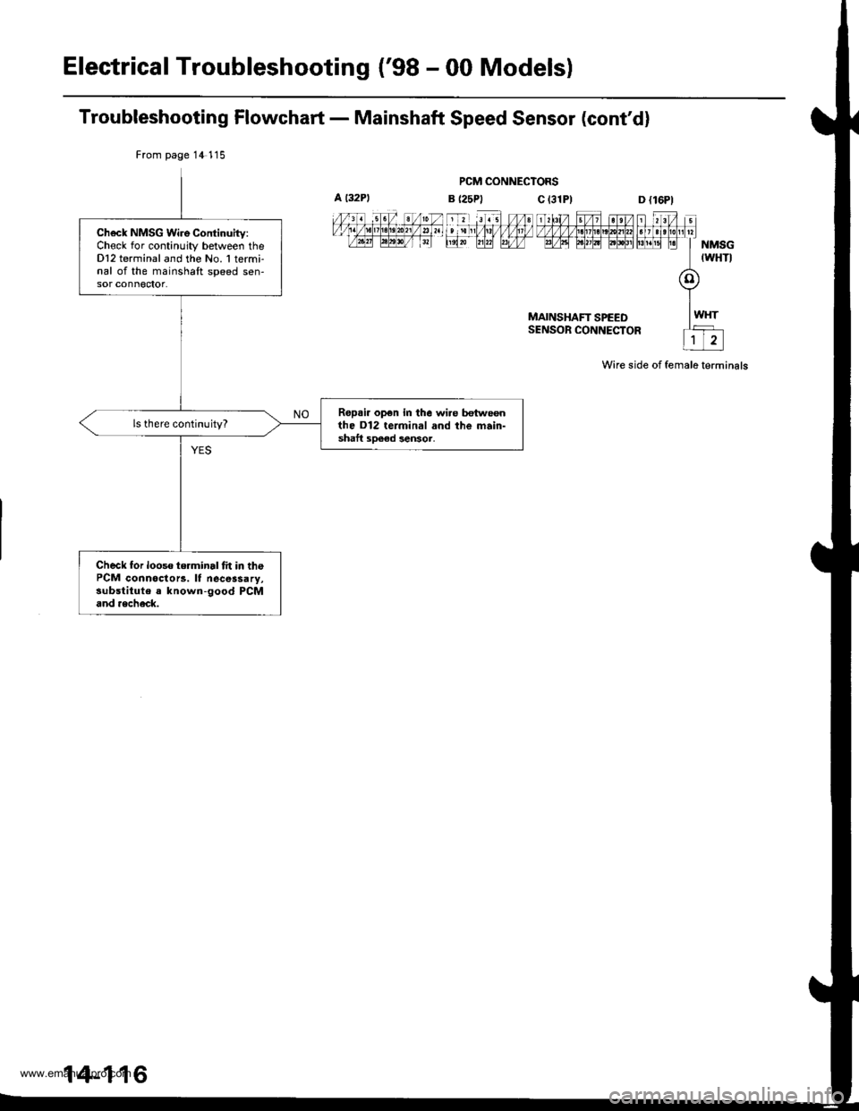
Electrical Troubleshooting ('98 - 00 Models)
Troubleshooting Flowchart - Mainshaft Speed Sensor (cont'd)
PCM CONNECTORS
MAINSHAFT SPEEDSENSOR CONNECTOR
Wire side of female terminals
From page 14 115
Ch6ck NMSG Wire Continuitv:Chock for continuity between theDl2 terminal and the No. 1 termi-nal of the mainshaft speed sen-sor conn€ctot.
Ropai. op€n in the wi.e hn eonthe D12 terminal and the main-shaft sDeed lensor,
ls there continuity?
Check for looso terminal fit in thePCM connoctorc. lf necessary,substitute a known-good PCMand aech6ck.
14-116
www.emanualpro.com
Page 634 of 1395
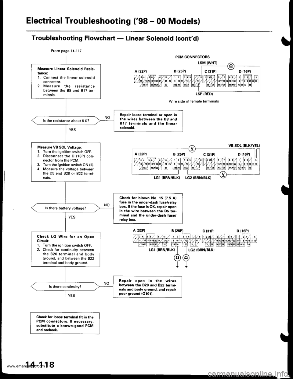
ElectricalTroubleshooting ('98 - 00 Models)
Troubleshooting Flowchaft - Linear Solenoid (cont'dl
Wire side of female terminals
LG2 {BRN/BLKI
From page 14-117
Measure Linea. Solenoid Resis-tance:1. Connect the linear solenoidconnector,2. Measure the resistancebetween the 88 and 817 termrnals,
Repair loose torminal oi open inthe wires between rhe 88 and817 terminals and the linearsolenoid.
ls the resistance about 5 O?
Measure VB SOL Voltago:1. Turn the ignition switch OFF.2. Disconnect the D 116P) con-nector trom the PCM.3. Turn the ignition switch ON (ll).4. Measure the voltage betweenthe D5 and 920 ot B22 tetmi-nals.
Check for blown No. 15 17.5 Alfuse in the under-da3h tus€/relaybox. lI the fuse is OK, rap.ir openin the wire betwe€n the D5 ter-minal and th€ under-dash tuso/relav box.
ls there baftery voltsge?
Check LG Wire for.n OpenCircuit:1. Turn the ignition switch OFF.2. Check for continuity betweenthe 820 terminal and bodyground, and between the 822terminal and body ground.
Repair op6n in the wirosbetwe€n the 820 and 822 termi-nals and body ground, and repairpoor g.ound iG101).
ls there continuity?
Chack tor loose terminel fit in thePCM connecto13. It nocosaary,substitute a known-good PCM.nd recheck,
a t32Plc t3lPl
LSP (REO)
a l32Pl
A (32P1
LGl IBRN/BLK}
B l2sP)c 13lPlD l16P)
14-118
www.emanualpro.com
Page 636 of 1395
Electrical Troubleshooting ('98 - 00 Models)
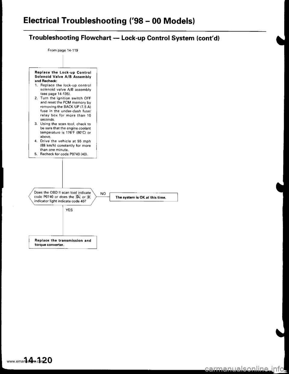
Troubleshooting Flowchart - Lock-up Control System (cont'd)
From page 14-119
Replace the Lock-up ControlSolenoid Valve A/B Assomblyand Recheck:1. Replace the lock-up controlsolenoid valve A,/B assembly(see page 14-!35).2. Turn the ignition switch OFFand reset the PCM memory byremoving the BACK UP (7.5 A)fuse in the undeFdash fuse/relay box for more than 10seconds.3. Using the scan tool, check tobe sure that the engine coolanttemperature is 176"F {80'C) orabove.4. Drive the vehicle at 55 mph(88 km/h) constantly tor morethan one minute.5. Recheck {or code P0740 (40i.
Does the OBD ll scan tool indicatecode P0740 or does the [9i] or Eindicator light indicate code 40?The system is OK at this time.
14-120
www.emanualpro.com
Page 638 of 1395
Electrical Troubleshooting {'gB - 00 Models}
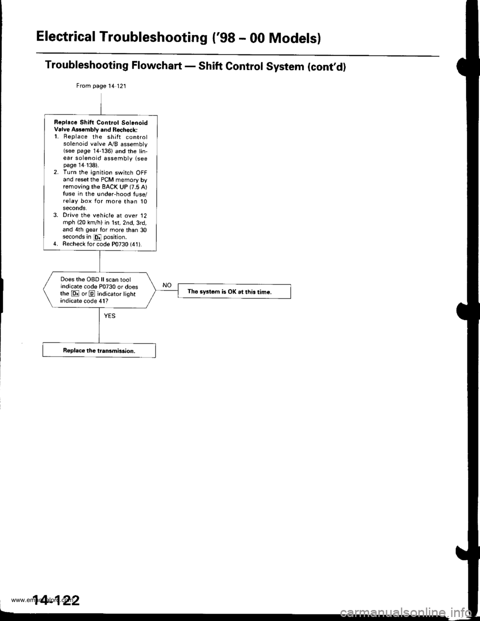
Troubleshooting Flowchart - Shift Control System (cont,d)
From page 14 121
Replace Shilt Cont.ol SolenoidValve A$ambly and Recheck:'1. Replace the shift controlsolenoid valve A/B assembly(see page 14-136) and the lin,ear solenoid assembly (seepage 14138).2. Turn the ignition switch OFFand reset the PCM memory byremoving the BACK UP (7.5 A)tuse in the !nder-hood luse/relay box for more than 10seconos.3. Drive the vehicle at over '12
mph (20 km,/ti) in lst,2nd,3rd,and 4th gear tor more than 30seconds in E position.4. Recheck for code P0730 (41).
Does the OBD ll scan toolindicate code P0730 or doesthe E orE indicator lightindicate code 41?
Tho system is OK .l this tim€.
www.emanualpro.com