PCM HONDA CR-V 1998 RD1-RD3 / 1.G Repair Manual
[x] Cancel search | Manufacturer: HONDA, Model Year: 1998, Model line: CR-V, Model: HONDA CR-V 1998 RD1-RD3 / 1.GPages: 1395, PDF Size: 35.62 MB
Page 315 of 1395
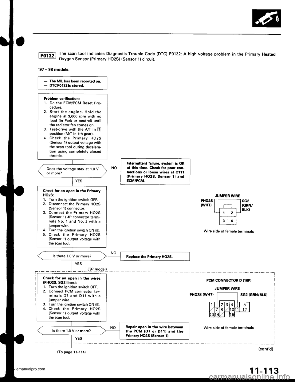
The scan tool indicates Diagnostic Trouble Code (DTC) P0132: A high voltage problem in the Primary HeatedOxygen Sensor {Primary HO2S) (Sensor 1) circuit.
'97 - 98 models:
PHO2S
IWHTIsG2IGRN/BLK}
Wire side ot female terminals
PCM CONNECTOR D {16PI
JUMPER WIRE
PHO2S IWHTISG2 IGRN/BLK}
Wire side of temale terminals
I
(cont'dl
11-113
Problem verification:1. Do the ECM/PCM Resot Pro,ceoute,2. Start the engine. Hold theengine at 3,000 rpm with noload (in Park or neutral) untilthe radiator fan comes on.3. Test-drive with the Ay'T in Eposition (M/T in 4th gear).4. Check the Primary H02S{Sensor 1}output voltage withthe scan tool during decelera-tion using completely closedthrottle.
Intormittent l.ilure, 3ystem ia OKat thb timo. Chcck fo. poor con-nections 01 looso wi.es at C111{Prim!ry HO2S, Sensor 1} andECM/PCM.
Does the voltage stay at 1.0 V
Check for an open in th6 PrimaryH()2S:1. Turn the ignition switch OFF.2. Disconnect the Primary HO2S(Sensor 1) connector-3. Connect the Primary HO25lSensor 1) 4P connector termi-nals No. 1 and No. 2 with ajumper wire.4. Turn the ignition switch ON (ll).5. Check the Primary HO2S(Sensor 1) output voltage withthe scan tool,
ls there 1.0 V or more?
Ch€ck for an opon in the wires(PHO2S, SG2linesl:1. Turn the ignition switch OFF.2. Connect PCM connector ter-minals D7 and Dl1 with a
3. Turn the ignition switch ON (ll).4. Check the Primary HO2S{Sensor 1) output voltage withthe scan tool.
Roprir opon in the wire betweontho PCM {D7 01 D11l and thePrimsry HO2S {S6nsor 1).
ls there 1.0 V or more?
{'97 model}
{To page 11-114)
www.emanualpro.com
Page 316 of 1395
PGM-FI System
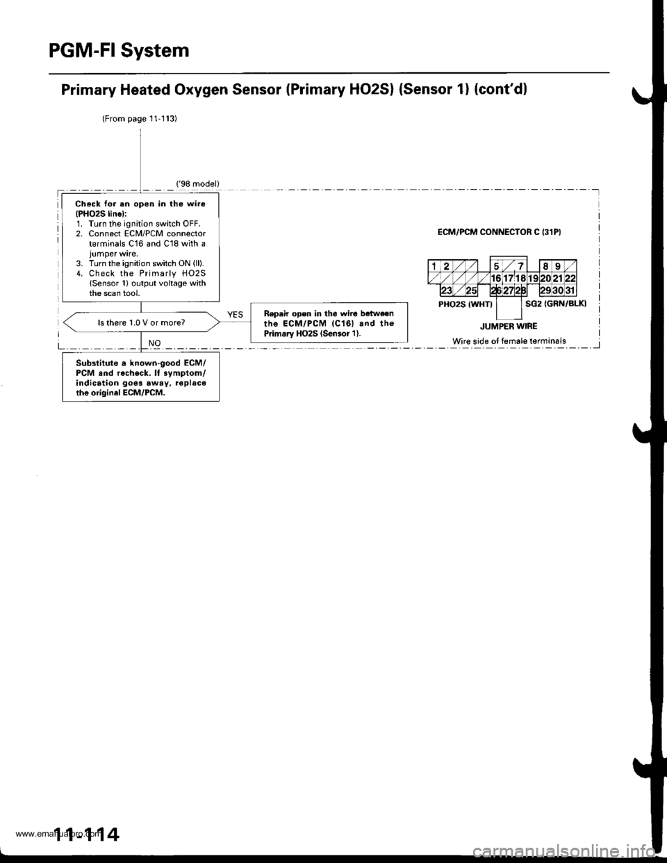
Primary Heated Oxygen Sensor lPrimary HO2S) {Sensor 1} {cont'dl
(From page'11-l13)
ECM/PCM CONNECTOR C {31PI
11-114
Ch.ck for an open in the wire(PHO2S linel:1. Turn the ignition switch OFF.2. Connect ECM/PCM connectorterminals C16 and C18 with a
3. Turn the ignition switch ON {ll).4. Check the Primarly H02S(Sensor 1) output voltage withthe scan tool.
R€p.ir open in the wire bqtw€enthe ECM/PCM (C161 and th€Primary HO2S (Sen.or'l).ls there 1,0 V or more?
Substitute a known-good ECM/PCM and rach€ck. lt 3ymptom/indication goos away, replacethe origin.l ECM/PCM.
www.emanualpro.com
Page 317 of 1395
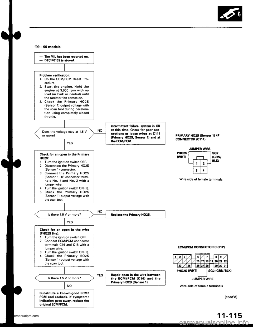
'99 - 00 modols:
Th6 Mll has b€on reDortod on.DTC ml32 is itorod.
Problem vorification:'1. Do the ECi!4/PCM Reset Procedure,Start the ongine. Hold theengine at 3,000 rpm with noload (in Park or neutral) untilthe radiator fan comes on.Check the Primary HO2SlSensor 1) output voltage withthe scan tool during decelela-tion using completely closedthroftle.
Int.rmitt .fi tailuro, syltom b OKat thit tima. Check for poor con-nactiona oi loo3a wirar !t Cltl(Primrry HO2S, S.nror 1) .nd .tth. ECM/FCM.
Doos the voitage stay at 1.5 Vor more?
Check for an opsn in the PrlmaryHO2S:1. Turn the ignition switch OFF.2. Disconnect the Primary HO2S(Sensor 1)connector.3. Connect the Primary HO2S(Sensor 1) 4P connector t6rmi-nals No. 1 and No. 2 with a
iumperwire.4. Turn the ignition switch ON (ll).
5, Check the Primsry H02S(Sensor 1) output voltage withthe scan tool,
lsthere 1.5 V or more?
Check for an op6n in th6 wiro{PHO2S line):1. Turn tho ignition switch OFF.2. Connect ECM/PCM connectorterminals C16 and C18 with a
iumper wire.3. Turn the ignition switch ON lll).4. Check the Primary HO2S(Sensor 1) output voltage withthe scan tool.
Ropair opon in thc wire bc{w.cnthe ECM/PCM {Cl6}.nd thePrimary HO2S {S€nror 1}.ls there 1.5 V or more?
Substituto a known-good ECM/PCM snd rochock. lf 3ymptom/indicetion go€a awry, roplaca thoorigin.l ECM/PCM.
PRIMARY HOzS (S6n!or 1l aPCoNNECTOR lcltl)
Pt()2sIWHTIsG2{GRN/BTJ(I
Wire side of tem6le terminsls
ECM/PCM CONNECTOR C (31P}
IGRN/BLKI
JUMPER WIRE
Wire side ol temale t6rmin6ls
(cont'd)
-1 15
2789
/1617't819120A22
23E29g)31
PHO2S {WHTIsG2
11
www.emanualpro.com
Page 318 of 1395
PGM-FI System
Primary Heated Oxygen Sensor (Primary HO2S) lSensor 1) (cont'd)
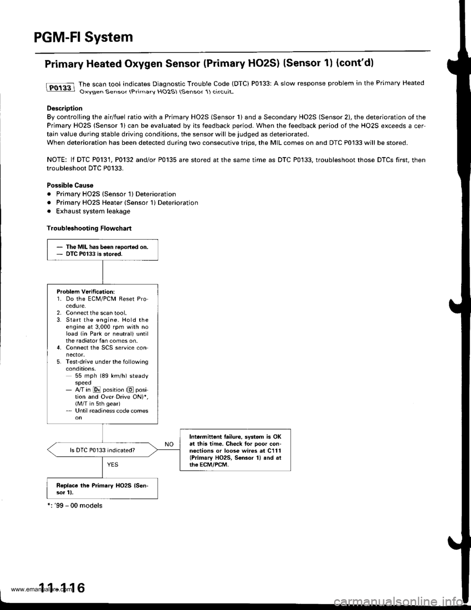
tFO133 lhe scan tool indicates Diagnostic Trouble Code (DTC) P0133: A slow response problem in the Primary Heated: Oxysen Sensor (Primarv HO2S (Sensor 1) circuit.
Description
By controlling the airlfuel ratio with a Primary HO2S (Sensor 1) and a Secondary HO2S (Sensor 2), the deterioration of the
Primary HO2S (Sensor 1) can be evaluated by its feedback period. When the feedback period of the HO2S exceeds a cer
tain value during stable driving conditions, the sensor will be judged as deteriorated.
When deterioration has been detected during two consecutive trips, the MIL comes on and DTC P0133 will be stored.
NOTE: lf DTC P0131, P0132 and/or P0135 are stored at the same time as DTC P0133. troubleshoot those DTCS first, then
troubleshoot DTC P0133.
Possible Cause
. Primary HO2S (Sensor 1) Deterioration
. Primary HO2S Heater (Sensor 1) Deterioration
. Exhaust system leakage
Troubleshooting Flowchart
- The MIL has b6€n reoorted on.- DTC P0133 is stored.
Problem Verilication:'1. Do the ECM/PCM Reset Procedure.2. Connect the scan tool.3. Start the engine. Hold theengine at 3,000 rpm with noload lin Park or neutrali untilthe radiator fan comes on.4. Connect the SCS service connector.5. Test-drive under the followingcondations,55 mph (89 km/h) steadyspeed- M in @ position (E position and Over Drive ON)*,(M/T in sth gear)- Until readiness code comes
Intermittent failure, system is OKat this time. Check tor poor con-nections or loose wires at C111(Primary HO2S, Sensor 1) and althe ECM/PCM.
Replace the Primary HO2S {Sen-sor 11.
1 1-1 16
www.emanualpro.com
Page 319 of 1395
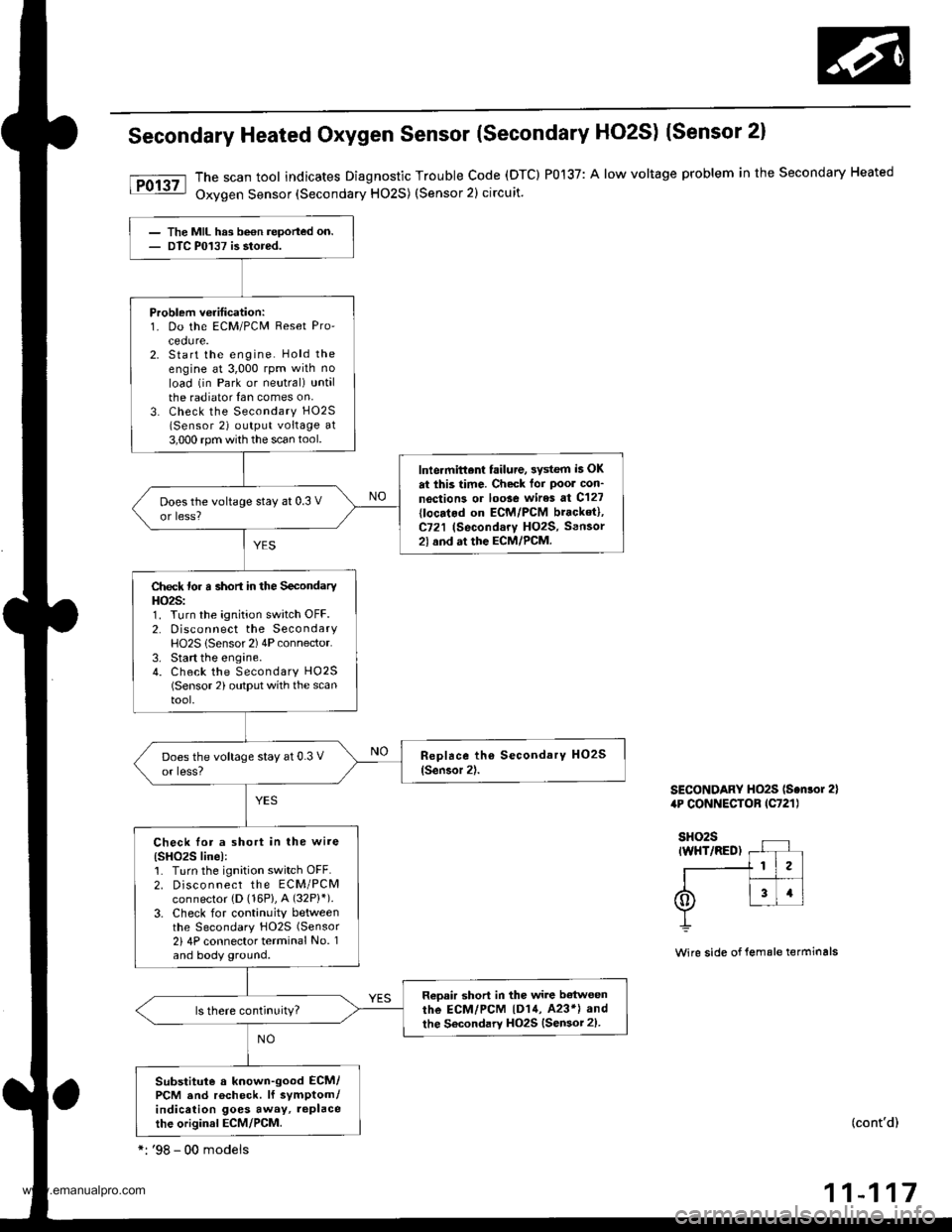
Secondary Heated Oxygen Sensor (Secondary HO2S) (Sensor 2)
The scan tool indicates Diagnostic Trouble code (DTC) P0137: A low voltage problem in the secondary Heated
Oxygen Sensor (Secondary HO2S) (Sensor 2) circuit.
SECONDARY HO2S ls.nlor 2)4P CONNECTOB lC721l
Wire side of lemale terminals
(cont'd)
11-117
The MIL hrs been reported on.DTC P0137 is stored.
Problem veritication:1. Do the ECM/PCM Reset Pro'cedure.2. Start the engine. Hold theengine at 3,000 rpm wilh no
load (in Park or neutral) untalthe radiator {an comes on,3. Check the Secondary H02S
lSensor 2) output voltage at3,000 rpm with the scan tool.
lnlermittent failure, 3ystem i5 OK
at this time. Check tor Poor con'
noction3 or loose wires at C127
{locatod on ECM/PCM bracket},C721 (Secondary HO2S, Sensor2l and at the ECM/PCM.
Does the voltage stay at 0.3 V
or less?
Check for a short in the SecondaryHO2S:1. Turn the ignition switch OFF.2. Disconnect the SecondaryHO2S lSensor 2) 4P connector.3. Start the engine.4. Check the Secondary HO25(Sensor 2) output with the scantool.
Check lor a short in the wire(SHO2S linel:1. Turn the ignition switch OFF.2. Disco n nect the ECM/PCMconnector {D (16P}, A (32P}').
3. Check for continuity betweenthe Secondary HO2S (Sensor
2i 4P connector terminal No. 1and body ground.
Reoair short in the wire b€twoen
rhe ECM/PCM |D14, 423*l and
the Secondary HO2S {Sensor 2).
Substitute a known-good ECM/PCM and rocheck. lf symptom/indication goes away, replacethe original ECM/PCM.
*: '98 - 00 modeis
www.emanualpro.com
Page 320 of 1395
PGM-FI System
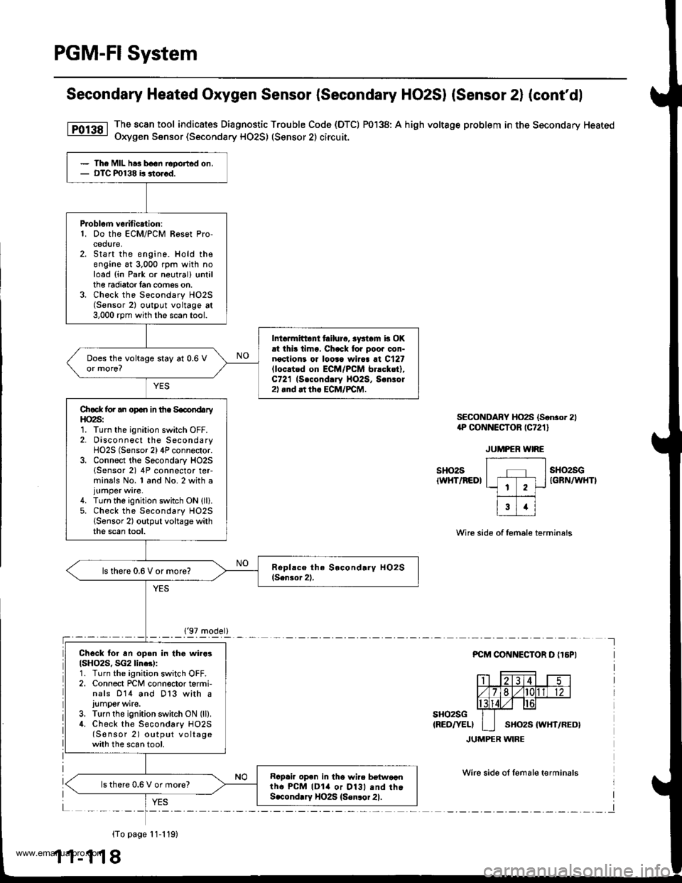
Secondary Heated Oxygen Sensor (Secondary HO2SI (Sensor 2l (cont'dl
The scan tool indicates Diagnostic Trouble Code (DTC) P0138: A high voltage problem in the Secondary Heated
Oxygen Sensor (Secondary HO2S) (Sensor 2) circuit.
SECONDABY HO2S (Sonror 2)1P CONNECTOR rC721 l
sHo2s{WHT/REDI
sH()2sGIGFN/WHTI
Wire side of female terminals
PCM COI{NECTOR D {16PI
sHo2sG(RED/YELI
JUMPER WIRE
Wirc side ol lemale terminals
{To page 11-119)
1 1-1 18
The MIL hra b€on Eported on,OTC m138 b stor.d.
PJoblcm v6dtic.tion:1. Do the ECM/PCM Resot Pro-cedure,Start the engine. Hold theengine at 3,000 rpm with noload (in Park or neutral) trntilthe radiator lan comes on.Check the Secondary HO2S(Sensor 2) outpl.rt voltage at3,000 rpm with the scan tool.
Int.rmitto tailurc, syst.m b OKrt ihi! timo. Chack fo. poo. oon-noctioni or looaa wiiaa at C127lloc.ted on EcM/PcM br.cket),C721 (Second!ry llO2S, Sonlol2).nd at th. ECM/PCM.
Does the voltage stay at 0.6 Vor more?
Chock for an opon in the SocondaryHO2S:1. Turn the ignition switch OFF.2. Disconnect the SecondaryHO2S (Sensor 2) 4P connector.3. Connect the Socondary HO2S(Sensor 2) 4P connector ter-minals No. 1 and No. 2 with a
4. Turn the ignition switch ON {ll}.5. Check the Secondary HO2S{Sensor 2) output voltage withthe scan tool.
ls there 0.6 V or more?
Ch6ck for an open in thg wiro3(SH()2S, SG2 line3l:1. Turn the ignition switch OFF.2. Connect rcM connector termi-nals 014 and D13 with a
J!mper wite.3. Turn the ignition switch ON (ll).
4. Check the S€condary HO2S(S€nsor 2) output voltagewith the scan tool.
Rapair op6n in tho wir. b€{woantho PcM lDla or Dl3l .nd thoS.condlry HO2S {Senlor 21.
lsthere 0.6 V or more?
('97 model)
www.emanualpro.com
Page 321 of 1395
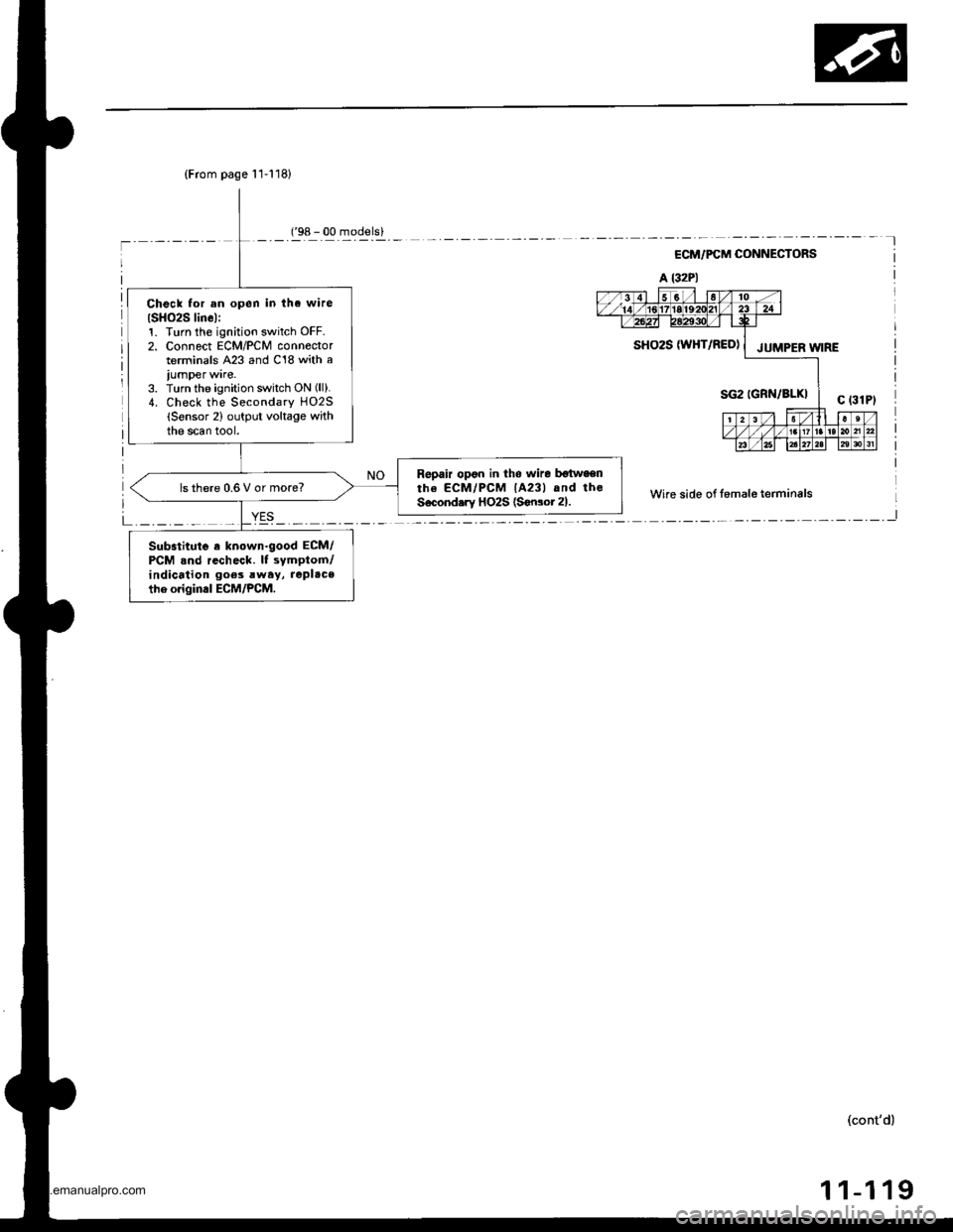
(From page 11-118)
Check for an open in tha wire
ISH()2S linel:1. Turn th€ ignition switch OFF.2. Connect ECM/PCM connectorterminals A23 and C18 with a
iumper ware.3. Turn the ignition switch ON (ll).
4. Check the Secondary HO2S(Sensor 2) output voltage withthe scan tool.
Repair opon in tho wire botwaenthe ECM/PCM lA23l and theSecond.ry HO2S (Sonsot 21.ls there 0.6 V or more?
Substitute a known.good ECM/PCM .nd recheck. It symptom/indication goes rway, replace
the origin.l ECM/PCM.
('98 - 00 models)
ECM/PCM CONNECTORS
A l32Pl
Wire side of fomale terminals
L _._._ _ _I
SHO2S W}iT/RED) | JUMpER W;RE
(cont'd)
1 1-1 19
www.emanualpro.com
Page 322 of 1395
PGM-FI System
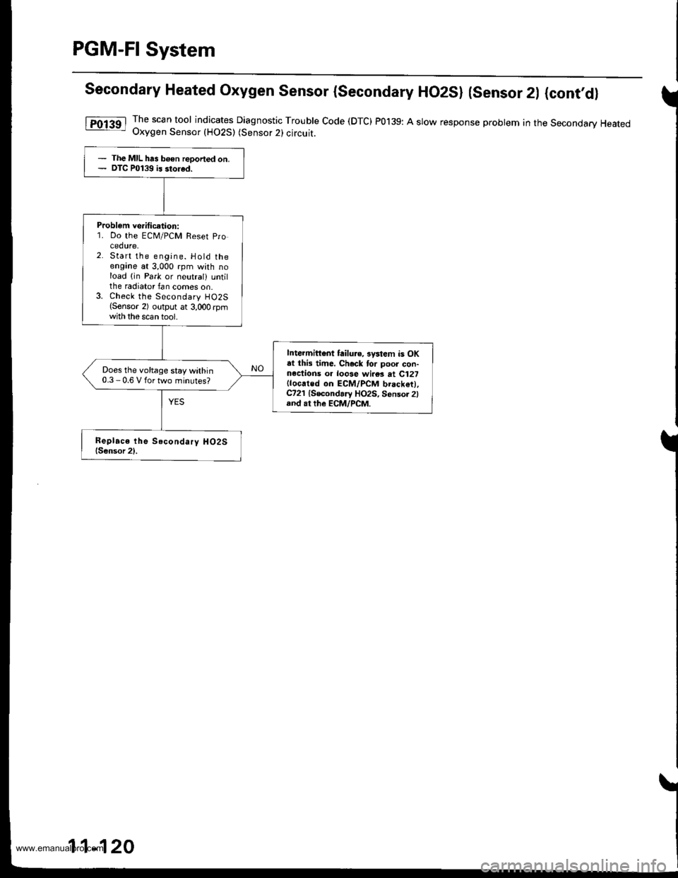
Secondary Heated Oxygen Sensor (secondary HO2SI (sensor 2l (cont,d)
lTol3al The scan tool indicates Diagnostic Trouble Code (DTC) P0139: A slow response probtem in the Secondary Heated- Uxygen Sensor (HO2S) (Sensor 2l circuit.
- The MIL has b€en reoorted on.- DTC P0139 is storad.
Probl€m ve.itication:1. Do the ECM/PCM Reset Procedure,Start the engine. Hold theengine at 3,000 rpm with noload (in Park or neutral) untilthe radiator fan comes on.Check the Secondary HO2S(Sonsor 2) output at 3,000 rpmwith the scan tool.
lntehittont failure, 3ystem is OKat this time. Chock for poor con-nections o. loose wi.es at C127(located on ECM/PCM brack€t),C721 {Secondary HO2S, Sensor 2land at the EcM/PcM.
Does the voltage stay within0.3 - 0.6 V for two minutes?
11-120
www.emanualpro.com
Page 323 of 1395
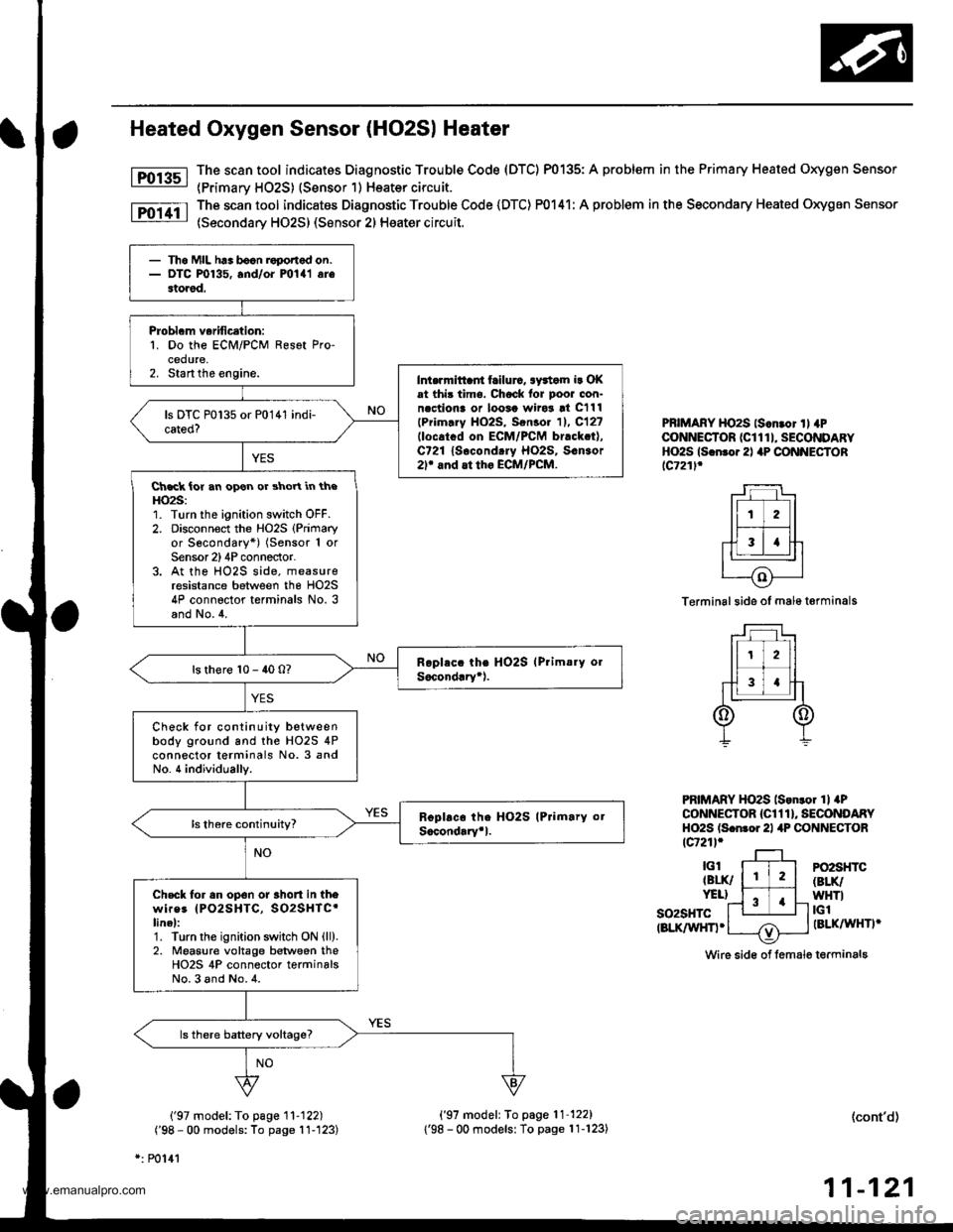
Heated Oxygen Sensor (HO2S| Heater
The scan tool indicatos Diagnostic Trouble Code (DTC) P0135: A problem in the Primary Heated Oxygen Sensor
{Primarv HO2S) (Sensor 1) Heater circuit.
The scan tool indicates Diagnostic Trouble Code (DTC) P0141: A problem in the Secondary Heated Oxygen Sensor
(Secondary HO2S) (Sensor 2) Heater circuit.
Fol3sl
Fo11tl
PBIMARY HO2S ls.n.or ll 4PCONNECTOR (CI 1 1 I, SECONDARYHO2S ls.n.o.2l aP CONNECTORlc721l.
Terminal side of male t€rminals
PRIMARY HO2S lson.o. 1l aPCONNECTOR {Cl 1 1 }, SECONDARYHO2S ls.nror 21 4P CONNECTORtcr21l.
so2sHTctBLK/WHn.
PO2SHTC(BLK/
WHTItGlIBLKAAIHTI'
Wire sid€ of lemale terminals
('97 model: To page '11-122)
('98 - 00 models: To page 11-'123)
*: P0141
('97 model: To page'11-122)
1'98 - 00 modelsl To page 11-123)(cont'd)
11-121
- Th6 MIL h.. bocn roponod on.- DTC P0135, and/oi mlal arestored.
Probl.m verification:1. Do the ECM/PCM Resot Pro-cedure,2. Start the engine.Int.rrnittaii frilurc, awtom ir OKat thi3 time. Chock lor poor con-n.ctiona or loosa wiro3 !t C111
lPrim.ry HO2S, Sen3o. 11. C12?llocatcd on ECM/PCM br.ck.t),C721 lsocond.ry Ho2s, s.n3or2r and at tho ECM/PCM.
Ch.ck ior an opon or shoYt in theHO2S:1. Turn the ignition switch OFF.2. Disconnoct the Ho2s (Primary
or Secondary*) (Sensor 1 orSensor 2)4P conneclor.3. At the HO2S side, measureresistance between the HO2S4P connector terminals No. 3and No.4.
ls there 10 - 40 0?
Check for continuity betweenbody ground and the HO2S 4Pconnector terminals No. 3 andNo. 4 individually.
Check tor an op6n or 3hort in thewires IPO2SHTC, SO2SHTC'linel:1. Turn the ignition swhch ON {ll).2. Moasure voltage between theHO2S 4P connector terminalsNo.3 and No.4.
www.emanualpro.com
Page 324 of 1395
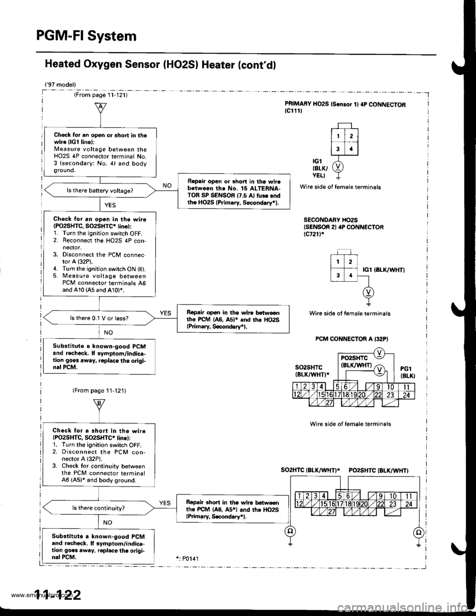
PGM-FI System
Heated Oxygen Sensor IHO2S) Heater (cont'd)
{'97 model)
(From page l1-121)
PRIMARY HO2S (S.nsor 1) ap CONNECTOR{cl111
| 112 ||.�i-l
13 .l
'ot X-tErK/ (9YELI -L
Wire side of female terminals
SECONDARY HO2SISENSOR 21 4P CONNECTORlcr21l,
IGl IBLK/WHTI
Wire side ol female terminals
Wire side of female terminals
So2HTCIALK/WHTI* PO2SHTCIBLK/WHTI
Chock for en open or lhort in thewire (lG1 line):Measure voltage between theHO2S 4P connector terminal No.3 (secondary: No. 4) and bodyground,
Reprir op6n or 3hort in thc wircbetwo.n th€ No. 15 ALTERNA-TOR SP SENSOR (7.5 Al fu!. rndtho HO2S (Primary. Socond.ry*).
Ch€ck for an open in the wire(PO2SHTC, SO2SHTC. lin€):1. Turn the ignition switch OFF.2. Reconnect the HO2S 4P con-
3. Disconnect the PCM connec-tor A (32P).4. Turn the ignition switch ON (ll).5. Measure voltage betweenPCM connector t€rminals 46and A10 (A5 and A10)*.
Bepair opon in the wiro botwoonthe PcM (A6. A5lr and tho Ho2s{Prim.ry, Socond!ryr}.
ls thero 0.1 V or less?
Substitute a lnown-good PCMand recheck. lt 3ymptom/indica-tion goes away, .oplaco the origi-nal PCM.
Check fo. a ahort in the wireIPO2SHTC, SO2SHTC. lins):1. Turn the ignirion switch OFF.2. Disconnect the PCM con-nector A {32P).3. Check lor continuily betweenthe PCM connector terminal46 (A5)* and body ground.
Bopair short in the wire lrotwsentho PC{r4 {A6, A5rl and the HO2SlPiimary, S€condary.l.
Substitute a known-good PCMand .echgck. lf 3ymptom/indica-tion go€s awry. repl.cethe origi-nal PCM.
11-122
www.emanualpro.com