Ac system HONDA CR-V 1998 RD1-RD3 / 1.G Manual PDF
[x] Cancel search | Manufacturer: HONDA, Model Year: 1998, Model line: CR-V, Model: HONDA CR-V 1998 RD1-RD3 / 1.GPages: 1395, PDF Size: 35.62 MB
Page 260 of 1395
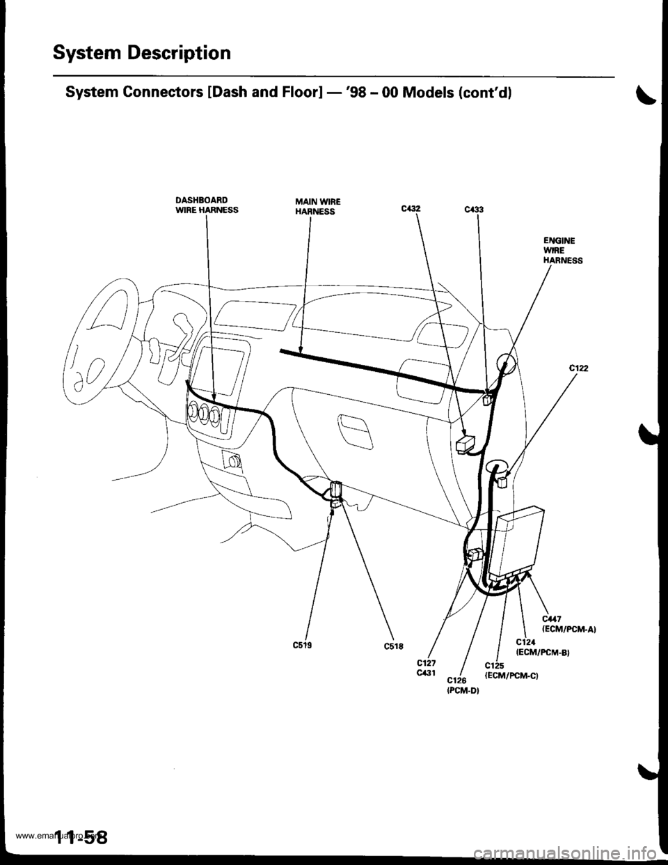
System Description
ENGINEWIREHARNESS
System Conneetors lDash and Floorl -'98 - 00 Models (cont'dl
DASHBOARDWIRE HARNESSMAIN WIB€HARNESS
c,47(ECM/PCM.A}
c121(ECM/PCM-8)
n
lno,
(PCM.D}
www.emanualpro.com
Page 264 of 1395
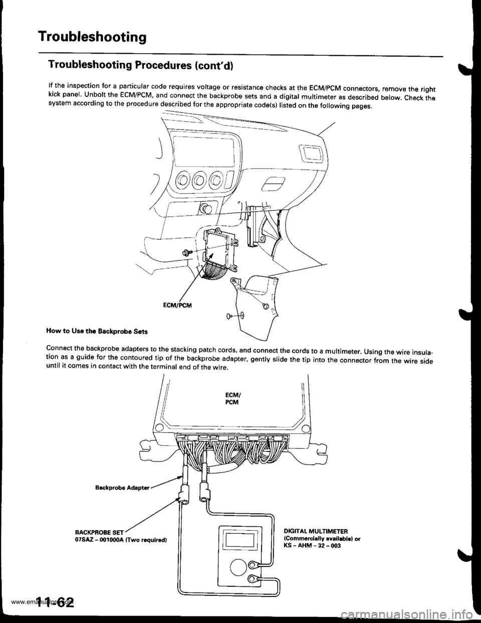
Troubleshooting
Troubleshooting Procedures (cont'd)
lf the inspection for a particular code requires voltage or resistance checks at the EcM/pcM connectors, remove the rightkick panel. Unbolt the EcM/PcM. and connect the backprobe sets and a digital multimeter as described below, check thesystem according to the procedure described for the appropriate code(s) listed on the following pages.
How to Us6 tho Backprobe S6ts
Backp.obo Adapto.
BACKPROBE SET
connect the backprobe adapters to the stacking patch cords. and connect the cords to a multimeter. Using the wire insula-tion as a guide for the contoured tip of the backprobe adapter, gently slide the tip into the connector from the wire sideuntil it comes in contact with the terminal end of the wire.
DIGITAI. MULTIMETER(Commarci.lly rvrilabl.l orKS-AHM-32-@3
@@)@)c,
11-62
o'SAZ - (xtlqDA lTwo requir.dl
www.emanualpro.com
Page 266 of 1395

Troubleshooting
Troubleshooting Procedures (cont'dl
Symptom Chart
Listed below are symptoms and probable causes for problems that DO NOT cause the Malfunction Indicator Lamp (MlL) tocome on. lf the MIL was reported on, go to page 11-60.Troubleshoot each probable cause in the order listed (from left to right) until the symptom is eliminated,The probable cause and troubleshooting page reference can be found below.
Other Probable Causes for an engine that will not start:- Compression- Intake air leakage- Engine locked up- Timing belt- Starting system- Overheating- Battery
SYMPTOMPROBABLE CAUSE
Engine will not sta rt4, 2,3,5,20, 't5, 1
Hard starting2, 4, 12,17, 14, 't9
Cold fast idle too low7, a,9, 6, 17
Cold fast idle too high7,8,9,11,10
ldle speed fluctuates9,7,8, 't1, 10
Misfire or rough runningTroubleshoot for misfire on pages '11-126, 1|21LOl/\/ power2, 10,11, 13, '17, 18,20
Engine stalls2, 4, 12,1,20,9,5, 't6
Probable Cause List (For the DTC Ch8rt, see page ll-75.)
Probable CausePageSystem
Engine controt ruoaute (ecvtffi'I11-42
I 1-178Fuel oressure
PGM-Fl main relav
lgnition system
Crankshatt Position/Top Dead Center/Cylinder position sensor circuit
Intake Air Temperature (lAT) sensor ctrculr
ldle Air Control (lAC) Vatve
Fast idle thermo valve
ldle speed adjustment
Throttle body
Throftle cable
Manifold Absolute P."""rr"ffi
Throftle Position (TP) sensor
Barometric pressur" (gnno-
Ay'T gear position signal
Brake switch signal
Air Cleaner
Three Way Catalytic Converter (TWC)
Evaporative emission (EVAP) control
Contaminated fuel
1 1- 187
Section 4
5't1-'t31,146
6I '�t-95
711-152
81'l-168
1 1- 169
1011-196'1111-'194
12'1 'l -90
1 1- 103
1411-137
15Section 14
161 1- 166
17r 1-194
181 1,199'1911-203
20
11-64
www.emanualpro.com
Page 268 of 1395
Troubleshooting
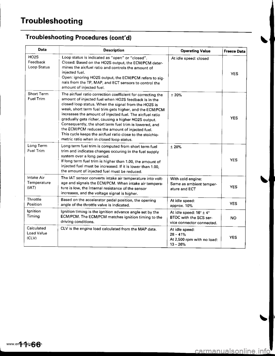
Troubleshooting Procedures (cont'd)
DataDescliptionOperating ValueFreezo Data
HO2S
Feedback
Loop Status
Loop status is indicated as "open" or "closed".
Closed: Based on the HO2S output, the ECM/pCM deter-mines the airlfuel ratio and controls the amount ofinjected fuel.
Open: ignoring HO2S output, the ECM/pCiM refers to sig,nals from the TP, MAP, and ECT sensors to control theamount of injected fuel.
At idle speed: closed
YES
Short Term
Fuel Trim
The airlfuel ratio correction coefficient for correcting theamount of injected fuel when HO2S feedback is in theclosed loop status. When the signal from the HO2S isweak, short term fuel trim gets higher, and the ECM/PCMincreases the amount of injected fuel. The airlfuel ratiogradually gets richer, causing a higher HO2S output.Consequently. the short term fuel trim is lowered. andthe ECM/PCM reduces the amount of injected fuel.This cycle keeps the airfuel ratio close to the stoichio-metric ratio when in closed looD status.
t:20y"
YES
Long Term
Fuel Trim
Long term fuel trim is computed from shon term fueltrim and indicates changes occuring in the fuel supplysystem over a long period.
lf long term fuel trim is higher than 1,00. the amount ofinjected fuel must be increased. lf it is lower than L00.the amount of injected fuel must be reduced.
! 20%
Intake Air
Temperature
(IAT)
The IAT sensor converts intake air temperature into volt-age and signals the ECrU/PCM. When intake air tempera-ture is low, the internal resistance of the sensorincreases, and the voltage signal is higher.
With cold engine:
Same as ambient temper-
ature and ECTYES
Throttle
Position
Based on the accelerator pedal position, the openingangle of the throttle valve is indicateo.At idle speed:
approx. 10%
lgnition
Timing
lgnition timing is the ignition advance angle set by theECM/PCM. The ECM/PCM matches ignition timing to thedriving conditions.
At idle speed: 16'1 4.
BTDC with the SCS ser-
vtce connector connected.
NO
Calculated
Load Value(cLV)
CLV is the engine load calculated from the MAp data.At idle speed:
2A - 410/o
At 2,500 rpm with no load:
13 - 260/o
YES
_
1 1_66
www.emanualpro.com
Page 277 of 1395
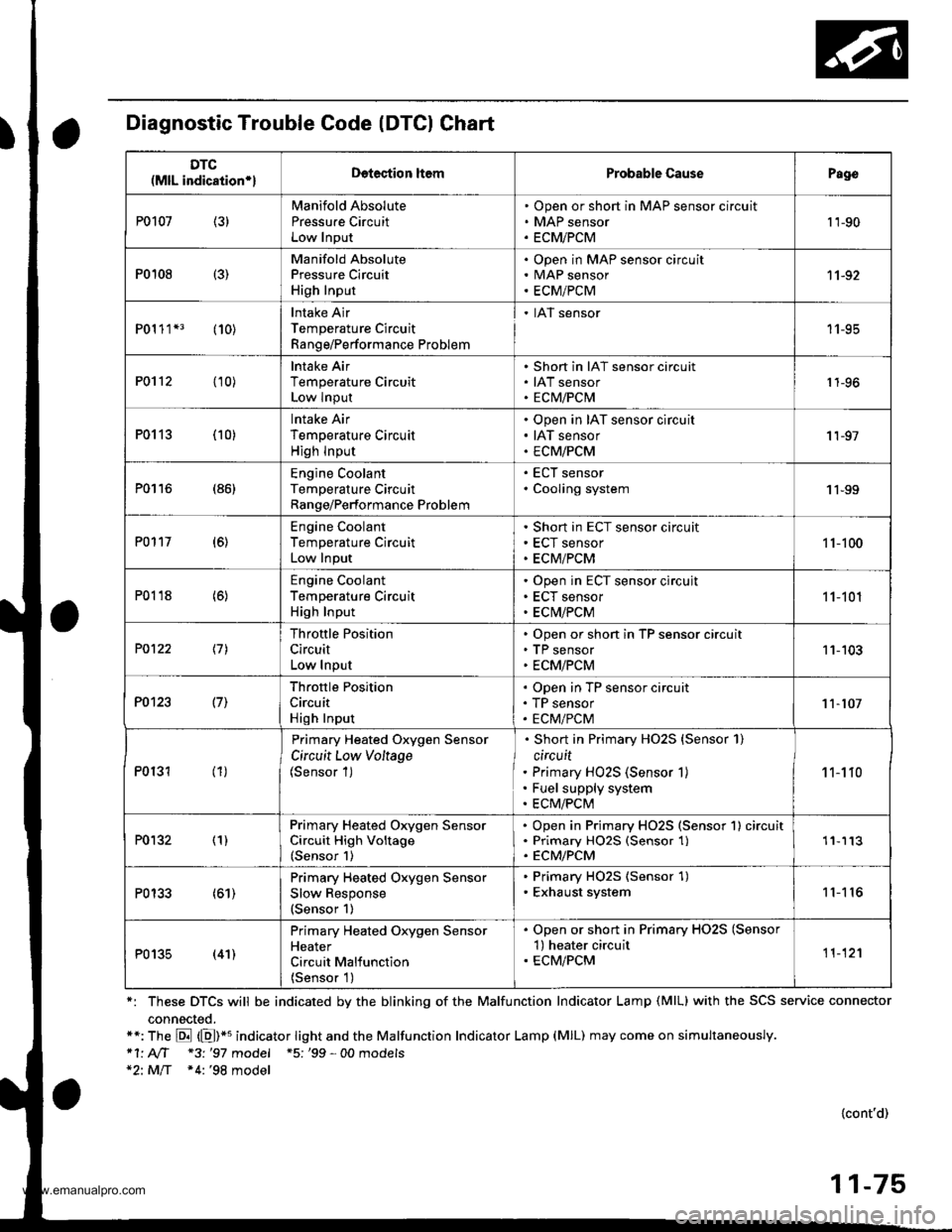
Diagnostic Trouble Code (DTCI Chart
*: These DTCS will be indicated by the blinking of the Malfunction Indicator Lamp (MlL) with the SCS service connector
connected.**: The E (E)*u indicator tight and the Malfunction Indicator Lamp (MlL) may come on simultaneously.*1' AIT *3 '97 model +5; '99 - 00 models*2: MlT *4:'98 model
{cont'd)
11-75
DTC(MlL indication*lDetection ltemProbable CausePago
P0107 (3)Manifold Absolute
Pressu.e CircuitLow Input
Open or short in MAP sensor circuit
MAP sensor
ECMiPCM
't 'l-90
P0108 {3)
Manifold AbsolutePressure Circuit
High Input
Open in MAP sensor circuitMAP sensor
ECM/PCM
11-92
P01 1 1*3 (10)Intake Air
Temperature Circuit
Range/Performance Problem
. IAT sensor
11-95
P0112 (10)lntake Air
Temperature CircuitLow Input
Short in IAT sensor circuit
IAT sensorECM/PCM1 1-96
P0113 (10)lntake Air
Temperature Circuit
High lnput
Open in IAT sensor circuit
IAT sensor
ECM/PCM
'I 1-97
P0116 (86)Engine CoolantTemperature CircuitRange/Performance Problem
ECT sensor
Cooling system1 1-99
P0117 (6)Engine Coolant
Temperature Circuit
Low Input
Short in ECT sensor circuit
ECT sensor
ECM/PCM
1 1-100
P0118 (6)Engine Coolant
Temperature CircuitHigh Input
Open in ECT sensor circujt
ECT sensor
ECM/PCM
11-101
P0122 \11
Throttle Position
Circuit
Low Input
Open or short in TP sensor circuitTP sensor
ECM/PCM
11-103
P0123 l7l
Throftle Position
Circuit
High Input
Open in TP sensor circuit
TP sensor
ECM/PCM11-107
P0131 (1)
Primary Heated Oxygen Sensor
Circuit Low Voltage(Sensor 1)
Short in Primary HO2S {Sensor 1)
circuit
Primary HO2S (Sensor 1)
Fuel supply system
ECM/PCM
1 1-1 10
P0132 (1)Primary Heated Orygen SensorCircuit High Voltage(Sensor 1)
Open in Primary HO2S (Sensor 1) circuitPrimary HO25 (Sensor 1)ECM/PCM
'11113
P0133 (61)Primary Heated Oxygen Sensor
Slow Response(Sensor 1)
. Primary HO2S (Sensor 1). Exhaust system11'I 16
P0135 (41)
Primary Heated Oxygen SensorHeater
Circuit Malfunction
{Sensor 1)
. Open or short in Primary HO2S (Sensor'l) heater circuit. ECM/PCM11-12'l
www.emanualpro.com
Page 278 of 1395
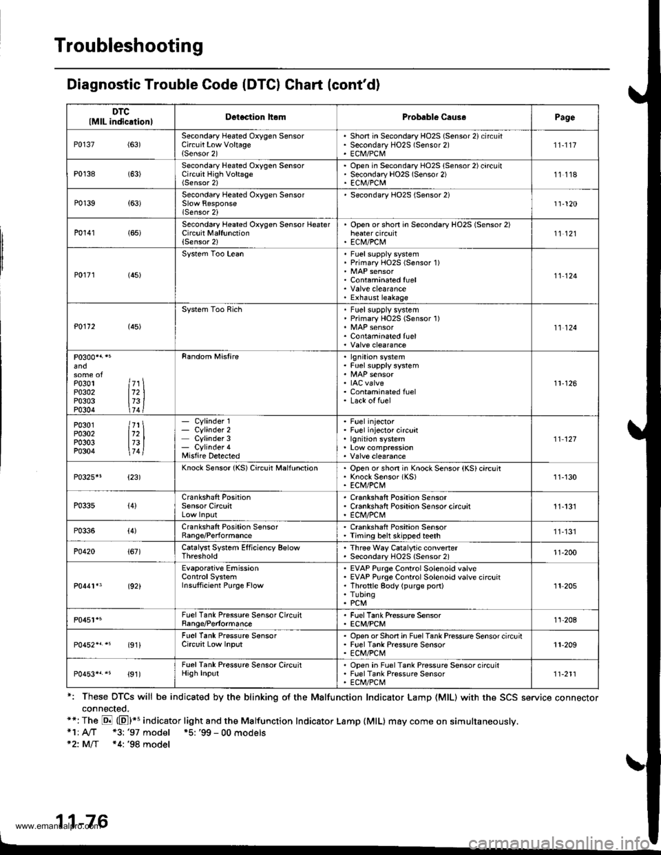
Troubleshooting
Diagnostic Trouble Code (DTCI Chart (cont'd)
*: These DTCS will be indicated by the blinking o{ the Malfunction Indicator Lamp (MlL) with the SCS service connector
connected.**: The E (El*s indicator light and the Malfunction Indicator Lamp {MlL) may come on simultaneously,*1; A/T *3: '97 model *5: '99 - 00 models*2: MlT *4: '98 model
11-76
DTClMlL indicationlDetection hemProbable Caus.Page
P0137(63)Secondary Heated Oxygen SensorCircuit Low Voltage{Sensor 2)
Shon in Secondary HO2S (Sensor 2) circuatSecondary HO2S (Sensor 2)ECM/PCM
'n-1t7
P0138 (63)Secondary Heated Oxygen SensorCircuit High VoltageOpen in Secondary HO2S (Sensor 2) circuitSecondary HO2S (Sensor 2)EC|\il/PCM11118
P0139{63)Secondary Heated Oxygen Sensor
lSensor 2i
Secondary HO2S (Sensor 2)11-120
P0141 (65)Second6ry Heated Oxygen Sensor HeaterCircuit Malfunction(Sensor 2)
Open orshon in Secondary HO2S (Sensor 2)heater circuitEC|V/PCtu11't2l
P0r71 (45)
System Too LeanFuel supply systemPrimary HOzS (Sensor 1)
Contaminated fuel
Exhaust leakage
11124
P0112 (45)
System Too RichFuel supplv systemPrimary HO2S (Sensor 1)
Contaminated fuel11 124
and
Po3ol ltr \P0302 112 |P0303 173 iP0304 \74 t
Random Mistirelgnition systemFuel supply system
IAC valveContaminated fuelLack of fuel
11-126
P0301 /71 \P0302 112 |P0303 173 |P0304 \7 4l
- Cylinder 1- Cylinder 2Cylinder 3- Cylinder 4Misfire Detected
Fuel injectorFuel injector circuitlgnition system't't 127
P0325*5{23)Knock Sensor {KS) Circuit MalfunctionOpen or shon in Knock Sensor (KS) circuitKnock Sensor (KS)ECM/PCt\411-130
P033s{4}Crankshaft PositionSensor CircuitCrankshaft Position SensorCrankshaft Positaon Sensor circuitE Cl\,l/PC l\,'!11-131
P0336(4)Crankshaft Position SensorRange/PerformanceCrankshaft Position SensorTiming belt skipped teeth11,131
P0420{67)Catalyst System Efficiency BelowThresholdThree Way Catalytic convenerSecondary HO2S {Sensor 2)'t1-200
P0441*3 (92)
Evaporative EmissionControlSystemInsulficient Purge Flow
EVAP Purge Control Solenoid valveEVAP Purge Control Solenoid valve circuitThrottle gody (purge port)TubingPCM
'It 205
P0451*5FuelTank Pressure Sensor CircuitBange/PerformanceFuel Tank Pressure SensorECM/PCMt't-208
(91iFuel Tank Pressure SensorCirclit Low InputOpsn orShort in FuelTank Pressure Sensor circuitFuel Tank Pressure SensorECM/PCt\411-209
P0453*r.5 {91)FuelTank Pressure Sensor CircuitHigh InputOpen in Fuel Tank Pressure Sensor circuitFuel Tank Pressure SensorECt /PCt\.111-211
www.emanualpro.com
Page 279 of 1395
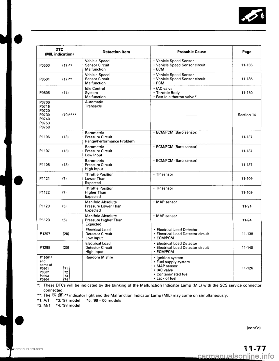
DTC(MlL indicationlDotection ltomProbable CausePage
P0500 t17)*,
Vehicle SpeedSensor CircuitMalfunction
Vehicle Speed SensorVehicle Speed Sensor circu itECtVI1 1-135
P0501 l17J*1
Vehicle SpeedSensor CircuitMalfunction
Vehicle Speed SensorVehicle Speed Sensor circuitPCM11-135
P0505 (14)ldle ControlSystemMalfunction
IAC valveThrottle BodyFast idle thermo valve*11 '�]- 150
P0700P0715PO720P0730P0740P0753P0758
AutomaticTransaxle
Section l4
P1106 (13)BarometricPressure CircuitRange/Performance Problem
ECM/PCM (Baro sensor)
11-137
P1107 (13)BarometricPressure CircuitLow InPut
. ECM/PCM {Baro sensor)11-137
P1108 (13)BarometricPressure CircuitHigh Inpur
ECM/PCM {Baro sensor)11,137
P1121 (7)Throttle PositionLower ThanExpected
. TP sensor11-109
P1122 (7)Throttle PositionHigher ThanExpected
' TP sensor1 1-'109
P112a (5)Manifold AbsolutePressure Lower ThanExpected
. MAP sensor11-94
P1129 (5)Manifold AbsolutePressure HiqherThanExpected
' MAP sensor1l-94
P1297 (20)Electrical LoadDetector CircuitLow Input
Electrical Load DetectorElectrical Load Detector circuitECM/PCM1 1- 138
P1298 (20)Electrical LoadDetector CircuitHigh Input
Electrical Load DetectorElectrical Load Detector circuitECM/PCM11-140
P1300'3
P0301P0302P0303P0304
7l721314
Random lvlisfirelgnition systemFuel supply systemMAP sensorIAC valveContaminated fuelLack offuel
11-126
*: These DTCS will be indicated by the blinking of the Malfunction Indicator Lamp {MlL} with the SCS service connector
connected.**:The E (E])+s indicator light and the Malfunction Indicator Lamp (MlL) may come on simultaneously.*1:A,./T "3: '97 model +5: '99 - 00 models*2: M/T *4:'98 model
{cont'd)
11-77
www.emanualpro.com
Page 280 of 1395
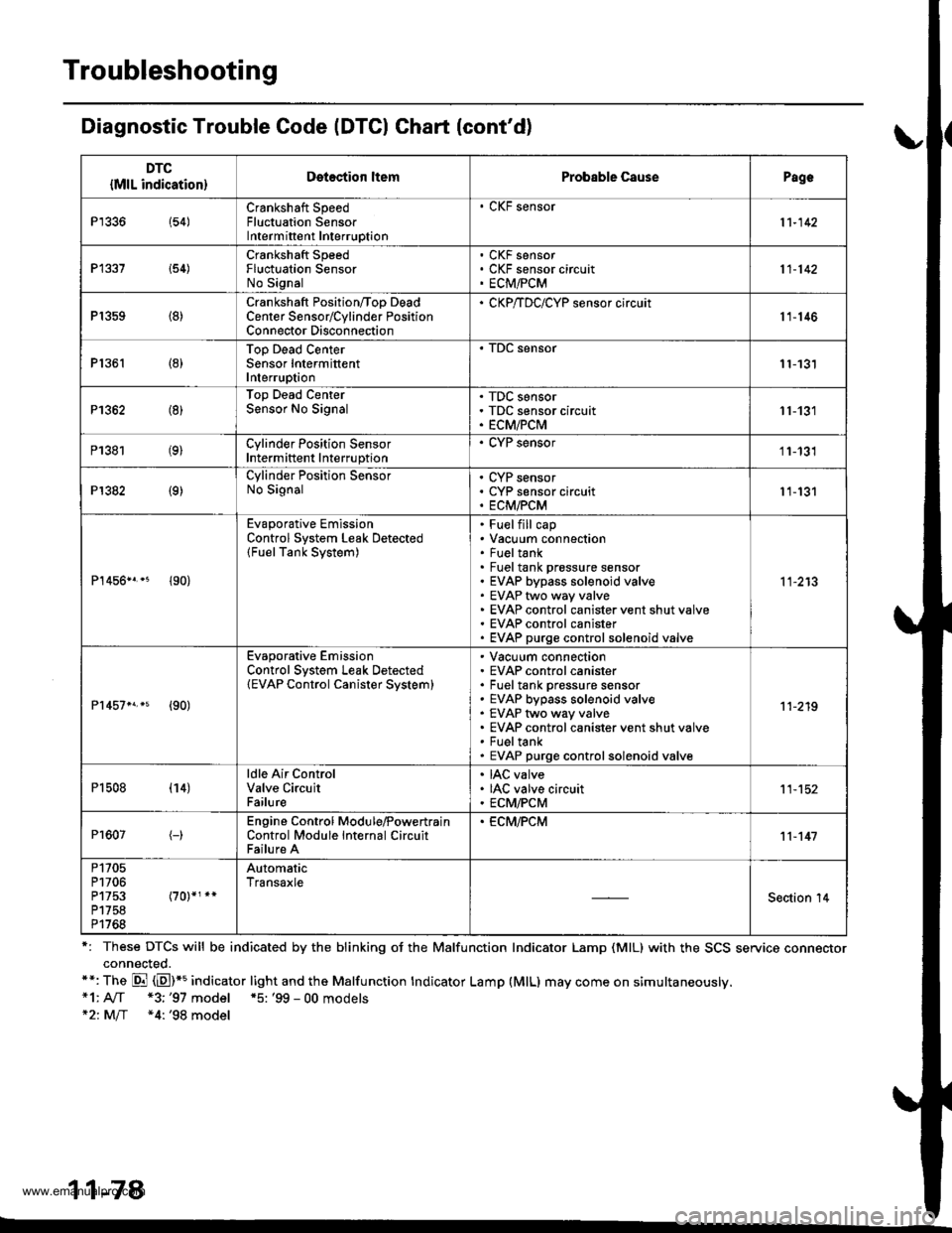
Troubleshooting
Diagnostic Trouble Code (DTCI Ghart (cont'd)
r: These DTCS will be indicated by the blinking oJ the Malfunction Indicator Lamp (MlL) with the SCS service connectorconnected.**: The Di (E)*5 indicator light and the Malfunction tndicator Lamp (MlL) may come on simultaneously.*1: A[f *3;'97 model *5: '99 - 00 models*21M/f *4: '98 model
11-78
DTC
{MlL indication}Detection ltemProbable CausePagc
P1336 154)Crankshaft SpeedFluctuation SensorIntermittent Interruption
. CKF sensor
11-142
P1337 i54)Crankshaft SpeedFluctuation SensorNo Signal
CKF sensorCKF sensor circuitECM,FCM11-142
P1359 (8)Crankshaft Position/Too DeadCenter Sensorrcylinder PositionConnector Disconnection
' CKP/TDC/CYP sensor circuit11-146
P1361 (8)Top Dead CenterSensor IntermittentInterruption11-131
P1362 (8)Top Dead CenterSensor No SignalTDC sensorTDC sensor circuitECM/PCM11-131
P1381 (9)Cylinder Position SensorIntermittent Interruption
. CYP sensor11-131
P1382 (9)Cylinder Position SensorNo SignalCYP sensorCYP sensor circuitECM/PCM11-131
P1456n.* {90}
Evaporative EmissionControl System Leak Detected(FuelTank System)
Fuelfill capVacuum connectionFueltankFuel tank prossure sensorEVAP bypass solenoid valveEVAP two way valveEVAP control canister vent shut valveEVAP control canisterEVAP purge controlsolenoid valve
11-213
Pr457n.s {90)
Evaporative EmissionControl System Leak Detected(EVAP Control Canister Svstem)
Vacuum connectionEVAP control canisterFuel tank pressure sensorEVAP bypass solenoid valveEVAP two way valveEVAP control canister vent shut valveFueltankEVAP purge controlsolenoid valve
11-219
P1508 (14)ldle Air ControlValve CircuitFailure
IAC valveIAC valve circuitECM/PCM11-152
Pr607(-)Engine Control Module,PowertrainControl Module Internal CircuitFailure A
. ECM,FCM11-147
P1705P1706P1753P1758P1768
AutomaticTransaxle
Section '14
www.emanualpro.com
Page 281 of 1395
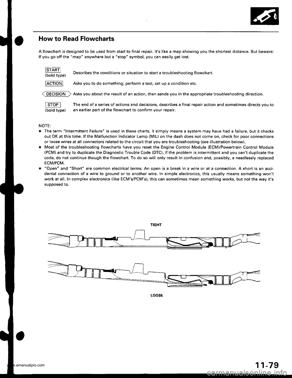
How to Read Flowcharts
A flowchart is designed to be used from start to final repair. lt's like a map showing you the shortest distance. But beware:
lf you go off the "map" anywhere but a "stop" symbol, you can easily get lost.
brARn
t.-OotO tw"t Describes the conditions or situation to start a troubleshooting flowchart.
FcTloNl Asks you to do something; perform a test, set up a condition etc.
@ Asks you about the result of an action, then sends you in the appropriate troubleshooting direction.
fS-OPl The end of a series of actions and decisions, describes a final repair action and sometimes directs you to
(bold type) an earlier part of the flowchart to confirm your repair.
NOTE:
. The term "lntermittent Failure" is used in these charts. lt simply means a system may have had a failure, but it checks
out OK at this time. lf the Malfunction Indicator Lamp (MlL) on the dash does not come on, check for poor connections
or loose wires at all connectors related to the circuit that you are troubleshooting (see illustration below).
. Most of the troubleshooting flowcharts have you reset the Engine Control Module (EcM)/Powertrain Control Module(PCM) and try to duplicate the Diagnostic Trouble Code (DTC). lf the problem is intermittent and you can't duplicate the
code, do not continue though the flowchart. To do so will only result in confusion and, possibly, a needlessly replaced
ECM/PCM,
o "Open" and "Short" are common electrical terms. An open is a break in a wire or at a connection. A short is an acci-
dental connection of a wire to ground or to another wire. ln simple electronics, this usually means something won't
work at all. In complex electronics (like ECM'S/PCM'S), this can sometimes mean something works, but not the way it's
suooosed to.
LOOSE
11-79
www.emanualpro.com
Page 282 of 1395

PGM-FI System
System Description
INPUTS
CKP/TDC/CYP Sensor
CKF Sensor
MAP Sensor
ECT Sensor
IAT Sensor
TP Sensor
Primary HO2S
Secondary H02S
vss
KS*5
BARO Sensor
ELD*6
Starter Signal
ALT FR Signal
Air Conditioning Signal
Ay'T Gear Position Signal*1
Baftery Voltage (lGN.1)
Brake Switch Signal
PSP Switch Signal
Fuel Tank Pressuae Sensor*4. *5
Countershaft Speed Sensor*1
Mainshaft Speed Sensor*r
OVER-DRIVE Switch Signal*s
ENGINE CONTROL MODULE (ECM)/
POWERTRAIN CONTROL MODULE (PCM) OUTPUTS
|iuel 1"j""- Th,rhg ""d Drrafr";-l
Et*-.nt"tdt"cont.orl
to,r*,c;;trffi;]
l.----.---:. .Lrgnrnon |lmrng Lonrror I
Ecir/PcM B*k',p Fr""il]
m;"t-ll-r*'io*l
Fuel Injectors
PGM-Fl Main Relay (Fuel Pump)
MIL
IAC Valve
Ay'C Compressor Clutch Relay
Radiator Fan Relay
Condenser Fan Relay
ALT
tcM
EVAP Purge Control Solenoid
Valve
Primary HO2S Heater
Secondary H02S HeaterEVAP Bypass Solenoid Valve*a *5
EVAP Control Canister Vent Shut
DLC
Lock-up Control Solenoid Valve*l
Shift Control Solenoid Valve*1
Ay'T Clutch Pressure Control
Solenoid Valve*1
D4 Indicator Light'1 *3, *a
D Indicator Light,l *5
OVER-DRIVE OFF Indicator
Lighl*t *:
*1: A/T {3:'97 model'2: M/f +4:'98 model*5: '99 - 00 models"6: USA
PGM-Fl System
The PGM-Fl system on this model is a sequential multiport fuel injection system.
Fuel iniecior Timing and Duration
The ECM/PCM contains memories for the basic discharge durations at various engine speeds and manifold pressure. The
basic discharge duration, after being read out from the memory, is further modified by signals sent from various sensors
to obtain the final discharge duration.
ldle Air Control
ldle Air Control Valve (lAC Valve)
When the engine is cold, the Ay'C compressor is on, the transmission is in gear, the brake pedal is depressed, the P/S load
is high, or the alternator is charging, the ECM/PCM controls current to the IAC Valve to maintain the correct idle speed.
lgnition Timing Control
o The ECM/PCM contains memories for basic ionition timing at various engine speeds and manifold air flow rates.
lgnition timing is also adjusted for engine coolant temperature.
. A knock control system was adopted which sets the ideal ig nition timing for the octane rating of the gasoline used.*s
Other Control Funstions
1. Starting Control
When the engine is started. the ECM/PCM provides a rich mixture by increasing fuel injector duration.
2. Fuel Pump Control
. When the ignition switch is initially turned on (ll). the ECMiPCM suppli€s ground to the PGM-FI main relay that
supplies current to the fuel pump for two seconds to pressurize the fuel system.
. When the engine is running, the ECM/PCM supplies ground to the PGM-FI main relay that supplies current to the
fuel oumo.
. When the engine is not running and the ignition is on, the ECM/PCM cuts ground to the PGM-FI main relay which
cuts current to the fuel pump.
1 1-80
www.emanualpro.com