Rack HONDA CR-V 1998 RD1-RD3 / 1.G Manual PDF
[x] Cancel search | Manufacturer: HONDA, Model Year: 1998, Model line: CR-V, Model: HONDA CR-V 1998 RD1-RD3 / 1.GPages: 1395, PDF Size: 35.62 MB
Page 767 of 1395
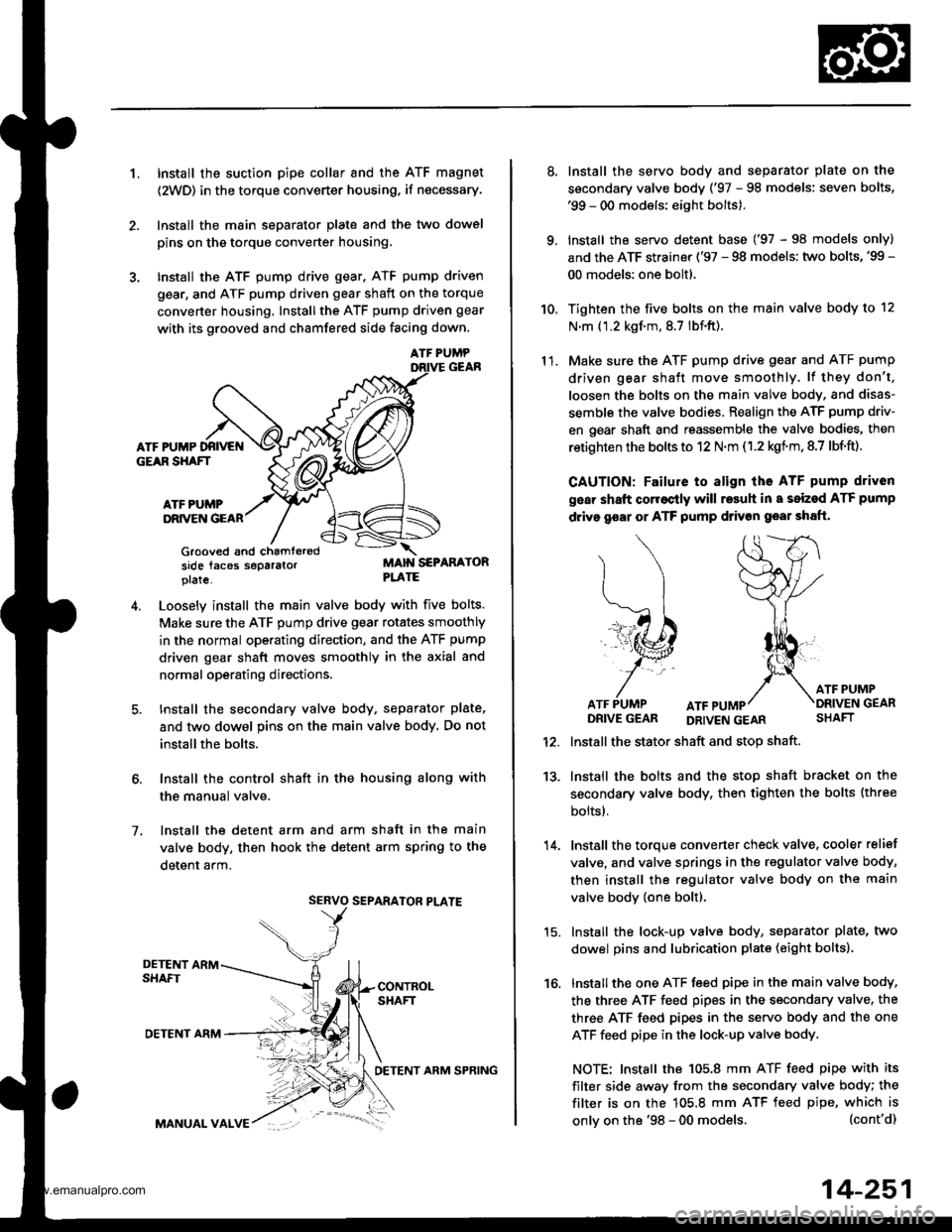
1.Install the suction pipe collar and the ATF magnet
{2WD) in the torque converter housing, if necessary.
lnstall the main seDarator Dlate and the two dowel
pins on the torque converter housing,
Install the ATF pump drive gear. ATF pump driven
gear, and ATF pump driven gear shaft on the torque
converter housing. Installthe ATF pump driven gear
with its grooved and chamfered side facing down.
ATF PUMPGEAR
ATF PUMP D{IVEf{GEAR SHAFT
ATF PUi'PORIVEN GEAR
Grooved and chamteredside faces separatorplate.
MAIN S€PAR/ATORPLATE
5.
o.
Loosely install the main valve body with five bolts.
Make sure the ATF pump drive gear rotates smoothly
in the normal operating direction, and the ATF pump
driven gear shaft moves smoothly in the axial and
normal operating directions.
Install the secondary valve body, separator plate,
and two dowel pins on the main valve body. Do not
installthe bolts.
Install the control shaft in the housing along with
the manual valve.
lnstall the detent arm and arm shaft in the main
valve body, then hook the detent arm spring to the
detent arm.
SEBVO SEPARATOR PLATE
7.
DETENT ARMSHAFT
OETENT ARM
CONTROLSHAFT
MANUAL VAIVE
OETENT ARM SPRING
onlv on the '98 - 00 models,
14-251
1l.
9.
8.
10.
Install the servo body and separator plate on the
secondary valve body ('97 - 98 models: seven bolts,'99 - 00 models: eight bolts).
lnstall the servo detent base ('97 - 98 models only)
and the ATF strainer ('97 - 98 models: two bolts,'99 -
00 models: one boltl.
Tighten the five bolts on the main valve body to 12
N'm (1.2 kgf.m, 8.7 lbf.ft).
Make sure the ATF pump drive gear and ATF pump
driven gear shaft move smoothly. lf they don't,
loosen the bolts on the main valve body, and disas-
semble the valve bodies. Realign the ATF pump driv-
en gear shaft and reassemble the valve bodies, then
retighten the bolts to 12 N.m (1.2 kgim, 8.7 lbf.ft).
CAUTION: Failure to align the ATF pump driven
gear shaft corroctly will rosult in a seizsd ATF pump
drive gear or ATF pump drivon gear shaft.
ATF PUMP ATFGEARDRIVE GEAR DBIVEN GEARSHAFT
Install the stator shaft and stop shaft
Install the bolts and the stop shaft bracket on the
secondary valve body, then tighten the bolts (three
bolts).
Install the torque converter check valve, cooler relief
valve, and valve springs in the regulator valve body,
then install the regulator valve body on the main
valve body {one boltl.
Install the lock-up valve body, separator plate, two
dowel pins and lubrication plate (eight bolts).
Installthe one ATF feed pipe in the main valve body,
the three ATF feed pipes in the secondary valve, the
three ATF feed pipes in the servo body and the one
ATF feed pipe in the lock-up valve body.
NOTE: lnstall the 105.8 mm ATF feed pipe with its
filter side away from the secondary valve body; the
filter is on the 105.8 mm ATF feed pipe, which is(cont'd)
13.
14.
15.
16.
www.emanualpro.com
Page 769 of 1395
17.
18.
19.
20.
21.
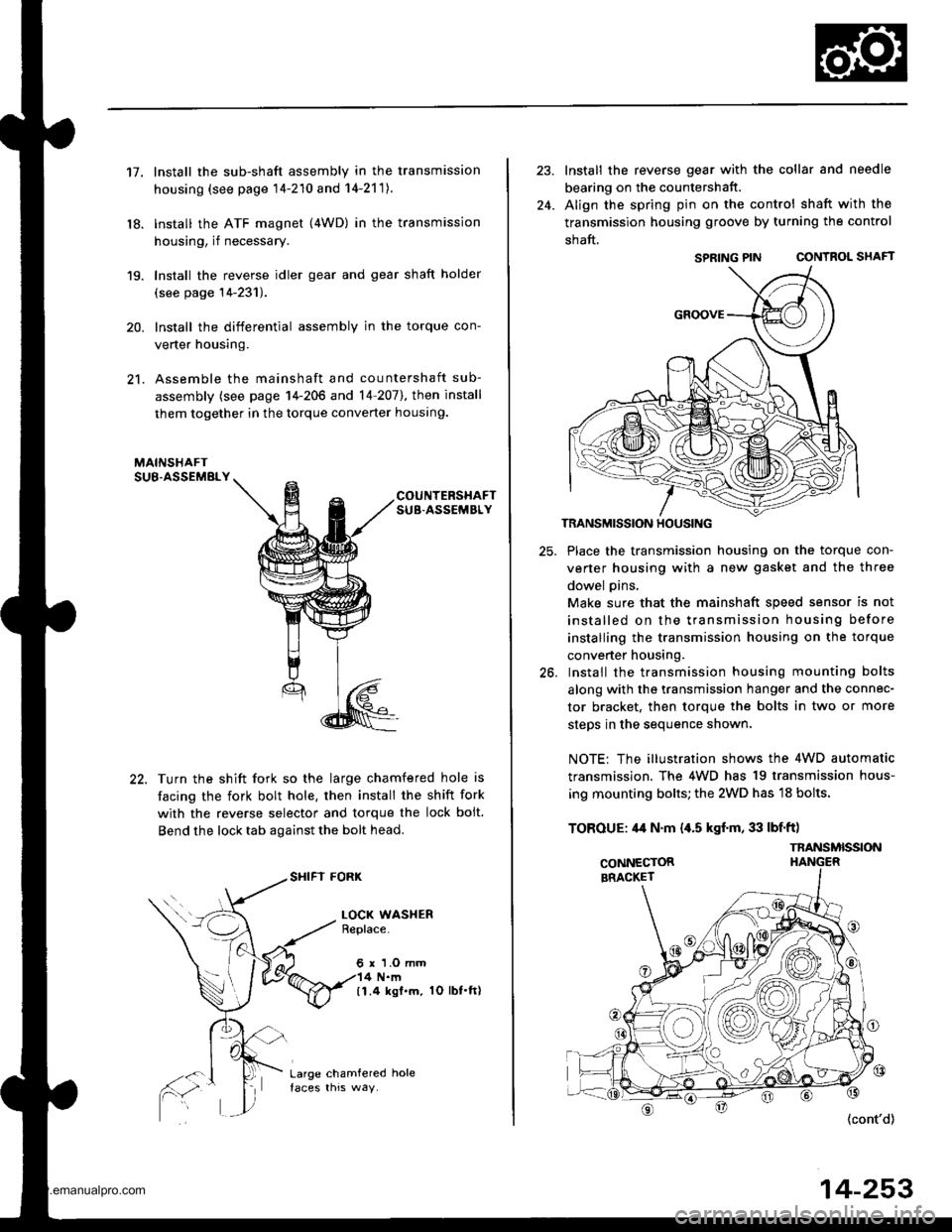
Install the sub-shaft assembly in the transmission
housing (see page 14-210 and 14-2'111.
lnstall the ATF magnet (4WD) in the transmission
housing, if necessary.
Install the reverse idler gear and gear shaft holder
(see page 14-231).
Install the differential assembly in the torque con-
verter housing.
Assemble the mainshaft and countershaft sub-
assembly (see page 14-206 and 14 207],, then install
them together in the torque converter houslng.
COUNTERSHAFTSUB-ASSEMBLY
Turn the shift fork so the large chamfered hole is
facing the fork bolt hole. then install the shift fork
with the reverse selector and torque the lock bolt.
Bend the lock tab against the bolt head.
SHIFI FORK
LOCK WASHERBeplace.
6 r 'l.O mm4 N.m(1.4 ksl.m. 1O lbt.ft)
Large chamfered hole
24.
Install the reverse gear with the collar and needle
bearing on the countershatt.
Align the spring pin on the control shaft with the
transmission housing groove by turning the control
shaft.
SPRING PIN CONTROL SHAFT
TRANSMISSION HOUSING
25. Place the transmission housing on the torque con-
verter housing with a new gasket and the three
dowel pins,
Make sure that the mainshaft speed sensor is not
installed on the transmission housing before
installing the transmission housing on the torque
converter housing.
26. Install the transmission housing mounting bolts
along with the transmission hanger and the connec-
tor bracket, then torque the bolts in two or more
steos in the seouence shown.
NOTE: The illustration shows the 4WD automatic
transmission. The 4WD has 19 transmission hous-
ing mounting bolts; the 2WD has 18 bolts.
TOROUE: 44 N.m {,[.5 kgf.m, 33 lbf'ft)
{cont'd)
14-253
SPRING PIN
TNANSMISSION
www.emanualpro.com
Page 775 of 1395
Transmission
1.
lnstallation
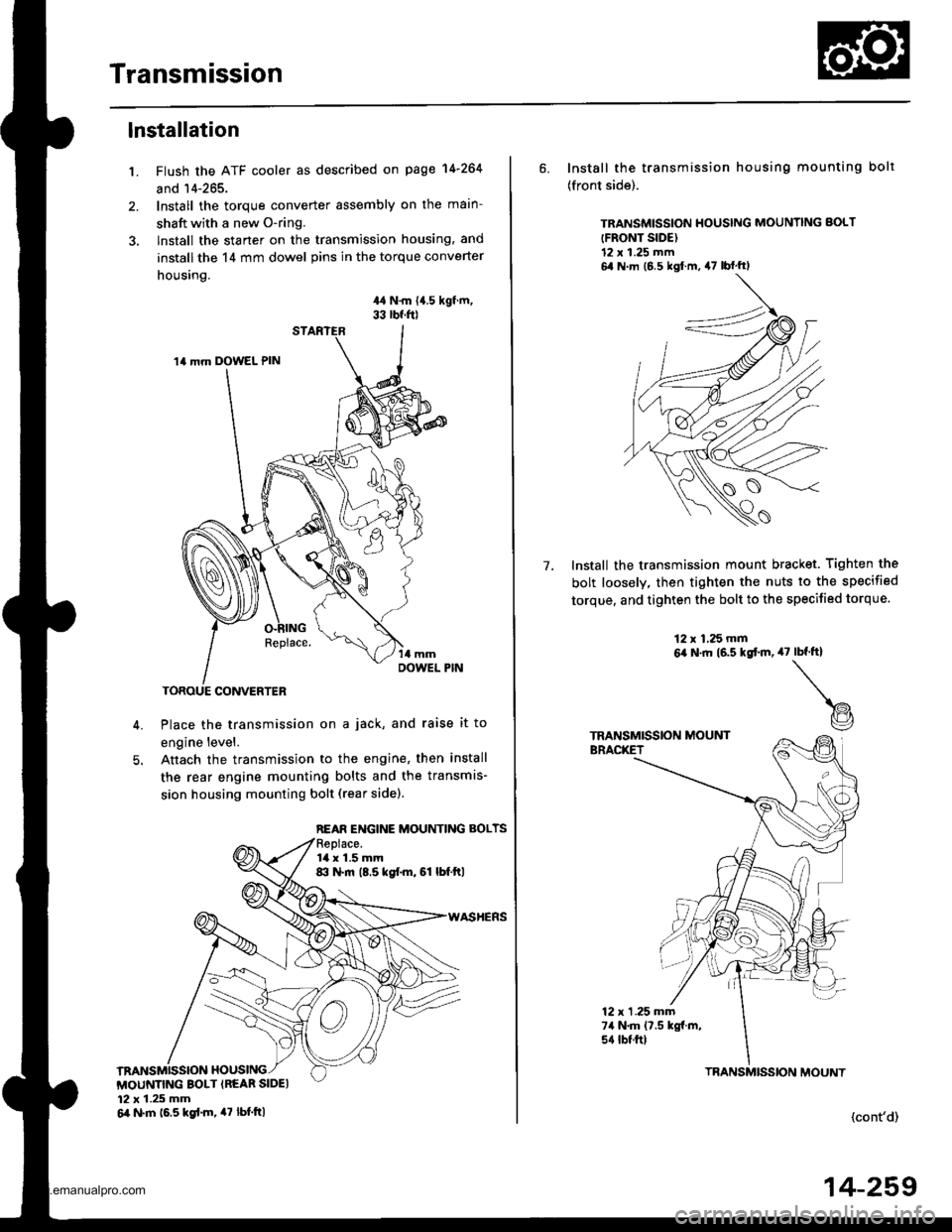
Flush the ATF cooler as described on page 14-264
and 14-265.
Install the torque converter assembly on the main-
shaft with a new O-ring.
lnstall the starter on the transmission housing, and
install the 14 mm dowel pins in the torque converter
housing.
44 N.m {{.5 kgf.m,33 rbf.f0
Place the transmission on a jack, and raise it to
engine level.
Anach the transmission to the engine, then install
the rear engine mounting bolts and the transmis-
sion housing mounting bolt (rear sidel.
14 mm DOWEL PIN
REAR ENGINE MOUNTING BOLTS
la x 1.5 mm8:l N.m (8.5 kgf.m, 61 lbf.ftl
MOUNTING BOLT {REAR SIDEI12 x 1.25 mm6il N.m 16.5 kgd.m, 47 tbt.ttl
6. Install the transmission housing mounting bolt
(front side).
TRANSMISSION HOUSING MOUNNNG BOLT
{FRONT SIDE)12 x 1.25 mm6,1 N m (6 5 kgl m, 47 lbf'ftl
Install the transmission mount bracket. Tighten the
bolt loosely, then tighten the nuts to the specified
torque, and tighten the bolt to the specified torque.
7.
12 x 1,25 mm6,a N.ft (6.5 kgtm,47rbf.ft)
t@
TRANSMISSION MOUNTBRACKET
12 x 1 .25 mm74 N.m (7.5 kgf.m,s{ tbtftl
(cont'd)
TBANSMISSION MOUNT
14-259
www.emanualpro.com
Page 776 of 1395
Transmission
Installation (cont'dl
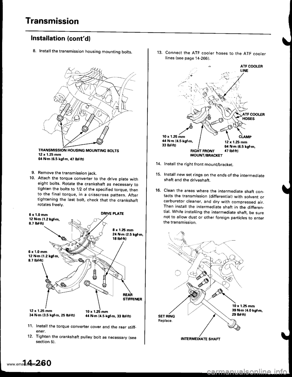
8. Install the transmission housing mounting bolts.
TRANSMISSION HOUSING MOUNTING BOLTS12 x 1.25 mm54 N.m 16,5 kgf.m, a7 lbtftl
9. Remove the transmission jack.
10. Attach the torque convener to the drive plate witheight bolts. Rotate the crankshaft as necessarv totighten the bolts to 'll2 of the specified torque, thento the final torque, in a crisscross pattern. Aftertightening the last bolt. check that the crankshaftrotates freelv.
6x1.0mln12 N.m (1.2 tgt m,8.t lbf.frl
6x1.0mm12 N.m {1.219{.m,8.7 tbtft,
12 x t.25 mm34 N.m 13.5 kgf.rn,25 lbf.ft)
8 x 1.25 mm2a N.m 12.5 kgf'm,18 tbt.ftl
DRIVE PLATE
STIFFENER
44 N.rn (4.5 kgt m, 33 lbtftl
11.
12.
Install the torque convener cover and the rear stiff_ener.
Tighten the crankshaft pulley bolt as necessary (seesection 5).
14-260
13. Connect the ATF cooler hoses to the ATF coolerlines (see page 14-266).
. ATF COOLERLINE
'i 'l'r',:,.) -
10 x 1.25 mm44 N.m (4.5 kgf.m,33 tbtftl
CLAMP
12 x 1.25 mm64 N.m 16.5 kg{.m,a7 tbt.ftlFRotrtT
15.
16.
't 4.
SET RINGReplace.
MOUNT/ARACKET
Install the right front mounvbracket.
Install new set rings on the ends of the intermediateshaft and the driveshaft.
Clean the areas where the intermediate shaft con_tacts the transmission {differential) with solvent orcarburetor cleaner, and dry with compressed air.Then install the intermediate shaft in the differen_tial, While installing the intermediate shaft, be surenot to allow dust or other foreign panicles to enterthe transmission.
l0 x 1.25 mm39 N.m 14.0 kgt.n,29 tbf.ftl
INTERMEDIATE SHAFT
www.emanualpro.com
Page 779 of 1395

26. Connect the vehicle speed sensor (VSS). the coun-
tershaft speed sensor. and the A,/T gear position
switch connectors,
VEHICLE SPEEO
SPEED SENSOACO'{NECTOR
Connect the lock-up control solenoid valve connec-
tor, then install the harness clamp on the clamp
bracket.
HARNESS CI-AMP
27.
RADIATOR HOSECLAMP
TRANSMISSIONGROUND CAB1ITERMINAL
LOCK-UP OONTROLSOLENOID VALVECONNECTOR
6x1.0mm12 N'm (1.2 kgi.m,8.? tbtftl
28.
29.
Instail the transmission ground cable terminal on
the transmission hanger, and install the radiator
hose clamp on the transmission hanger,
Connect the starter cables to the starter, and install
the harness clamD on the clamD bracket. Make sure
the crimped side of the starter cable ring terminal is
facing out.
STARTEBCABLE
STARTER CAAtf,
Install the air cleaner housing assembly and the
intake air duct.
Refill the transmission with ATF (see page 14-161).
Connect the battery positive terminal and negative
terminal.
Set the parking brake, Start the engine, and shift the
transmission through all gears three times.
Check the shift cable adjustment (see page 14-271]-.
Check the tront wheel alignment and adjust it if
needed (see section 18).
Let the engine reach normal operating temperature
(the radiator fan comes on) with the transmission in
E or N position, then turn it off and check the ATF
level {see page 14-160).
Perform a road test (see page 14-157 and 14-158).
30.
31.
34.
CLAMP BRACKET
37.
14-263
www.emanualpro.com
Page 780 of 1395
Transmission
Cooler Flushing
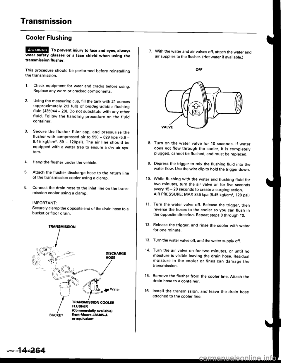
@@ To prevent in;ury to face and eyos, atwayswear safety glasses ot a face shield when using thetlansmission flusher.
This procedure should be performed before reinstallingthe transmission.
2.
LCheck equipment for wear and cracks before using.Replace any worn or cracked components.
Using the measuring cup. fill the tank with 21 ounces{approximately 213 lull) ol biodegradable flushingfluid (J35944 - 20). Do not substitute with any otherfluid. Follow the handling procedure on the fluidcontaaner.
Secure the flusher filler cap, and pressurize theflusher with compressed air to 550 - 829 kpa (5.6 _
8.45 kgf/cm,, 80 - 120psi). The air line should beequipped with a water trap to ensure a dry air sys-tem.
Hang the flusher under the vehicle.
Attach the flusher discharge hose to the return lineof the transmission cooler using a clamp.
Connect the drain hose to the inlet line on the trans-mission cooler using a clamp.
IMPORTANT:
Securely clamp the opposite end ofthe drain hose to abucket or floor drain.
DISCHARGEHOSE
tAirlp Water
TnAI{SrfiSStoN coot"€RFLUSHER{Comm.rcidly.v.il.bt.lK.r -Moor. J38,t{15.Aor aquival.nt
5.
14-264
7. With the water and air valves off, attach the water andair supplies to the flusher. (Hot water if available.)
10.
8.
1'�I.
Turn on the water valve for 1O seconds. lf waterdoes not flow through the cooler, it is completelyplugged, cannot be flushed, and must be replaced.
Depress the trigger to mix the flushing fluid into thewater flow. Use the wire clip to hold the trigger down.
While flushing with the water and flushing fluid fortwo minutes, turn the air valve on for five secondsevery 15 - 20 seconds to create a surging action.AIR PRESSURE: MAX 845 kpa (8.45 kgf/cmr, t20 psi)
Turn the water valve off. Release the trigger, thenreverse the hoses to the cooler so you can flush inthe opposite direction. Repeat steps 8 through 10.
Release the trigger, and rinse the cooler with wate.for one minute.
Turn the water valve off, and the water supply off.
Turn the air valve on for two minutes, or until nomoisture is visible leaving the drain hose. Residualmoisture in the cooler or lines can damage thetransmission.
Remove the flusher from the cooler line. Attach thedrain hose to a container.
Install the transmission, and leave the drain hoseattached to the cooler line.
12.
13.
14.
to.
www.emanualpro.com
Page 784 of 1395
Shift Lever
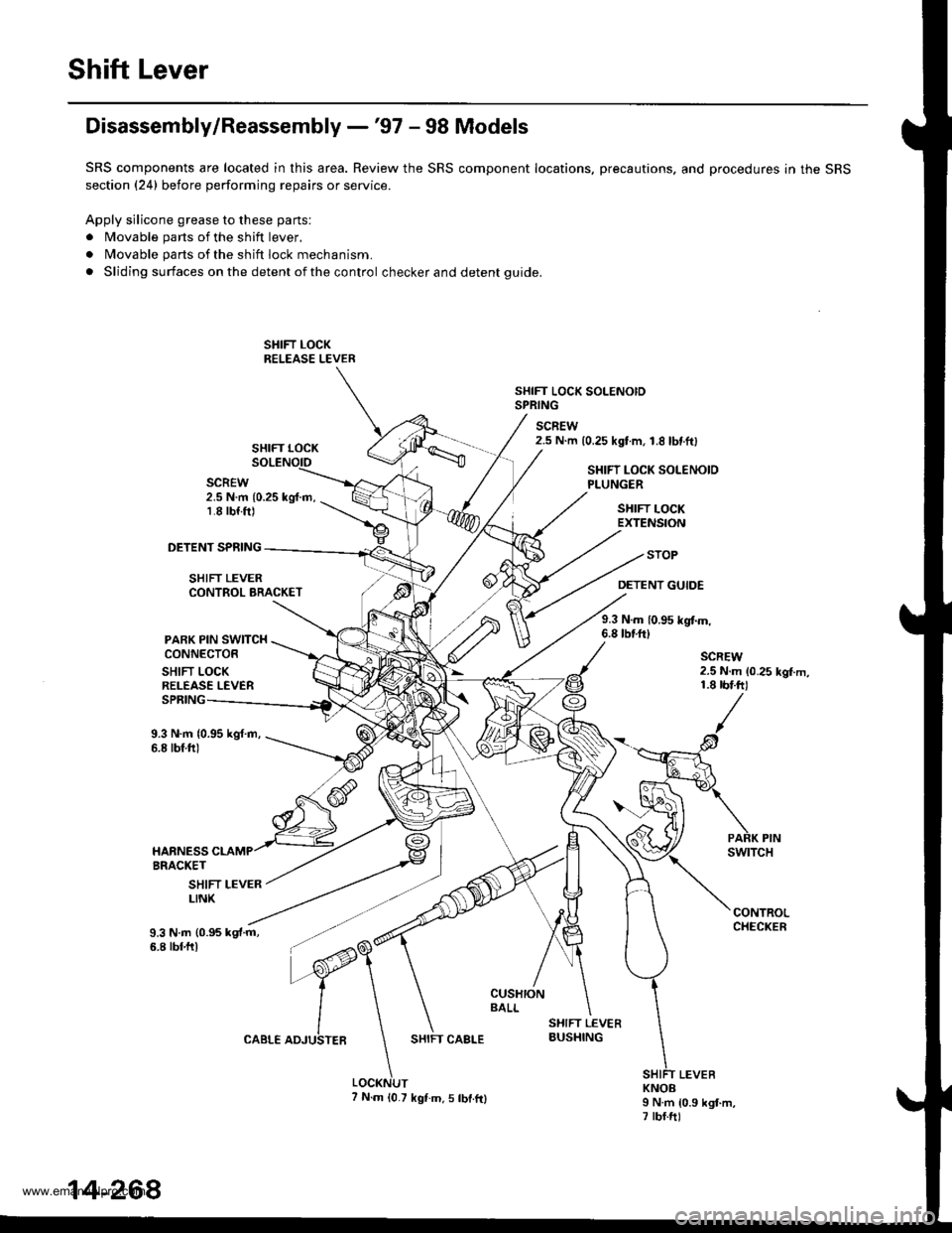
Disassembly/Reassembly -'97 - 98 Models
SRS components are located in this area. Review the SRS component locations. precautions. and procedures in the SRS
section (24) before performing repairs or service.
Apply silicone grease to these parts'
. Movable parts of the shift lever,
. Movable parts of the shift lock mechanism.
. Sliding surfaces on the detent of the control checker and detent guide.
SHIFT LOCK SOLENOIDSPRING
SCREW
SHIFT LOCK2.5 N.m {0.25 kgtm, 1.8 lbtftl
SCREW2.5 N.m {0.25 kg{.m,1.8 rbf.ft)
SHIFT LOCK SOLENOIDPLUNGER
SHIFT LOCKEXTENSION
DETENT SPFING
SHIFT LEVER
PARK PIN SWITCHCONNECTOR
SHIFT LOCKRELEASE LEVER
CONTROL BRACKET
STOP
DETENT GUIDE
9.3 N.m 10.95 kgtm,6.8 tbrft)
SPRING
9.3 N.m {0.95 kgf.m,6.8 tbf.ftl
SHIFT LEVERLINK
9.3 N.m (0.95 kgt.m,6.8 tbf.ftl
SHIFT CAALE
KNOBI N.m 10.9 kgt.m,7 rbf.ftl
14-268
7 N.m {0.7 kgf.m.5 tbt.fr}
www.emanualpro.com
Page 785 of 1395
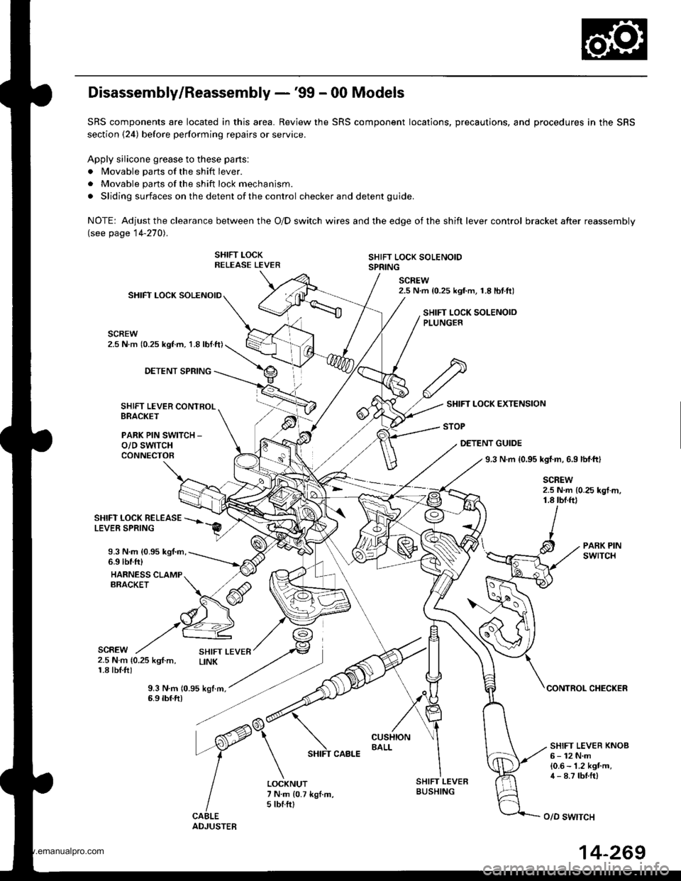
Disassembly/Reassembly -'99 - 00 Models
SRS components are located in this area. Review the SRS component locations, precautions, and procedures in the SRS
section (24) before performing repairs or service.
Apply silicone grease to these parts:
. Movable parts of the shift lever.
. Movable parts of the shift lock mechanism.
. Sliding surfaces on the detent of the control checker and detent guide.
NOTE: Adjustthe clearance between the O/D switch wires and the edge ofthe shift lever control bracket after reassembly(see page 14-270).
SHIFT LOCKRELEASE LEVERSHIFT LOCK SOLENOIDSPRING
SCREW2.5 N.m {0.25 kgf.m, 1.8lbtft)SHIFT LOCK SOLENOID
SCREW2.5 N.m (0.25 kgl.m, 1.8 lbl.ft)
SHIFT LOCK SOLENOIOPLUNGER
DETENT SPRING
SHIFT LEVER CONTROLBRACKET
PARK PIN SWITCH _
o/D swtTcHCONNECTOB
SHIFT LOCK EXTENSION
STOP
DETENT GUIDE
9.3 N.m {0.95 kgf.m, 6.9 lbl.ftl
SCREW2.5 N.m {0.25 kgt m,1.8 tbf.ftl
SHIFT LOCK BELEASELEVER SPRING
9.3 N.m {0.95 kgl.m,6.9 lbtfr)
HARNESS CLAMPERACKET
PARK PINswrTcH
SCREW2.5 N.m {0.25 kgf.m,1.8 tbl.f0
9.3 N.m 10.95 kgtm,6.9 tbf.ft)CONTROL CHECKER
SHIFT LEVER KNOB6- 12 N.m{0.6 - 1.2 kgt'm,4 - 8.7 tbnft)LOCKNUT7 N.m {0.7 kgl.m,5 tbf.ftl
SHIFT LEVERBUSHING
o/D swtTcH
14-269
www.emanualpro.com
Page 786 of 1395
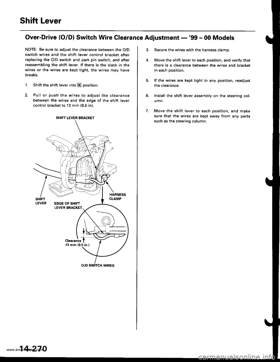
Shift Lever
Over-Drive (O/Dl Switch Wire Clearance Adjustment -'99 - 00 Models
NOTE: Be sure to adjust the clearance between the O/D
switch wires and the shift lever control bracket after
replacing the O/D switch and park pin switch, and after
reassembling the shift lever. lf there is the slack in the
wires or the wires are kept tight, the wires may have
Dreaks.
1. Shift the shift lever into E positron.
2. Pull or push the wires to adjust the clearance
between the wires and the edge of the shift lever
control bracket to 13 mm (0.5 in).
SHIFT LEVER BRACKET
14-270
7.
Secure the wires with the harness clamp.
Move the shift lever to each position, and verify that
there is a clearance between the wires and bracket
in each position.
lf the wires are kept tight in any position, read.iust
the clearance.
Install the shift lever assembly on the steering col-
umn.
Move the shift lever to each position, and make
sure that the wires are kept away from any parts
such as the steering column.
www.emanualpro.com
Page 787 of 1395
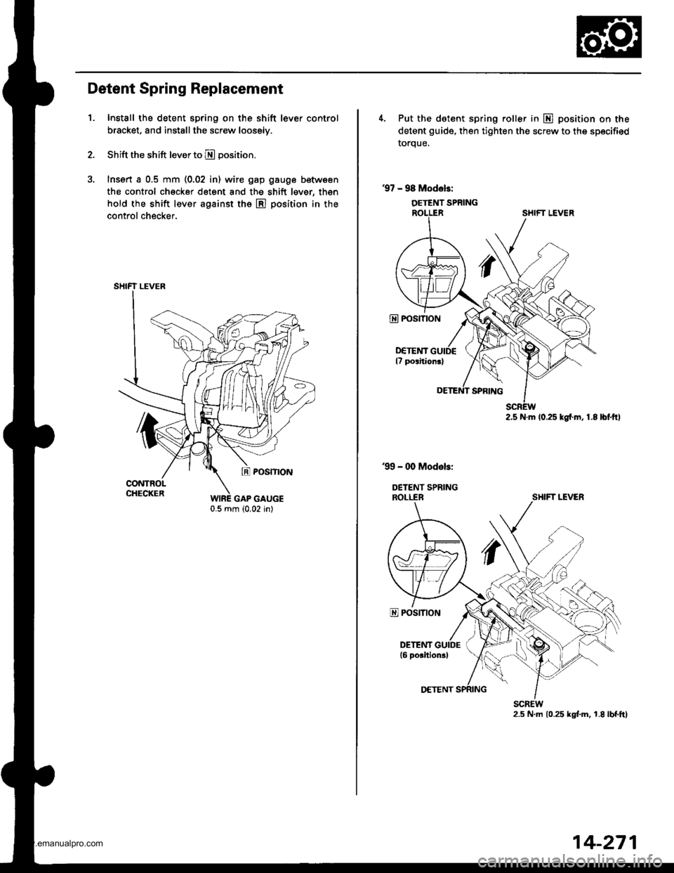
Detent Spring Replacement
1.Install the detent spring on th€ shift lever control
bracket, and installthe screw loosely.
Shift the shift lever to E position.
lnssrt a 0.5 mm (0.02 in) wire gap gauge between
the control chocker detent and the shift lever, then
hold the shift lever against the El position in the
control checker.
SHIFI LEVER
GAP GAUGE
4. Put the detent spring roller in E position on the
detent guide, then tighten the screw to the specified
torque,
'97 - 98 Modeb:
DETENT SPRING
2.5 N.m 10.25 kgf.m, 1.8lbl.ftl
SCREW2.5 N.m 10.25 kgl.m, 1.8lbtftl
14-271
www.emanualpro.com