Rear HONDA CR-V 1998 RD1-RD3 / 1.G Manual PDF
[x] Cancel search | Manufacturer: HONDA, Model Year: 1998, Model line: CR-V, Model: HONDA CR-V 1998 RD1-RD3 / 1.GPages: 1395, PDF Size: 35.62 MB
Page 816 of 1395
Driveshafts
Special Tools .......... ........... 16-2
Driveshafts
Inspection ...................... l6-3
Front Driveshafts
Removal .... 16-3
Disassembly ................... 16-5
Reassembly .................... 16-g
Installation ..................... 16-17
Intermediate Shaft
Removal .... 16-19
Disassembly ................... 16-19
Reassembly .................... 16-20
Installation ..................... 16-21
Rear Driveshafts
Removal .... 16-22
Disassembfy ................... 16-22
Reassembfy .................... 16-24
Installation ..................... 16-29
Propeller Shaft
Inspection . 16-29
RemovaUlnstallation .... 16-30
www.emanualpro.com
Page 837 of 1395
Rear Driveshafts
't.
Removal
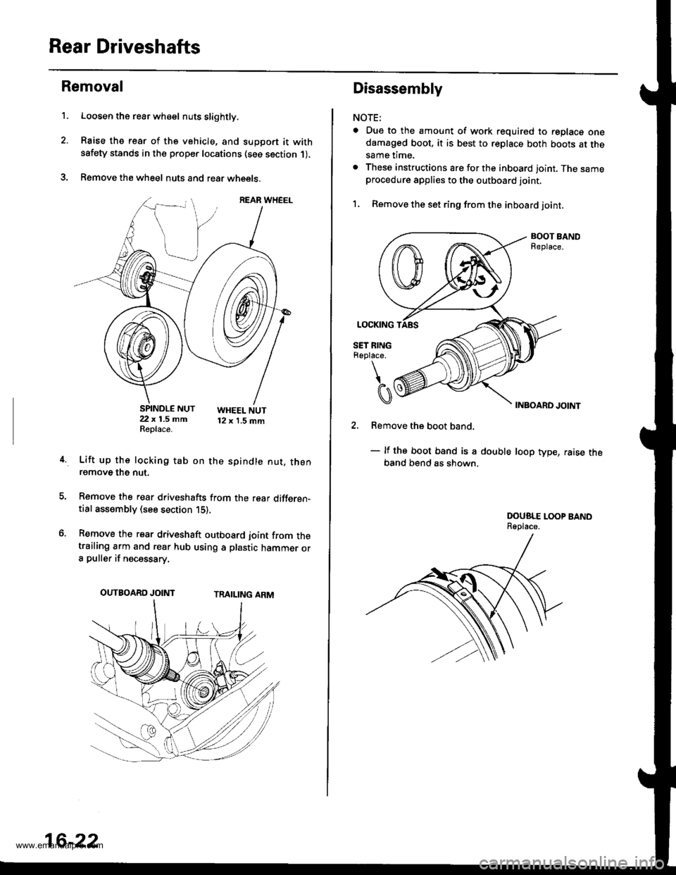
Loosen the rear wh€el nuts slightly.
Raise the rear of the vehicle, and support it withsafety stands in the proper locations (see section 1),
Remove the wheel nuts and rear wheets.
SPINDLE NUT22 x 1.5 mmReplace.
WHEEL NUT12 x 1.5 mm
4.Lift up the locking tab on the spindle nut. thenremove the nut.
Remove the rear driveshafts from the rear differen-tial assembly (see section 15),
Remove the rear driveshaft outboard joint from thetrailing arm and rear hub using a plastic hammer ora puller if necessary.
TRAILING ARMOUTBOARD JOINT
16-22
Disassembly
NOTE:
a Due to the amount of work required to replace onedamaged boot, it is best to replace both boots at thesame time.
. These instructions are for the inboard joint. The sameprocedure applies to the outboard joint.
1, Remove the set ring from the inboard joint,
BOOT BANDReplace.
INBOARD JOINT
2. Remove the boot band.
- lf the boot band is a double loop type, raise theband bend as shown,
DOUSLE LOOP BANDReplace.
www.emanualpro.com
Page 839 of 1395
Rear Driveshafts
CIRCLIP
Reassembly
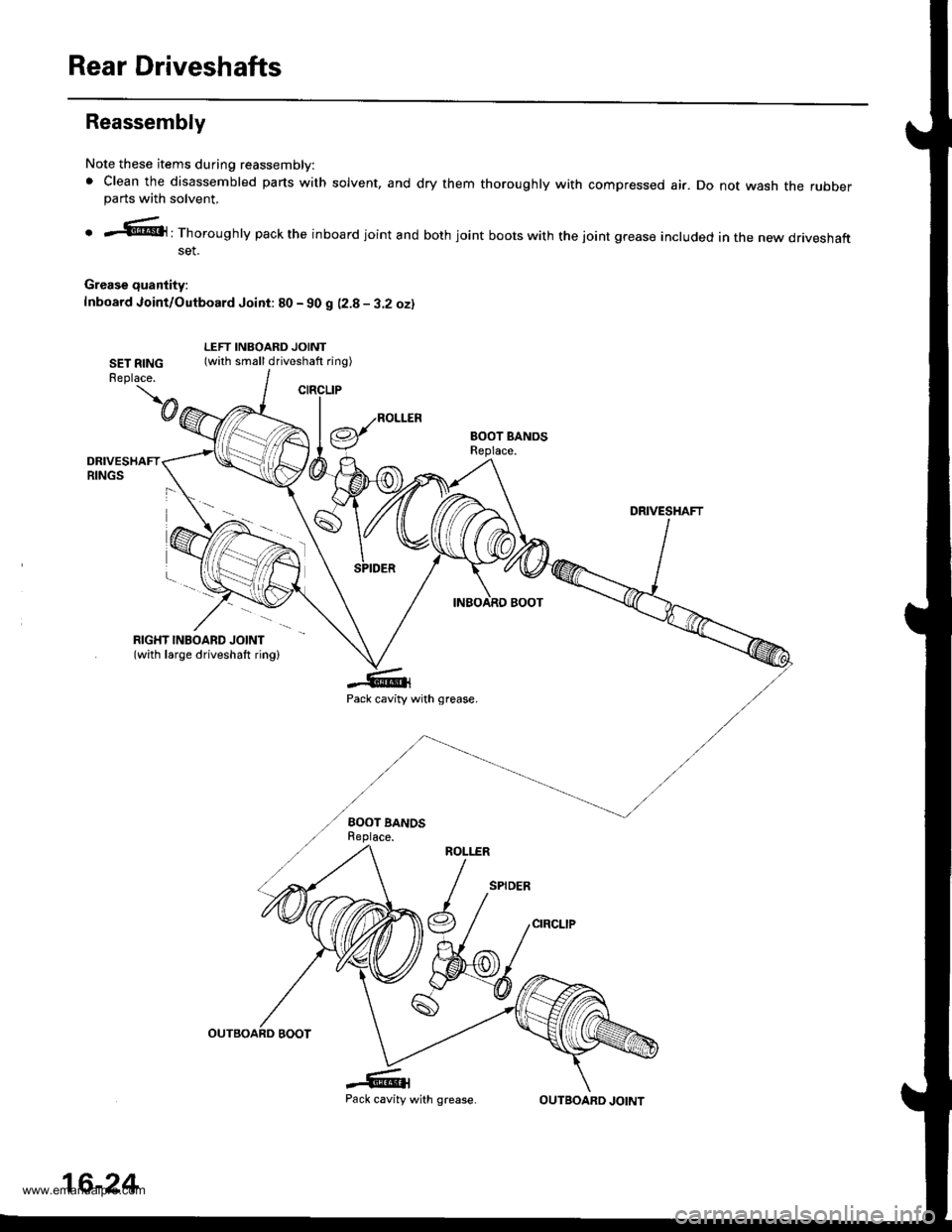
Note these items during reassembly:
. Clean the disassembled parts with solvent, and dry them thoroughly with compressed air. Do not wash the rubberparts with solvent,
o r''..@El: Thoroughly pack the inboard joint and both joint boots with the joint grease included in the new driveshaftset.
Grease quantity:
f nboard Joint/Outboard Joint: 80 - 90 g 12.8 - 3.2 ozl
SET RINGReplace.
LEFT INBOARD JOINT(with small driveshaft ring)
BOOT BANOSBeplace.
DRIVESHAFT
RIGHT INBOARD JOINT(with large driveshaft ring)
Pack cavity with grease.
BOOT BANOSReplace.
.6{Pack cavity
\@
DRIVESHAFTRINGS
ROLI.ER
16-24
with grease.OUTBOARD JOINT
www.emanualpro.com
Page 841 of 1395
Rear Driveshafts
Reassembly (cont'd)
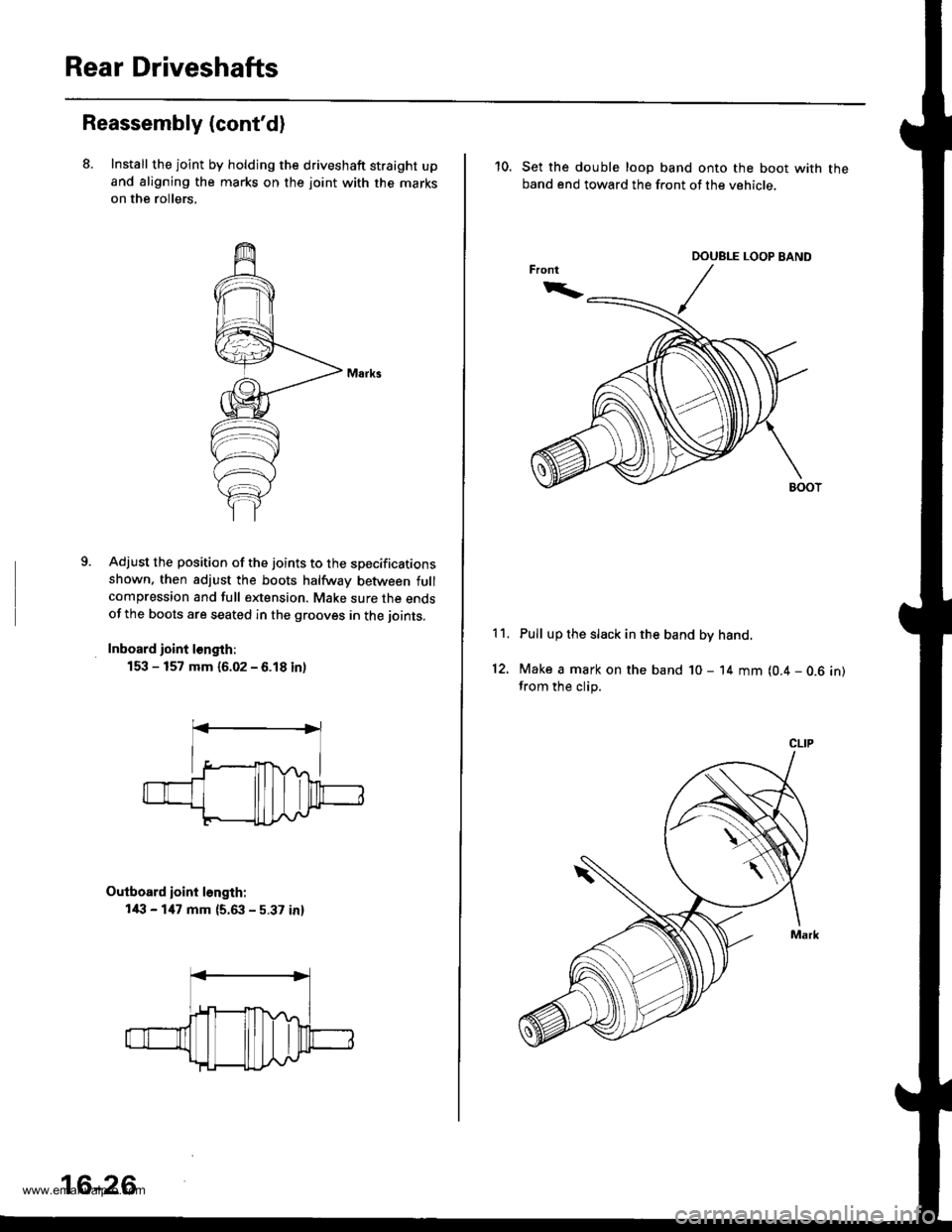
8. Install the joint by holdjng the driveshaft straight upand aligning the marks on the joint with the marks
on the rollers,
9.Adjust the position of the joints to the specificationsshown. then adjust the boots halfway between fullcompression and full extension. Make sure the endsof the boots are seated in the grooves in the joints.
Inboard ioint l€ngth:
153 - 157 mm {6.02 - 6.18 inl
Outboard ioint l6ngth:
l/l:' - 147 mm {5.63 - 5.37 in}
16-26
10. Set the double loop band onto the boot with theband end toward the front of the vehicle,
Pull up the slack in the band by hand.
Make a mark on the band 10 - 14 mm (0.4 - 0.6 in)from the clip.
11.
12.
CLIP
www.emanualpro.com
Page 843 of 1395
Rear Driveshafts
Reassembly (cont'd)
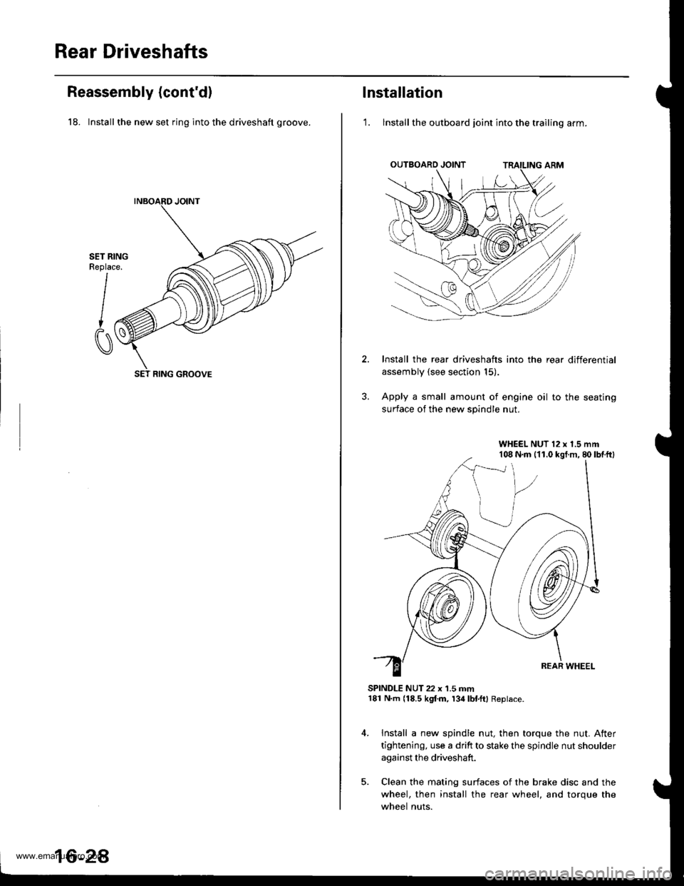
18. Install the new set ring into the driveshaft groove.
SET RINGReplace.
I
CI
SET RING GROOVE
16-2A
lnstallation
'1. lnstall the outboard joint into the trailing arm.
Install the rear driveshafts into the rear differential
assembly (see section 15).
Apply a small amount of engine oil to the seating
surface of the new spindle nut.
SPINDLE NUT 22 x 1.5 mm181 N.m (18.5 kgf.m, 134lbl.ftl Replace.
Install a new spindle nut, then torque the nut. After
tightening, use a drift to stake the spindle nut shoulder
against the driveshaft.
Clean the mating surfaces of the brake disc and the
wheel, then install the rear wheel, and torque the
wheel nuts.
WHEEL NUT 12 x 1.5 mm108 N.m (11.0 kgt.m, 80lbtftl
www.emanualpro.com
Page 845 of 1395
Propeller Shaft
RemovaUlnstallation
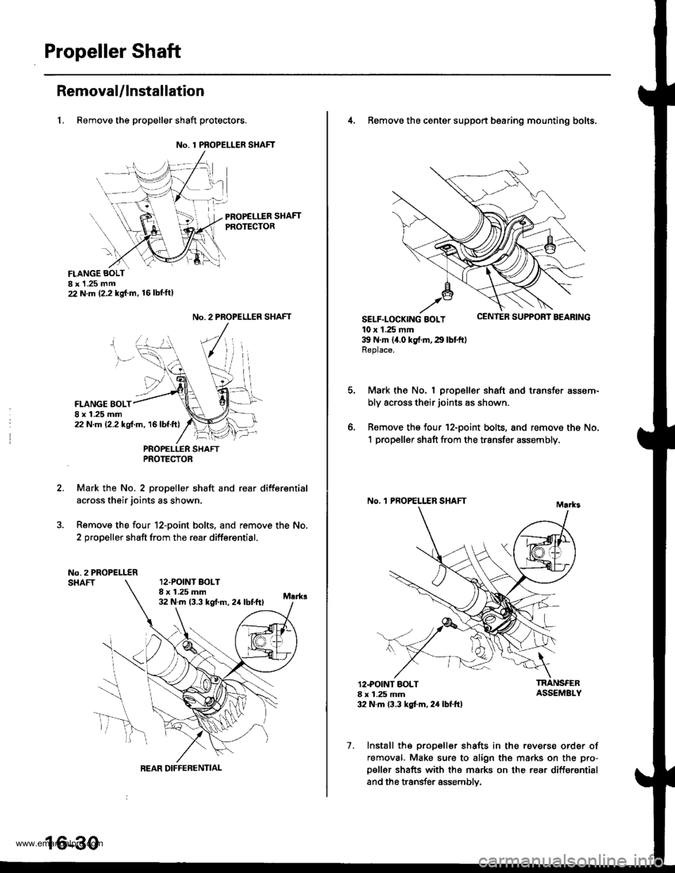
1, Remove the propeller shaft protectors.
No. 1 PROPELLER SHAFT
PROPELLER SHAFTPROTECTOR
FLANGE BOLTI x 1 .25 mm22 N.m (2.2 kg{.m. 16lbl'ft)
2.
No. 2 PROPELLER SHAFT
FLANGE BOLT8 x 1.25 mm22 N.m 12.2 kgf.m, 16lbf.ft)
PNOPELLER SHAFTPROTECTOR
Mark the No. 2 propeller shaft and rear differsntial
across their joints as shown.
Remove the four 12-point bolts. and remove the No.
2 propeller shaft from the rear differential.
No.2 PROPELLERSHAFT12.POINT BOLT8 x 1.25 mm32 N.m 13.3 kst m, 24 lbtftl
REAR DIFFERENTIAL
16-30
4, Remove the center support bearing mounting bolts.
SELF-LOCK|NG BOLT uErr rEn Durrr.r'r I I'EAnrNu
10 x 1.25 mm39 N'm 14.0 kg{.rn,29 lbtftlReplace.
Mark the No. I propeller shaft and transfer assem-
bly across their joints as shown.
Remove the four 12-point bolts, and remove the No.
1 propeller shaft from the transfer assembly,
No. 'l PROPELLER SHAFT
o.
12.POINT BOLT8 x 1.25 mm32 N.m 13.3 kgt'm, 2,1 lbf.ft)
TRANSFERASSEMBLY
7. Install the propeller shafts in the reverse order of
removal. Make sure to align the marks on the pro-
p€ller shafts with the marks on the rear differential
and the transfer assemblv.
www.emanualpro.com
Page 876 of 1395
Power Steering Gearbox
Removal
Note these items during removal:
. Using solvent and a brush, wash any oil and dirt off
the valve body unit its lines, and the end if the gear-
box. Blow dry with compressed air.
. Be sure to remove the steering wheel before discon-
necting the steering joint. Damage to the cable reel
can occur.
. With 4WD. tilt the engine with a jack to expand the
clearance between the transfer assembly and rear
beam when removing the steering gearbox from the
rear oeam.
Do not remove the steering gearbox by removing the
transfer assembly from the transmission.
1. Drain the power steering fluid as described on page'17-15.
Raise the vehicle, and suppon it on safety stands in
the proper locations (see section 1).
Remove the front wheels,
Remove the drive/s airbag assembly {see section 24).
Remove the steering wheel {see page 17-18).
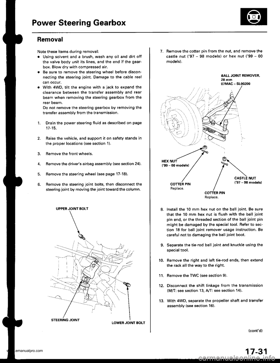
Remove the steering joint bolts, then disconnect the
steering joint by moving the joint toward the column.
UPPER JOINT BOLT
LOWER JOINT BOLT
13.
7. Remove the cotter pin from the nut, and remove the
castle nut {'97 - 98 models) or hex nut ('99 - 00
models).
COTTER PINReplace.
Install the 10 mm hex nut on the ball joint. Be sure
that the 10 mm hex nut is flush with the ball joint
pin end, or the threaded section of the ball joint pin
might be damaged by the special tool. Refer to sec-
tion 18 for ball joint remover usage instruction, Be
careful not to damaging the ball joint boot.
Separate the tie-rod ball joint and knuckle using the
special tool.
Remove the right and left tie-rod ends, then extend
the rack all the way to the right.
Remove the TWC (see section 9).
Disconnect the shift linkage from the transmission
(M/T: see section 13, A/T: see section 14).
With 4WD. separate the propeller shaft and transfer
assembly (see section 161.
10.
11.
(cont'd)
17-31
www.emanualpro.com
Page 878 of 1395
REAR MOUNT
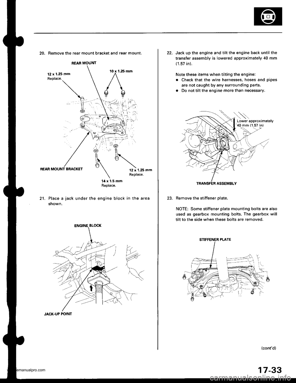
20. Remove the rear mount bracket and rear mount.
12 x 1.25 mmReplace.
REAR MOUNT BRACKET12 x 1.25 mmReplace.
21.
14 x 1.5 mmReplaco.
Place a jack under the engine block in the area
shown,
?*
JACK.UP POINT
17-33
22. Jack up the engine and tilt the engine back until the
transfer assembly is lowered approximately 40 mm
(1.57 in).
Note these items when tilting the engine:
. Check that the wire harnesses, hoses and pipes
are not caught by any surrounding parts.
. Do not tilt the engine more than necessary.
ASSEMBLY
Remove the stiffener olate.
NOTE: Some stiffener plate mounting bolts a.e also
used as gearbox mounting bolts. The gearbox will
tilt to the side when these bolts are removed.
(cont'd)
.Lower approximately'40 mm (1.57 in)
STIFFENER PLATE
www.emanualpro.com
Page 879 of 1395
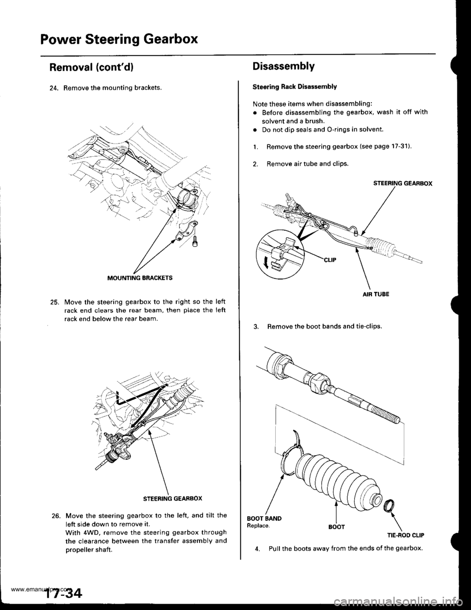
Power Steering Gearbox
Removal (cont'dl
24. Remove the mounting brackets.
25.lvlove the steering gearbox to the right so the
rack end clears the rear beam, then place the
rack end below the rear beam.
left
left
Move the steering gearbox to the left, and tilt the
left side down to remove it.
With 4WD. remove the steering gearbox through
the clearance between the transfer assembly and
propeller shaft.
MOUNTING BRACKETS
STEEBING GEARBOX
17 -34
4. Pull the boots away from the ends of the gearbox.
Disassembly
Steering Rack Disassembly
Note these items when disassembling:
. Before disassembling the gearbox, wash it off with
solvent and a brush.
. Do not dip seals and O-rings in solvent.
1. Remove the steering gearbox (see page 17-31).
2. Remove airtube and clips.
3. Remove the boot bands and tie-clips.
AIR TUBE
www.emanualpro.com
Page 896 of 1395
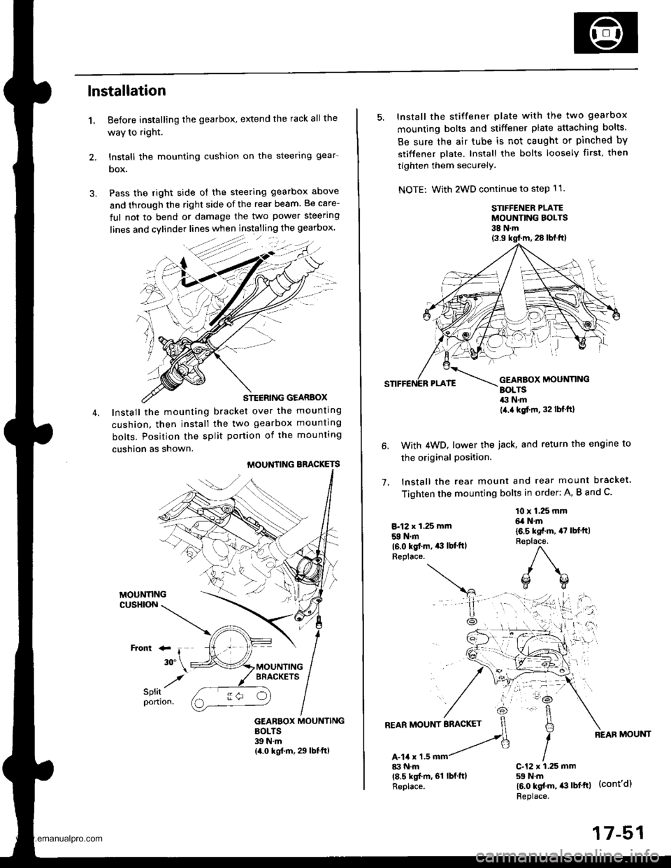
lnstallation
1. Before installing the gearbox, extend the rack all the
waY to right.
2. lnstall the mounting cushion on the steerlng gear-
box.
3. Pass the right side of the steering gearbox above
and through the right side of the rear beam. Be care-
ful not to bend or damage the two power steering
STEERING GEARBOX
Install the mounting bracket over the mounting
cushion. then install the two gearbox mounting
bolts. Position the split portion of the mounting
cushion as shown.
MOUNTING BBACKETS
GEARBOX MOUNTINGBOLTS39 N.m14.0 kgf.m, 29 lbf.ft)
:-
/
5. Install the stiffener plate with the two gearbox
mounting bolts and stiffener plate attaching bolts.
Be sure the air tube is not caught or pinched by
stiffener plate. Install the bolts loosely first. then
tighten them securely.
NOTE: With 2WD continue to step 11.
STIFFENER PLATEMOUNTING BOLTS38 N.m
1.
With 4WD, lower the iack, and return the engine to
the original Position.
lnstall the rear mount and rear mount bracket.
Tighten the mounting bolts in order: A, B and C.
8.12 x 1,25 mm
59 N.m(6.0 kgt.m. *l lb{'ftlReplace.
10 x 1.25 mm6,a N.m
16.5 kst.m, 47 lbl'ft)R€place.
)\^
o(]
17-51
www.emanualpro.com