Rear HONDA CR-V 1998 RD1-RD3 / 1.G Owners Manual
[x] Cancel search | Manufacturer: HONDA, Model Year: 1998, Model line: CR-V, Model: HONDA CR-V 1998 RD1-RD3 / 1.GPages: 1395, PDF Size: 35.62 MB
Page 921 of 1395
Rear Damper
1.
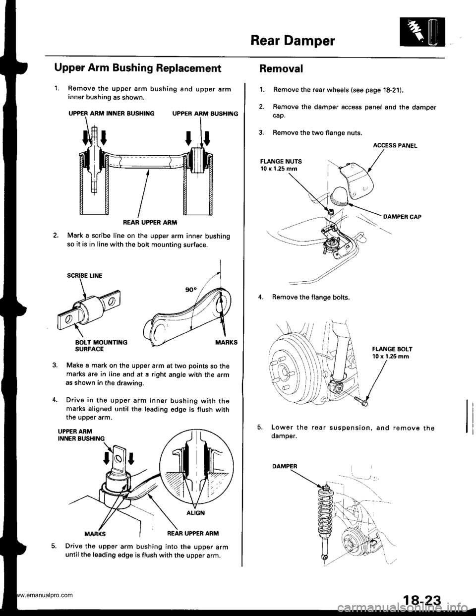
Upper Arm Bushing Replacement
Remove the upper arm bushing and upper arminner bushing as shown.
UPPER ARM INNER BUSHING UPPER ARM AUSHIT{G
Mark a scribe line on the upper arm inner bushing
so it is in line with the bolt mounting surface.
BOLT MOUNTII{GSURFACE
Make a mark on the upper arm at two points so the
marks are in line and at a right angle with the arm
as shown in the drawing.
Drive in the upper arm inner bushing with themarks aligned until the leading edge is flush with
the uoDer arm.
Drive the upper arm bushing into the upper armuntil the leading edge is flush with the upper arm.
REAR UPPER ARM
5.
Removal
Remove the rear wheels (see page '18-21),
Remove the damper access panel and the damper
cap.
Remove the two flange nuts.
ACCESS PANEL
OAMPER CAP
't.
4. Remove the flange bolts.
Lower the rear suspension, and remove
damper.the
1a-23
www.emanualpro.com
Page 922 of 1395
Rear Damper
Disassembly/lnspection
Disassembly
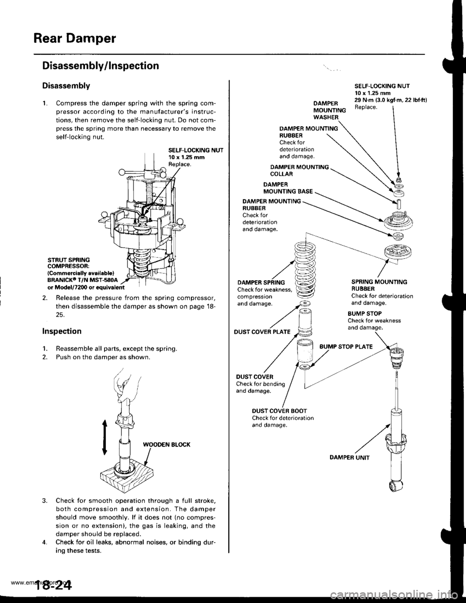
L Compress the damper spring with the spring com-
pressor according to the manufacturer's instruc-
tions, then remove the self-locking nut. Do not com-
press the spring more than necessary to remove the
self-locking nut.
SELF-LOCKING NUT10 x 1.25 mmReplace.
STRUT SPRINGCOMPRESSOR:lCommercirlly avaihblo)BRANICKO I/N MSI-580Aor Mod6l/7200 or equivalent
2. Release the pressure from the spring compressor,
then disassemble the damper as shown on page 18-
25.
Inspection
1. Reassemble all parts, except the spring.
2. Push on the damper as shown.
3.
WOODEN ELOCK
Check for smooth operation through a full stroke,
both compression and extension. The damper
should move smoothly. lf it does not (no compres-
sion or no extension), the gas is leaking, and the
damper should be replaced.
Check for oil leaks, abnormal noises, or binding dur-
ino these tests.
4.
SELF-LOCKING NUT10 x 1.25 mm
OAMPERMOUNTINGWASHER
29 N.m {3.0 kgf.m, 22 lbf.ft)Beplace.
OAMPER MOUNTINGRUBBERCheck fordeteriorationano oamage.
DAMPER MOUNTINGCOLLAR
DAMPERMOUNTING BASE
DAMPER MOUNTINGRUBBERCheck fordeteriorationano oamage.
'"dd"^.s"'
//F,
DAMPERCheck for weakness,compressron
DUST COVER PLATE
DUST COVERCheck for bendingand damage.
SPRING MOUNTINGRUBBERCheck Ior deteriorationand damage.
BUMP STOPCheck for weaknessano oamage.
DUST COVEN BOOTCheck for deterioralionano oamage.
BUMP STOP PLATE
DAMPER
www.emanualpro.com
Page 923 of 1395
Reassembly
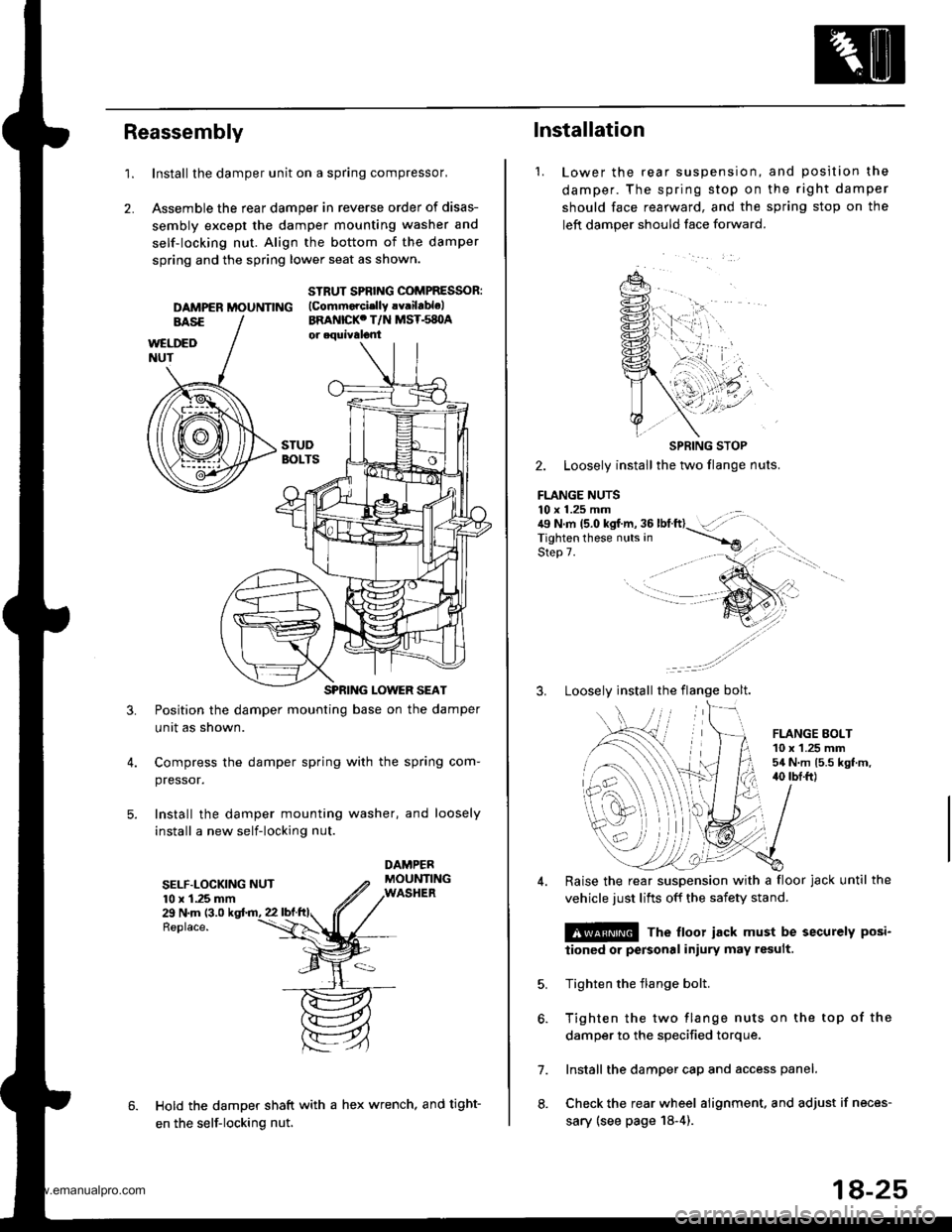
1.Install the damper unit on a spring compressor,
Assemble the rear damper in reverse order of disas-
sembly except the damper mounting washer and
self-locking nut. Align the bottom of the damper
spring and the spring lower seat as shown.
2.
DAMPER MOUNNNG
STRUT SPBING COMPRESSOR:(Commorcislly !v.ilablelBRANICKC T/N MST.s8OA
3.Position the damper mounting base on the damper
unit as shown.
Compress the damper spring with the spring com-
pressor.
Install the damper mounting washer, and loosely
install a new self-locking nut.
SELF.LOCKING NUT10 x 1.25 mm29 N.m (3.0
Replace.
Hold the damper shaft with a hex wrench, and tight-
en the self-locking nut.
1.
lnstallation
Lower the rear suspenston,
damper. The spring stop on
should face rearward, and the
left damper should face forward.
and position the
the right damper
sprang stop on the
SPRING STOP
2. Loosely install the two flange nuts.
FLANGE NUTS10 x 1.25 mm . .:{9 N.m 15.0 kgf.m, 36 lbtft}- :',,-rigf't"n if'"""_nrr. in ----.-*
qla^ 7Step 7.
3. Loosely install the flange bolt.
FLANGE EOLT10 x 1.25 mm54 N.m 15.5 kgt.m,40 tbI.ft)
6.
7.
8.
Raise the rear suspension with a floor jack until the
vehicle just lifts off the safety stand.
@ The floor iack must be securely posi-
iioned or personal iniury may result.
Tighten the flange bolt.
Tighten the two flange nuts on the top of the
damper to the specified torque.
Install the damper cap and access panel.
Check the rear wheel alignment. and adjust if neces-
sary (see page 18-4).
18-25
www.emanualpro.com
Page 925 of 1395
Brakes
Special Tools ............. 19-2
Component Locations
lndex ................ ...... 19-3
Inspection and Adlustment
Brake System Rubber Parts
and Brake Booster ..........,,,.......... 19-4
Brake Pedal ............ 19-5
Parking Brake ........ 19-6
Bleeding ................. 19'7
Brake System Indicator ................... 19-8
Front Brake Pads
Inspection and Replacement .......... 19-9
Front Brake Disc
Disc Runout Inspection ................... 19-11
Disc Thickness and
Parallelism Inspection ........,........ 19-1 1
Front Brake Caliper
Disassembly/Reassembly ............... 19-12
Master Cylinder/Brake Booster
Removal/lnstallation ....................... 19-13
Master Cylinder
Inspection/Disassembly .............. 19-14
Pushrod Clearance Adiustment ...... 19-14
Brake Booster Inspection ...,.,,,,....... 1 9-1 5
Rear Drum Brakes
Inspection .............. 19-15
Brake Shoes
Replacement ..... 19-r 8
Wheel Cylinder Replacement ......... 19-20
Brake Hoses/Lines
Inspection/Torque Specifications ... 19-21
Hose Replacement ....,...,............. ..,,, 19-22
Parking Brake Cable
Inspection and Replacement .......... 19-23
www.emanualpro.com
Page 927 of 1395
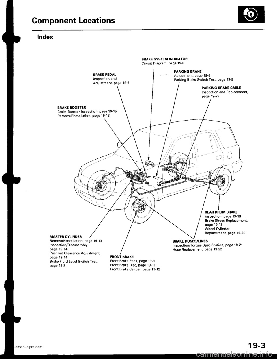
Gomponent Locations
lndex
ERAKE SYSTEM INOICATORCircuit Diagram, page't9-8
PARKING BRAKEAdjustment, page 19-6Parking Brake Switch Test, page '19-8
PARKING BRAKE CABI..EInspection and Replacement,page 19-23
BRAKE BOOSTERBrake Booster Inspection, page 19-15
Removal/lnstallation, page 19 13
MASTER CYLINDER
Inspection, pago 19-16Brake Shoes Replacement,page 19-18Wheel CylinderReplacement, page 19-20
REAR DRUM BRAKE
Removal/lnstallation, page 19-13lnspection/Disassembly.page 19-14Pushrod Clearance Adjustment,page 19 ldBrake Fluid LevelSwitch Test,page 19-8
Inspection/Torque Specification, pag€'19-21
Hose Replacement, Page 19-22
Front Brake Pads, page 19-9Front Brake Disc. page 19-11Front Brake Caliper, page 19-12
)i't ' -"''
/'"''t,'..,1 ...,. , \,,,.
i ,.'
'a.,
I
.) ..)
t ^fl)
19-3
www.emanualpro.com
Page 930 of 1395
Inspection and Adjustment
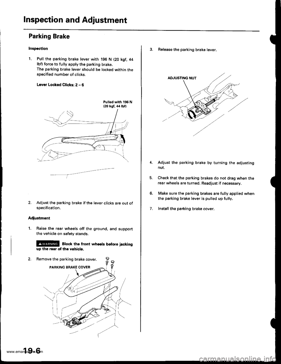
Parking Brake
Inspeqtion
1. Pull the parking brake lever with
lbfl force to fully apply the parking
The parking brake lever should be
specified number of clicks.
L.var Lockod Clicks: 2 - 6
196 N (20 kqf, 44
brake.
locked within the
2. Adjust the parking brake if the lever clicks are out ofspecification.
Adiustment
1. Raise the rear wheels off the ground. and support
the vehicle on safety stands.
@@ Bbck tho front who€ts betore iackingup the rear ot tho vohicle.
2. Remove the parking brake cover
PARKING BRAKE COVER
19-6
3. Release the parking brake lever.
Adjust the parking brake by turning the adjusting
nut.
Check that the parking brakes do not drag when therear wheels are turned. Readjust if necessary.
Make sure the parking brakes are fully applied when
the parking brake lever is pulled up fully.
Installthe parking brake cover.7.
www.emanualpro.com
Page 931 of 1395
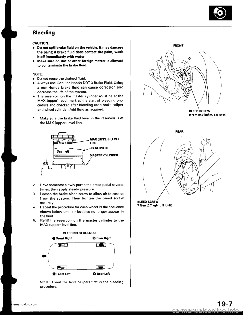
Bleeding
CAUNON:
. Do not spill brake tluid on the vehicle. it may damage
the paint; if brake fluid does contaqt th€ paint, wash
it otf immodiately with water.
. Maks sure no dirt oy other forsign matter is allowsd
to contaminate the brake fluid.
NOTE:
. Do not reuse the drained fluid.
. Always use Genuine Honda DOT 3 Brake Fluid. Using
a non-Honda brake fluid can cause corrosion and
decrease the life of the svstem.
. The reservoir on the master cylinder must be at the
MAX (upper) level mark at the start of bleeding pro-
cedure and checked after bleeding each brake caliper
and wheel cylinder. Add fluid as required.
1, Make sure the brake fluid level in the reservoir is at
the MAX (uDDer) level line.
MAX {UPPER) LEVELLINE
RESERVOIR
MASTER CYLINDER
2.
3.
Have someone slowly pump the brake pedal several
times, then apply steady pressu.e.
Loosen the brake bleed screw to allow air to escape
from the system. Then tighten the bleed screw
securely.
Repeat the procedure for each wheel in the sequence
shown below until air bubbles no longer appear in
the tluid.
Refill the reservoir on the master cvlinder to the
MAX (upper) level line.
ALEEDING SEOUENCE:
O Front RightGt Rear Right
O Front LeflO Rear Left
NOTE: Bleed the front calipers first in the bleeding
procedure.
4.
FRONT:
BLEEO SCREW7 N.m (0.? kgf.m, 5 lbf.ftl
19-7
www.emanualpro.com
Page 937 of 1395

Master Cylinder/Brake Booster
Removal/lnstallation
1, Disconnect the brake fluid level switch connectors.
2. Remove the reservoir cap from the master cylinder.
3. Remove the brake fluid from the master cvlinder
reservoir with a syringe.
4. Disconnect the brake lines from the master cylinder.
To prevent spills, cover the line joints with rags or
shop towels.
5. Remove the master cylinder mounting nuts and
wasners.
6. Remove the master cylinder from the brake booster.
CAUTION: Be careful not to bend or damage the
brake lines when removing the master cylinder.
Do not spill brake fluid on the vehicle; it may dam.
age the paint; it brake fluid does cont.ct the paint,
wash it oft immediately with water.
7. Disconnect the vacuum hose from the brake booster.
8. Remove the cotter pin and clevis pin from the clevis.
Do not disconnect the clevis by removing it from
the operating rod of the brake booster. lf the clevis
is loosened, adjust the pushrod length before
installing the brake booster (see page 19-15).
To Front Caliper (Without ABS)
\\
15 N.m {1.5 kgtm, vAcuuM HosE
r r rbf.ft) |
/ | BRAKE FLUTD LEvEL
/l /
swrrcHcoNNEcroRs
/ I I I COTTER PIN
I I / neotace
l,/-- ro Rear wheet cylinders / | I
h ./-''' /. I I IYli //*s (.S
I /r:
9. Remove the four booster mounting nuts.'10. Pull the brake booster forward until the clevis is
clear of the bulkhead.
11. Remove the brake booster from the enqine com-
panment.
12. Install the brake booster and master cylinder in the
reverse order of removal, and note these items:
. When connecting the brake lines, make sure that
there is no interference between the brake lines
and other parts.
. Be careful not to bend or damage the brake lines
when installing the master cylinder.
. lf replacing the master cylinder or brake booster,
check and adjust the pushrod clearance before
installing the master cylinder (see page 19-14).
Fill the master cylinder reservoir, and bleed the
brake system (see page 19-7).
After installation, check the brake pedal height and
brake pedal free play (see page 19-5), and adjust if
necessary.
13 N.m 11.3 kg{.m,I rbf.ft)
13.
14.
To Master Cylinder(Without ABS)To Modulator Unit(with ABs)@-\
\
^ To Front Caliper
9i\.
-#qCLEVIS PIN
):-,/
PROPORTIONING CONTROL VALVE
MASTER CYLINDER
15 N.m (1.5 kgf.m, 11 lbl.ftl
BRAXE BOOSTER
www.emanualpro.com
Page 940 of 1395
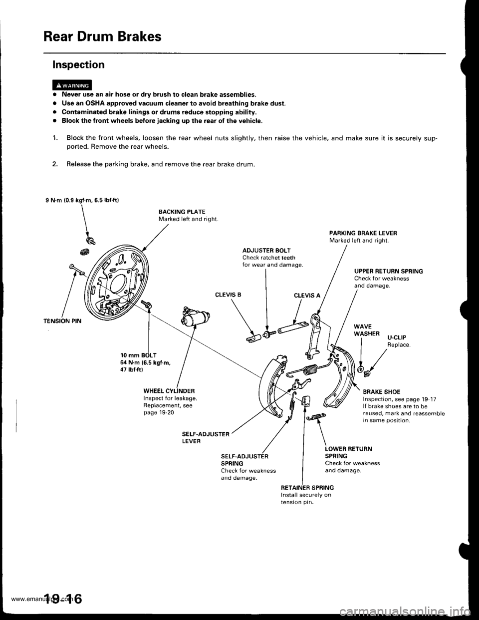
Rear Drum Brakes
Never use an air hose or dry brush to clgan brake assemblies,
Use an OSHA approved vacuum cleaner to avoid breathing brake dust.
Contaminated brake linings or drums reduce stopping ability.
Block the front wheels betore iacking up lhe rear ot the vehicle,
Block the front wheels, loosen the rear wheel nuts slightly, then raise the
poned. Remove the rear wheels.
2. Release the parking brake, and remove the rear brake drum.
I N.m {0.9rbr.ft)kgl.m,5.5
\\
\
196
@
Inspection
a
a
rl
a
1.vehicle, and make sure it is securely sup-
BACKING PLATEMarked left and right.
PARKING EBAKE I-EVERMarked left and right.
ADJUSTER BOLTCheck ratchet teethfor wear and damage.UPPER RETURN SPRINGCheck for weaknessand damage.
CLEVIS BCLEVIS A
64 N.m 16.5 kgl.m,47 lbt.ftl
\L;
SPRINGCheck for weaknessano oamage.
'l-'-' u-cllP
I Replace.
t/
6d/
BRAKE SHOEInspection, see page 19 17lf brake shoes are to bereused, mark and reassemblein same position.
WHEELInspect for leakage.Replacement, seepage 19-20
LOWER RETURNSPRINGCheck for weaknessano oamage.
RETAINER SPRINGInstall securely onlensron prn.
19-16
www.emanualpro.com
Page 942 of 1395
Rear Drum Brakes
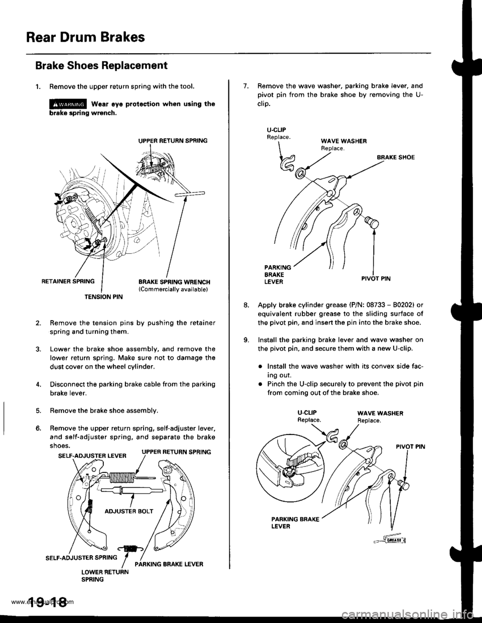
Brake Shoes Replacement
1. Remove the upper return spring with the tool.
l@ w€ar eye protestion when using the
brske spring wrench.
RETAINER SPRINGBRAKE SPRING WBENCH{Commerciallv available)
Remove the tension pins by pushing the retainer
spring and turning them.
Lower the brake shoe assembly, and remove the
lower return spring, Make sure not to damage the
dust cover on the wheel cylinder,
Disconnect the parking brake cable from the parking
brake lever.
Remove the brake shoe assembly,
Remove the upper return spring, self-adjuster lever,
and self-adjuster spring, and separate the brake
shoes.
TENSION PIN
5.
o.
SELF.ADJUSTER LEVER UPPER RETURN SPRING
19-18
7. Remove the wave washer, parking brake lever. and
pivot pin from the brake shoe by removing the U-
cliD.
BRAKE SHOE
Apply brake cylinder grease (P/N: 08733 - 80202) or
equivalent rubber grease to the sliding surface of
the pivot pin, 8nd insert the pin into the brake shoe.
Install the parking brake lever and wave washer on
the pivot pin, and secure them with a new U-clip.
. lnstall the wave washer with its convex side fac-
Ing our.
. Pinch the U-clip securely to prevent the pivot pin
from coming out of the brake shoe.
U.CLIPReplace.
\\
w
U-CLIPReplace.WAVE WASHERReplace.
www.emanualpro.com