clutch HONDA CR-V 1998 RD1-RD3 / 1.G Manual PDF
[x] Cancel search | Manufacturer: HONDA, Model Year: 1998, Model line: CR-V, Model: HONDA CR-V 1998 RD1-RD3 / 1.GPages: 1395, PDF Size: 35.62 MB
Page 527 of 1395
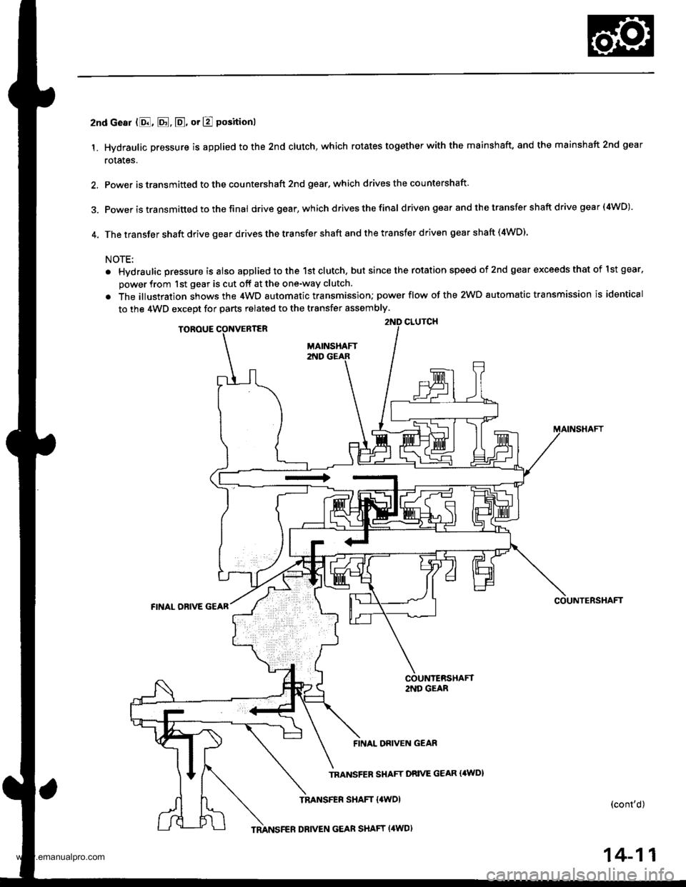
2nd cesr (8, E. E, or E positionl
1. Hydraulic pressure is applied to the 2nd clutch, which rotates together with the mainshaft, and the mainshaft 2nd gear
rotales.
2. Power is transmitted to the countershaft 2nd gear, which drives the countershaft
3. power is transmitted to the final drive gear, which drivesthefinal d riven gear and the transfer shaft drive gea r (4WD)
4. The transfer shaft drive gear drives the transfer shaft and the transfer driven gear shaft (4WD).
NOTE:
. Hvdraulic pressure is also applied to the 1st clutch, but since the rotation speed of 2nd gear exceeds that of lst gear.
power from 1st gear is cut off at the one-way clutch.
. The illustration shows the 4WD automatic transmission; power flow of the 2WD automatic transmission is identical
to the 4WD except for parts related to the transfer assembly.
CLUICHTOROUE
COUNTERSHAFTFINAL ORIVE GEAR
2NO GEAR
FINAL DRIVEN GEAF
TRANSFER SHAFT DBIVE GEAR {4WD}
TRANSFER SHAFT {4WDI(cont'd)
TMNSFER DRIVEN GEAR SHAFT (4WD)
14-11
www.emanualpro.com
Page 528 of 1395
Description
Power Flow (cont'd)
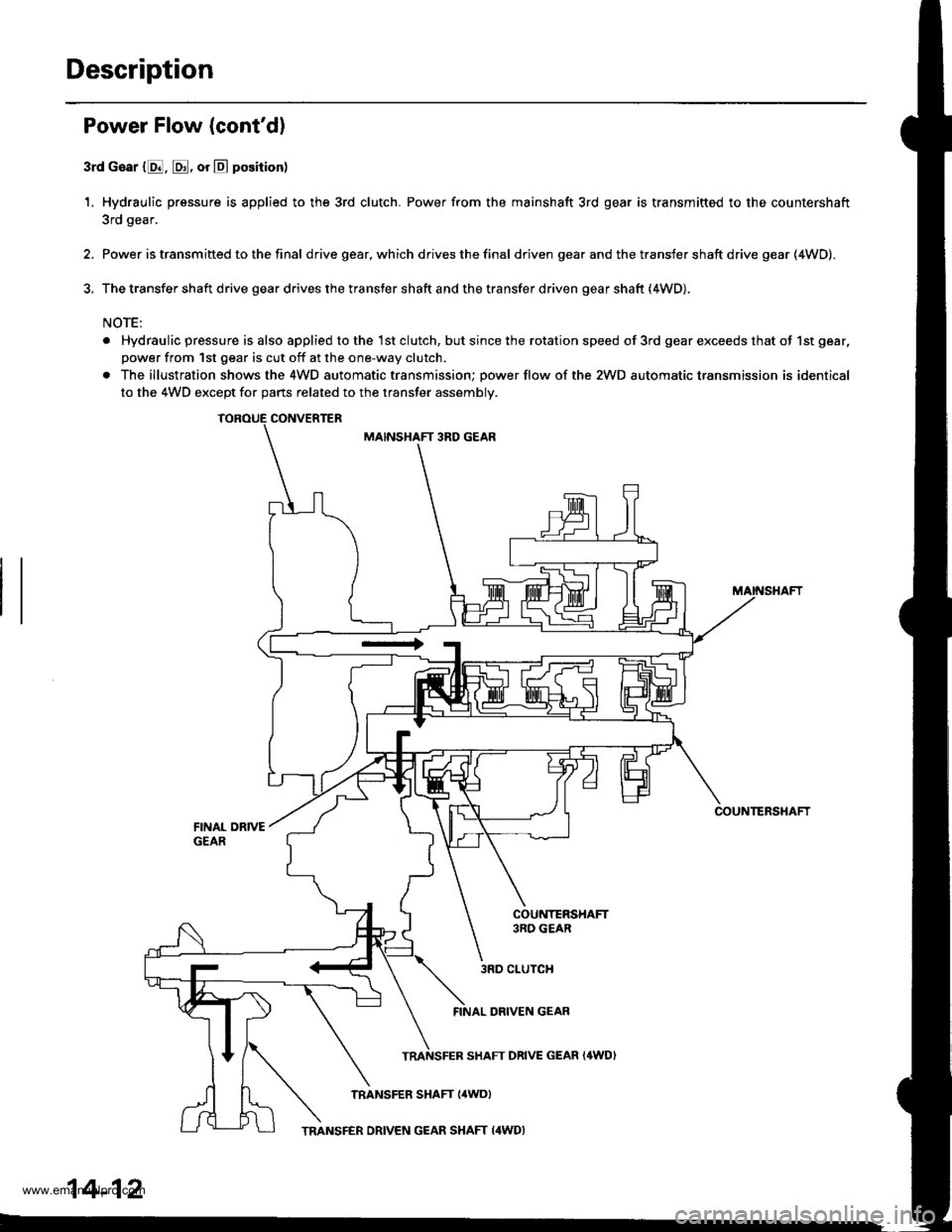
3rd Gear {8. @, or @ position)
1. Hydraulic pressure is applied to the 3rd clutch. Power from the mainshaft 3rd gear is transmitted to the countershaft
3rd gear.
2. Power is transm ifted to the final d rive gear, wh ich d rives the f inal driven gear and the transfer shaft drive gear (4WD).
3, The transfer shaft drive gear drives the transter shaft and the transfer driven gear shaft (4WD).
NOTE:
. Hydraulic pressure is also applied to the 1st clutch, but since the rotation speed of 3rd gear exceeds that of 1st gear,
power from lst gear is cut off at the one-way clutch.
. The illustration shows the 4WD automatic transmission; Dower flow of the 2WD automatic transmission is identical
to the 4WD except for parts related to the transfer assembly.
CONVERTEF
MAINSHAFT 3RD GEAR
COUNTERSHAFT
COUNTERSHAFT3RO GEAR
3RD CLUTCH
DRIVEN GEAR
SHAFT DRIVE GEAR (4WO)
TRANSFER SHAFT (,lwDl
TRANSFER ORIVEN GEAN SHAFT (4WD)
14-12
www.emanualpro.com
Page 529 of 1395
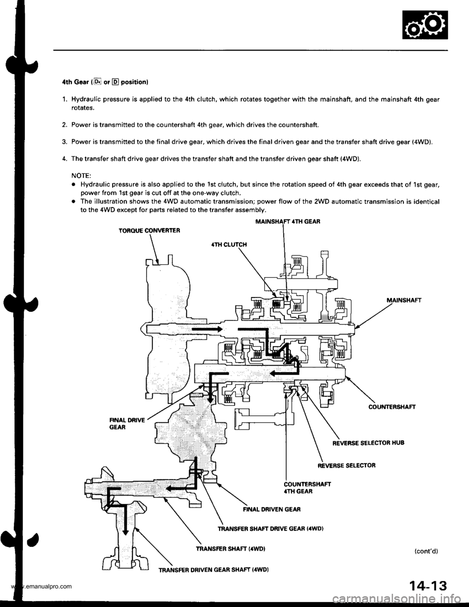
4th Goar (E or D positionl
1. Hydraulic pressure is applied to the 4th clutch, which rotates together with the mainshaft, and the mainshaft 4th gear
rotates,
2. Power is transmitted to the countershaft 4th gear, which drives the countershaft.
3. Power is transm ifted to the f inal d rive gear, which drives the fina I driven gear and the transfer shaft drive gear (4WD).
4. The transfer shaft drive gear drives the transfer shaft and the transfer driven gear shaft {4WD).
NOTE:
. Hydraulic pressure is also applied to the 1st clutch, but since the rotation speed of 4th gear exceeds that of 1st gear,
power from 1st gear is cut off at the one-way clutch,
. The illustration shows the 4WO automatic transmission; power flow of the 2WD automatic transmission is identical
to the 4WD except for parts related to the transfer assembly.
ilTH GEAR
TOROUE CONVERTER
.TH CLUTCH
COU'{TERSHAFT
REVERSE SELECTOR HUB
REVERSE SELECTOR
FINAL DRIVEN GEAR
TRANSFEB SHAFT DRIVE GEAB I'WD)
TNANSFER SHAFT I4WDI{cont'd)
14-13
TMNSFER DRIVEN GEAR SHAFT (4WDI
www.emanualpro.com
Page 530 of 1395
Description
Power Flow (cont'dl
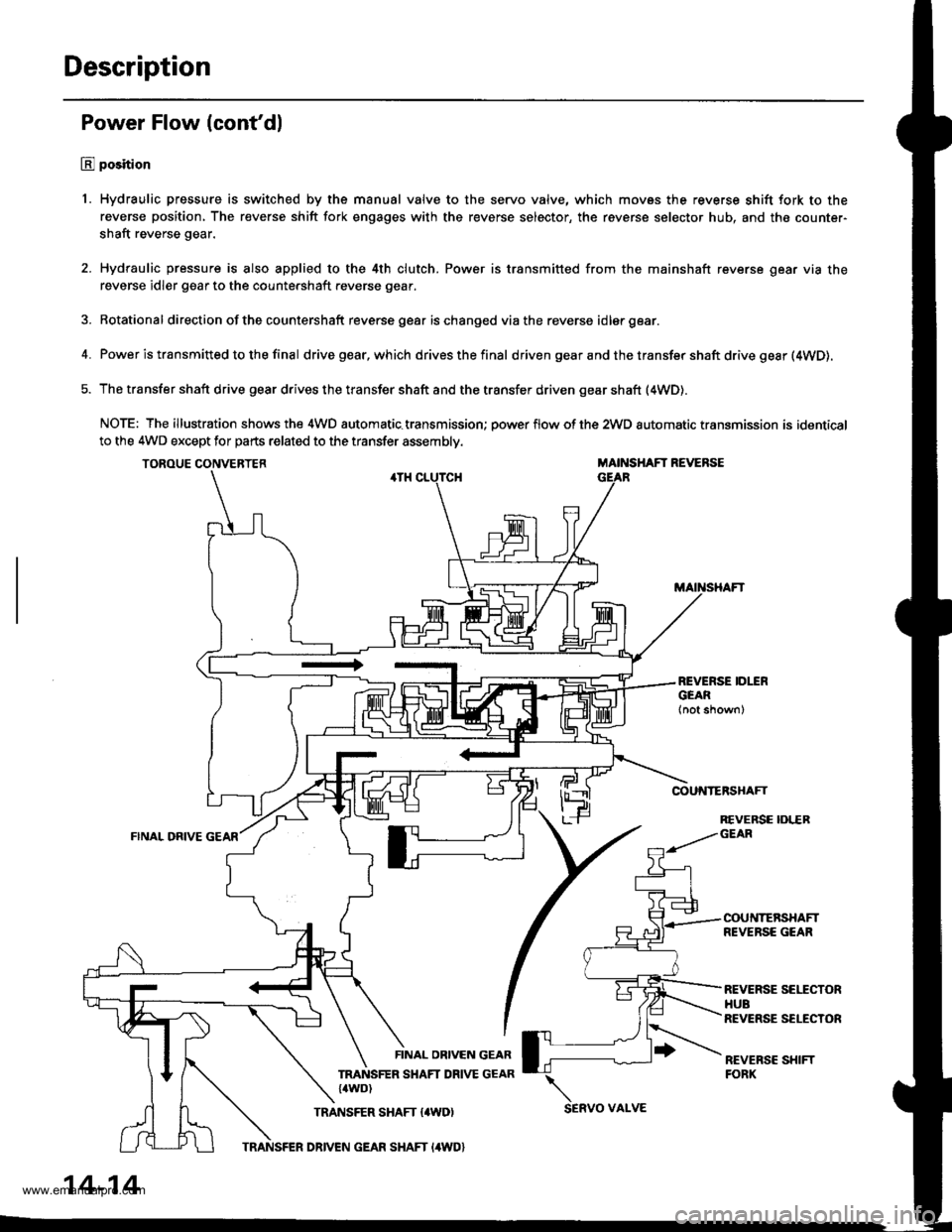
E position
1. Hydraulic pressure is switched by the manual valve to the servo valve, which movss the reverse shift fork to the
reverse position, The reverse shift fork engages with the reverse selector, the reverse selector hub, and the counter-
shaft reverse gear.
2. Hydraulic pressure is also applied to the 4th clutch. Power is transmitted from the mainshaft reverse gear via the
reverse idler gear to the countershaft reverse gear.
3. Rotational direction ofthe countershaft reverse gear ischanged viathe reverse idlergear.
4. Power is transmitted to the final drivegear,which drivesthefinal d riven gear a nd the transfer shaft drive gesr (4WD).
5. The transfer shaft drive gear drives the transfer shaft and the transfer driven gear shaft (4WD).
NOTE: The illustration shows the 4WD automatic.transmission; power flow of the 2wD automatic transmission is identical
to the 4WD except for parts related to the transfer assembly.
TOROUE CONVERTERMAINSHAFT REVERSE
COUNTERSHAFT
FINAL ORIVE
REVERSE IDLERGEAR
COUNTERSHAFTREVERSE GEAR
REVERSE SEITCTORHUBREVERSE SELECTOR
REVEBSC SHIFTFORK
FINAL OBIVEN GEAR
TRANSFER SHAFT DRIVE GEAR{4WD)
TRANSFER SHAFT {4WD)SERVO VAI-VE
14-14
TRANSFER DRIVEN GEAR SHAFT I4WD}
www.emanualpro.com
Page 540 of 1395
Description
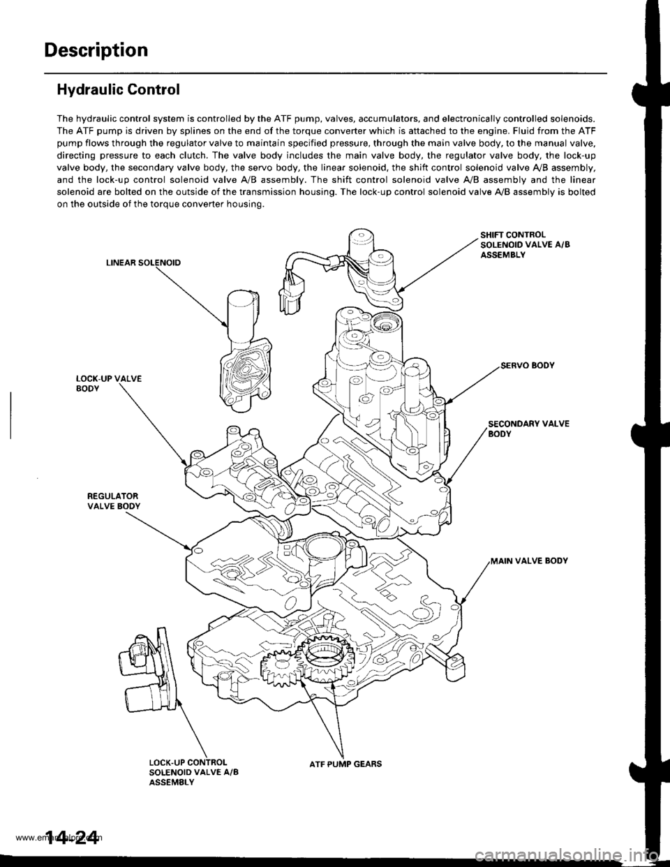
Hydraulic Control
The hydraulic control system is controlled by the ATF pump, valves, accumulators, and electronically controlled solenoids.
The ATF pump is driven by splines on the end of the torque converter which is aftached to the engine. Fluid from the ATF
pump flows through the regulator valve to maintain specified pressure, through the main valve body, to the manual valve,
directing pressure to each clutch. The valve body includes the main valve body, the regulator valve body, the lock-up
valve body, the secondary valve body, the servo body, the linear solenoid, the shift control solenoid valve Ay'B assembly,
and the lock-up control solenoid valve A/B assembly. The shift control solenoid valve A,/B assembly and the linear
solenoid are bolted on the outside of the transmission housing. The lock-up control solenoid valve A,/B assembly is bolted
on the outside of the torque converter housing.
LINEAR
SHIFT CONTROLSOLENOID VALVE A/BASSEMBLY
SECONDARY VALVEBODY
REGULATORVALVE BOOY
VALVE BODY
SOLENOID VALVE A/BASSEMELY
N
ATF PUMP GEARS
14-24
www.emanualpro.com
Page 545 of 1395
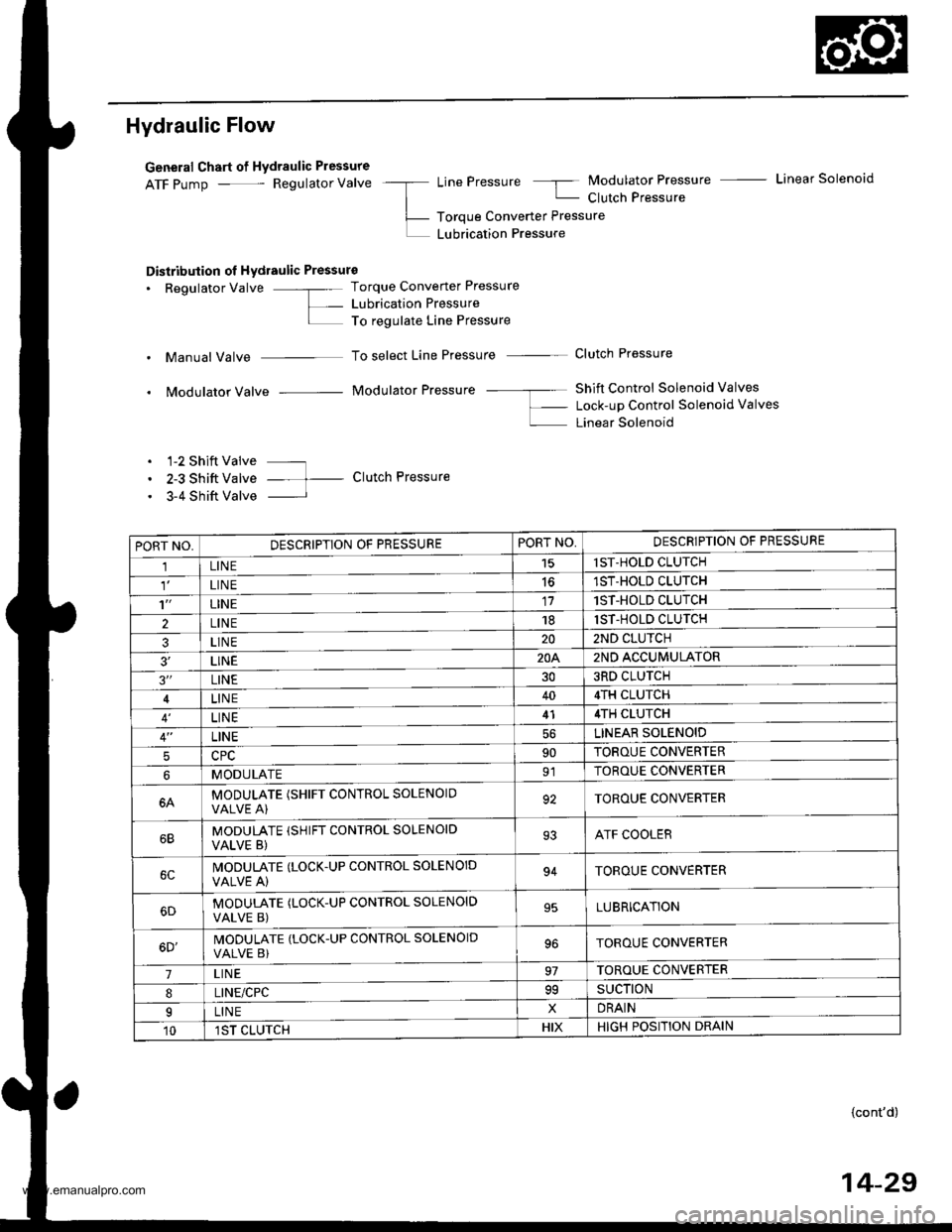
Hydraulic Flow
General Chart of Hydraulic Pressure
ATF pump - Regulator Valve -a LinePressure 5 Modulator Pressure - Linear Solenoid
| - Clutch Pressure
L- Toroue Converter Pressure
L LUbrication Pressure
Distribution ol Hydraulic Pressure
. Regulator Valve -"- Torque Converter Pressure
L- Lubrication PressureI To regulate Line Pressure
. Manual Valve To select Line Pressure - Clutch Pressure
. Modulator Valve Modulator Pressure -- ---- Shift Control Solenoid Valves
f- Lock-up Control Solenoid valves
L Linear Solenoid
. 1-2 Shift Valve ---
. 2-3 Shift Valve -- t- Clutch Pressure
. 3-4 Shift Valve I
PORT NO,DESCRIPTION OF PRESSUREPORT NO,DESCRIPTION OF PRESSURE
1LINE15lST-HOLD CLUTCH
LIN E1ST-HOLD CLUTCH
't'LINE171ST-HOLD CLUTCH
2LINE181ST-HOLD CLUTCH
3LINE202ND CLUTCH
3'�LINE20A2ND ACCUMULATOR
3"LINE303RD CLUTCH
LINE404TH CLUTCH
LINE414TH CLUTCH
LINELINEAR SOLENOID
590TOROUE CONVERTER
MODULATE91TOROUE CONVERTER
6AMODULATE (SHIFT CONTROL SOLENOIOVALVE A)92TOROUE CONVERTER
MODULATE (SHIFT CONTROL SOLENOID
VALVE B)93ATF COOLER
IVODULATE (LOCK.UP CONTROL SOLENOID
VALVE A)94TOROUE CONVERTER
MODUTATE (LOCK-UP CONTROL SOLENOID
VALVE B)95LUBRICATION
6D'MODULATE (LOCK-UP CONTROL SOLENOID
VALVE B)TOROUE CONVERTER
7LIN E97TOROUE CONVERTER
8LINE/CPC99SUCTION
ILINExDRAIN
101ST CLUTCHHIXHIGH POSITION DRAIN
{cont'd)
14-29
www.emanualpro.com
Page 546 of 1395
Description
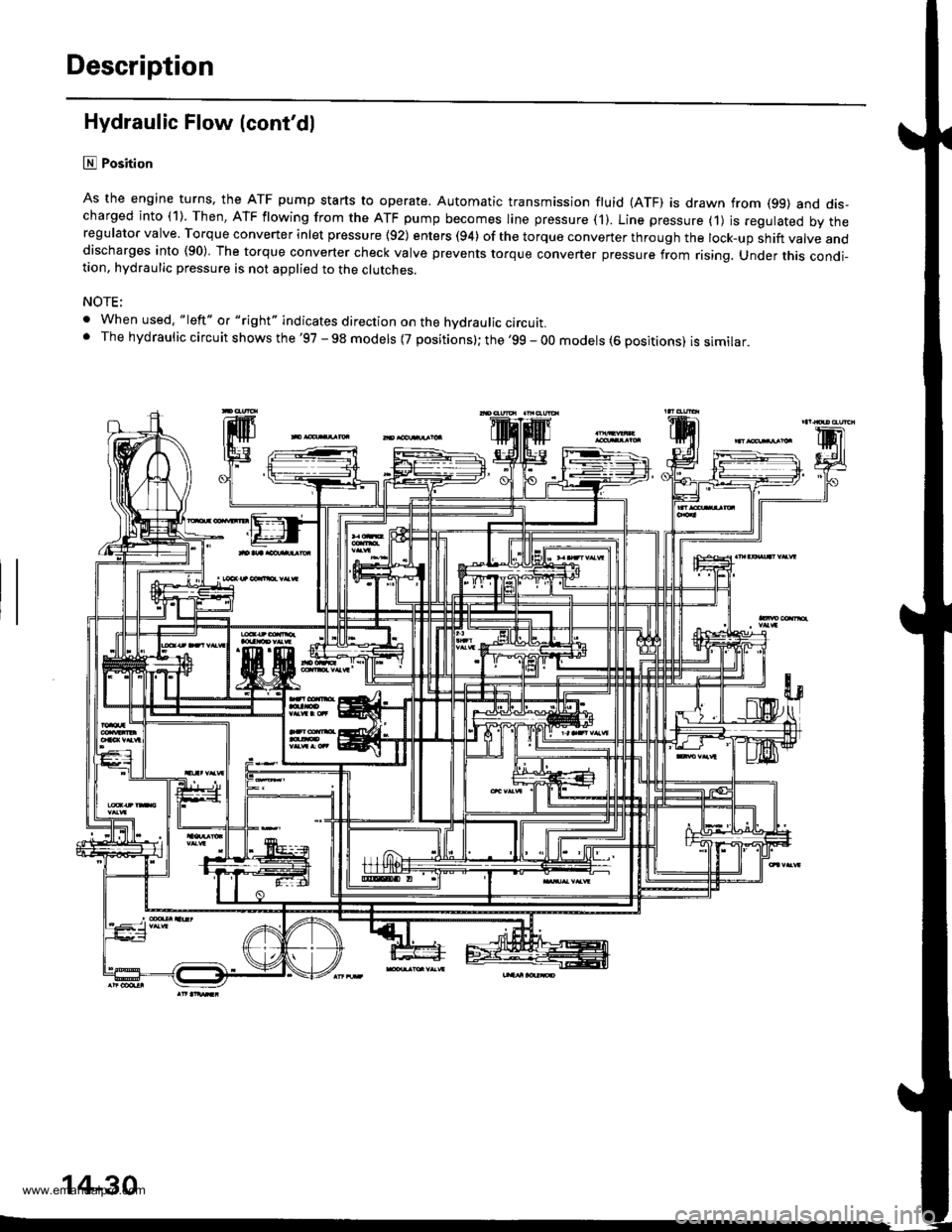
Hydraulic Flow (cont'dl
lll Position
As the engine turns, the ATF pump starts to operate. Automatic transmission fluid (ATF) is drawn from (99) and dis-charged into (1). Then, ATF flowing from the ATF pump becomes line pressure ('l). Line pressure (1) js regulated by theregulator valve. Torque converter inlet pressure {92) enters (94) of the torque conveTter through the lock-up shift valve anddischarges into (90) The torque converter check valve prevents torque converter pressure from rising. Under this condi-tion, hydraulic pressure is not applied to the clutches.
NOTE;
. When used. "|eft" o. "right" indicates direction on the hvdraulic circutt.. The hydraulic circuit shows the '97 - 98 models {7 positions}; the '99 - 00 models (6 positions) is similar.
'lF'.j.l
14-30
www.emanualpro.com
Page 547 of 1395
B Position
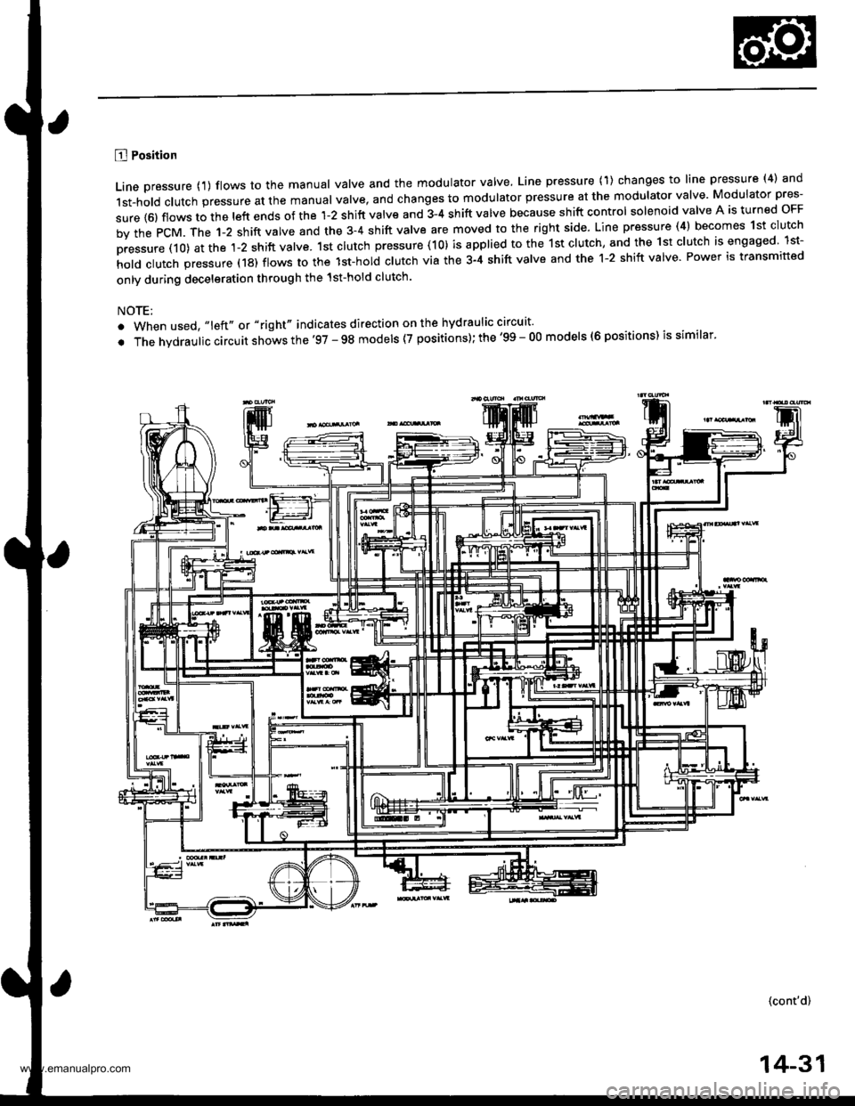
Line pressure {1) flows to the manual valve and the modulator valve, Line pressure (1) changes to line pressure (4) and
1st-hold clutch pressure at the manual valve, and changes to modulator pressure at the modulator valve Modulator pres-
sure {6) flows to the left ends of the 1-2 shift valve and 3-4 shift valve because shift control solenoid valve A is turned oFF
by the PcM. The 1-2 shift valve and the 3-4 shift valve are moved to the right side. Line pressure (4) becomes 1st clutch
pressure (10) at the 1-2 shift valve. 1st clutch pressure (10) is applied to the 1st clutch, and the 1st clutch is engaged lst-
hold clutch pressure (18) flows to the lst-hol; clutch via the 3-4 shift valve and the 1-2 shift valve Power is transmitted
only during deceleration through the 1st-hold clutch.
NOTE:
. When used, "left" or "right" indicates direction on the hydraulic circuit'
. The hvdraulic circuit shows the'97 - 98 models (7 positions); the '99 - O0 models (6 positions) is similar'
(cont'd)
14-31
www.emanualpro.com
Page 548 of 1395
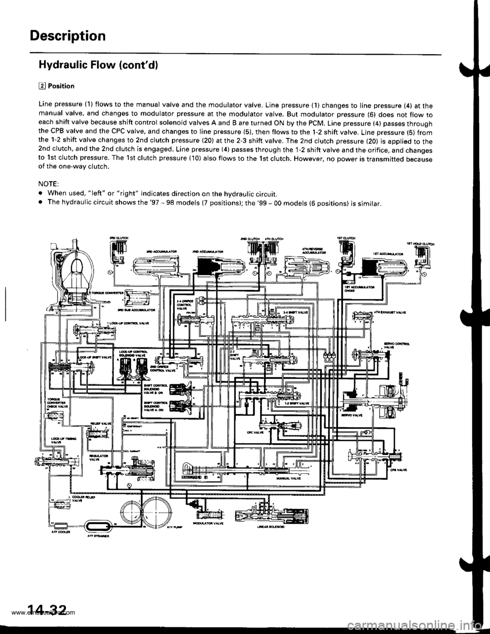
Description
Hydraulic Flow (cont'dl
l?J Position
Line pressure {1) flows to the manual valve and the modulator valve. Line pressure (1} changes to line pressure (4) at themanual valve, and changes to modulator pressure at the modulator valve. But modulator pressure {6} does not flow toeach shift valve because shift control solenoid valves A and B are turned ON by the PCM. Line pressure (4) passes throughthe CPB valve and the CPC valve, and changes to line pressure (5), then flows to the 'l-2 shift valve. Line pressure (5) fromthe 1-2 shift valve changes to 2nd clutch pressure (20) at the 2-3 shift valve. The 2nd clutch pressure (20) is applied to the2nd clutch, and the 2nd clutch is engaged, Line pressure (4) passes through the 1-2 shift valve and the orifice, and changesto lst clutch pressure. The 1st clutch pressure {10) also flows to the 1st clutch. However, no power is transmitted becauseof the one-way clutch.
NOTE:
. When used, "left" or "right" indicates direction on the hvdraulic circuit.. The hydraulic circuit shows the '97 - 98 models (7 positions); the '99 - OO models (6 positions) issimilar.
14-32
www.emanualpro.com
Page 549 of 1395
![HONDA CR-V 1998 RD1-RD3 / 1.G Manual PDF
E] or E Position (97 - 98 Models), and D Position (99 - 00 Modelsl
1. lst Gear
Fluid flow through the torque converter circuit is the same as in E] position. Line pressure flows to the manual valve HONDA CR-V 1998 RD1-RD3 / 1.G Manual PDF
E] or E Position (97 - 98 Models), and D Position (99 - 00 Modelsl
1. lst Gear
Fluid flow through the torque converter circuit is the same as in E] position. Line pressure flows to the manual valve](/img/13/5778/w960_5778-548.png)
E] or E Position ('97 - 98 Models), and D Position ('99 - 00 Modelsl
1. lst Gear
Fluid flow through the torque converter circuit is the same as in E] position. Line pressure flows to the manual valve
and the modulator valve. Line pressure changes to modulator pressure (6) at the modulator valve and to line pressure
{4) at the manual valve. Modulator pressure (6) flows to the left end of the 1-2 shift valve and the 3-4 shift valve
because shift control solenoid valve A is turned oFF and B is turned oN by the PcM. The 1-2 shift valve is moved to
the right side. Line pressure {4) changes to 'lst clutch pressure (10} at the 1-2 shift valve and the orifice The 1st clutch
pressure (10) is applied to the 1st clutch and the 1st accumulator; the vehicle will move as the engine power is trans-
mitted.
NOTE:
. When used, "left" or "right" indicates direction on the hydraulic circuit.
. The hvd rau lic circuit shows th e '97 - 98 models (7 positions); the '99 - 00 models {6 positions) issimilar.
(cont'dl
14-33
www.emanualpro.com