fan HONDA CR-V 1998 RD1-RD3 / 1.G Manual PDF
[x] Cancel search | Manufacturer: HONDA, Model Year: 1998, Model line: CR-V, Model: HONDA CR-V 1998 RD1-RD3 / 1.GPages: 1395, PDF Size: 35.62 MB
Page 1122 of 1395
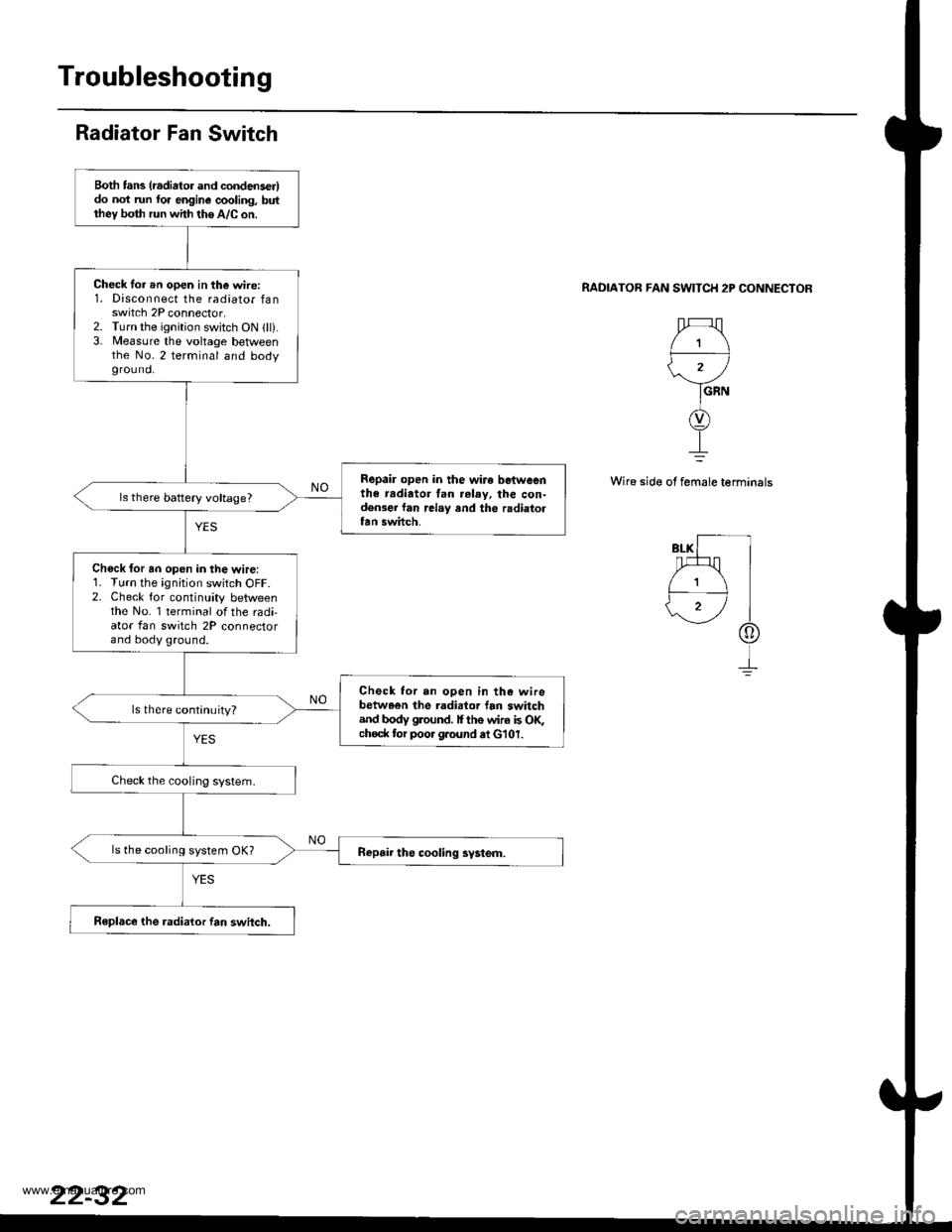
Radiator Fan Switch
RADIATOB FAN SWITCH 2P CONNECTOR
1
'.r
GRN
Wire side of female terminals
Both tans (radiator and condenser)do not run fo. engine cooling, butthey both run with the A/C on.
Check lor rn open in the wire:1. Disconnect the radiator fanswitch 2P connector.2. Turn the ignition switch ON lll).3, Measure the voltage betlveenthe No.2 terminal and bodygrou nd.
Repair open in the wire betweenthe radiator tan relay, the con-densei lan .elay and the radiaiortan swhch.
ls there battery voltage?
Chock for an open in the wire:1. Turn the ignition switch OFF.2. Check for continuity betweenthe No. 1 terminal of the radi-ator fan switch 2P connectorand body ground.
Check for an open in the wirebetween the .adialor fan switchand body glound. I ths wire is OF;choc* tor poor g.ound at G'101.
ls there continuity?
ls the cooling system OK?
Replsce the radialor fan switch.
www.emanualpro.com
Page 1123 of 1395
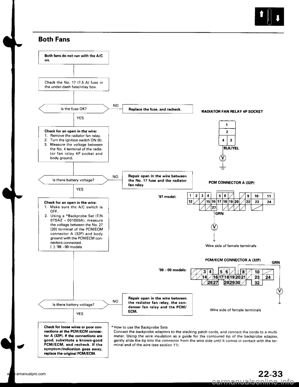
Both Fans
RADIATOR FAN RELAY 'P SOCKET
BLK/YEL
PCM CONNECTOR A I32PI
'9? model:
PCM/ECM CONNECTOR A (32PI
'98 - 0O mod6ls:
Wire side of female terminals
* How to use the Backprobe SetsConnect the backprobe adapters to the stacking patch cords, and connect the cords to a multimeter. Using the wire insulation as a guide for the contoured tip of the backprobe adapter,gently slide the tip into the connector from the wire side until it comes in contact with the terminal end ofthe ware {see section l1).
Check the No. 17 (7.5 A) tuse inthe under-dash fuse/relay box.
Reolace the tuse. and recheck.
Check for an op€n in the wire:1. Remove the radiator fan relay.2. TLrrn the ignition switch ON (ll).
3. Measure the voltage betweenthe No.4 terminalofthe radiator fan relay 4P socket andbody ground.
Repair open in the wire betweenlhe No. 17 luse and the radiatortan relay.
Check for an open in the wire:1. Make sure the A/C switch isOFF.2. Using a *Backprobe Set {T/N07SAZ - 001000A), measurethe voltage between the No. 27I20l terminal ol the PCM/ECMconnector A (32P) and bodyground with the PCM/ECM con-nectors connected.[ ]: '98 - 00 models
Repair open in the wire b€tweenthe.adiator fan ralav, the con-denser tan rolay and the PCM/ECM.
Check tor loose wires or poor con-nodions at the PCM/ECM connoc-tor A (32P1. lf the connections arcgood, substitute a known-goodPCM/ECM, and recheck. It thesymptom/indicalion goes away,r.plrce the original PCM/ECM.
1
2
1
12461011
12t5t61718r9222321
GRN
Wire side oI female terminals
22-33
www.emanualpro.com
Page 1127 of 1395
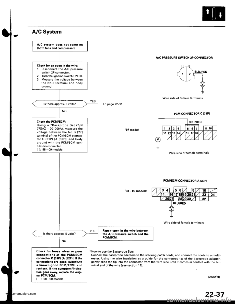
A/C aystem does not come on{both fans and comDrossor).
Ch6ck lor .n open in the wire:1. Disconnect the A,/C pressureswitch 2P connector.2. Turn the ignition switch ON (ll).
3. Measure the voltage betweenthe No.2 terminal and bodyground.
ls there approx. 5 volts?
check tho PcM/EcM:Using a *Backprobe Set (T/N
07SAZ 0010004). measure thevoltage between the No.5 t27lterminal of the PCM/ECM connec,tor C (31P) [A 132P)l and bodyground with the PCM/ECM con-nectors connected,I l: '98 - 00 models
Rop.ir open in th6 wire botweonthe A/C Dr*sure switch and thePCM/ECM.
ls there approx.5 volts?
Check tor loo3e wires or Doorconnections at the PCM/ECMconnoctor C l3lPl lA (32Pll. It theconnections arg good, 3ubdtitut€a known-good PCM/ECM, andrecheck. ll the 3ymptom/indica-tion go.. eway, r€placo thG origi-nal PCM/ECM,[ ]: '98 -00 models
A/C System
A/C PRESSURE SWITCH 2P CONNECTOR
fo page 22-38
PCM CONNECTOR C (31PI
'97 modol:
Wire side of female terminals
PCM/ECM CONNECTOR A I32P'
38 - 00 modeb:
Wire side of female terminals
* How to use the Backprobe SetsConnect the backprobe adapters to the stacking patch cords, and connect the cords to a multi-meter. Using the wire insulation as a guide for the contoured tip ol the backprobe adapter,gently slide the tip into the connector from the wire side until it comes in contact with the ter.minalond olthe wire (see section 11).
(cont'd)
22-37
www.emanualpro.com
Page 1135 of 1395
Relays
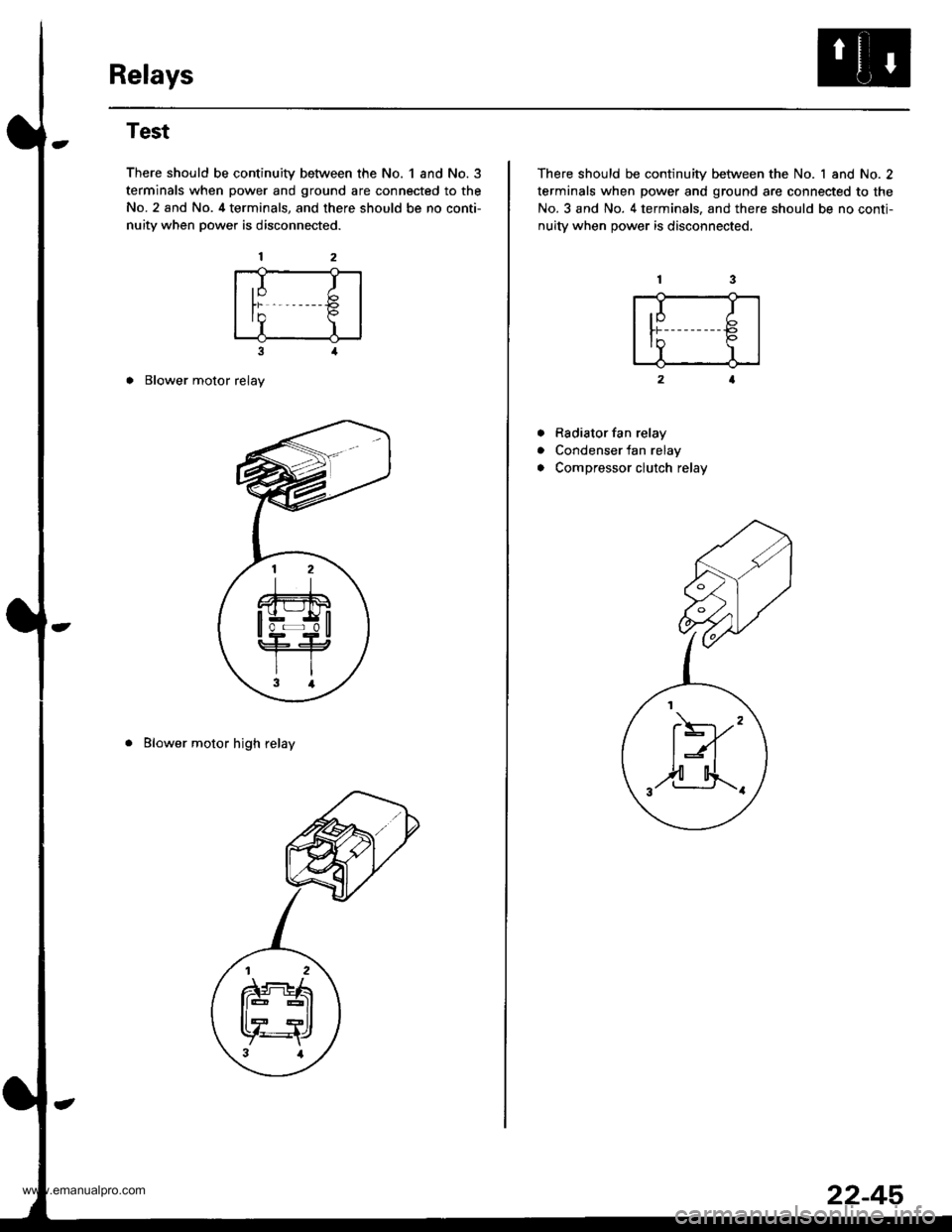
Test
There should be continuity between the No. 1 and No.3
terminals when power and ground are connected to the
No. 2 and No. 4 terminals, and there should be no conti-
nuity when power is disconnected.
3
o Blower motor relay
. Blower motor high relay
,I It)
In P
I)
There should be continuity between the No. 1 and No. 2
terminals when power and ground are connected to the
No. 3 and No. 4 terminals, and there should be no conti-
nuitv when oower is disconnected.
Rsdiator fan relay
Condenser fan relay
Compressor clutch relay
a
a
.I I
tr€
II
F)'"
,2-4.._.
22-45
www.emanualpro.com
Page 1146 of 1395
A/G System Service
Performance Test
The performance test will helD determine if the air con-
ditioner system is operating within specifications.
Use only service equipment that is U.L.-listed and is cer-
tified to meet the requirements of SAE J2210 to remove
HFC-134a (R-134a) from the air conditioner svstem.
CAUTION: Exposure to air condiiioner r€trigerant and
lubricant vapor or mist can irritate €yes, nose and
throat. Avoid bre8thing the air conditioner retrige.ant
and lubricant vapor or mist,
lf accidental system discharge occurs. ventilate work
area before resuming service.
R-134a service equipment o. vehicle air conditioner sys-
tems should not be pressure tested or leak tested with
comDressed air.
@ some mixtur€s ol air and R-134a have becn
shown to be combuslible at olsvated pressures and can
result in lire or explosion causing iniury or property
damage. Never use compressed air to prgssure test R-
13i[a service equipment or vehicle air conditioner sys.
tems.
Additional health and safety information may be obtained
from the refrigerant and lubricant manufacturers.
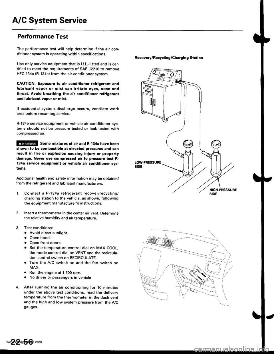
Recovory/Recycling/charging station
LOW.PRESSURESIDE
1.Connect a R-134a refrigerant recover/recycling/
charging station to the vehicle, as shown. following
the equipment manufacturer's instructions,
Insen a thermometer in the center air vent. Determine
the relative humidity and air temperature.
Test conditions:
. Avoid direct sunlight.
o Open hood.
. open front doors.
. Set the temperature control dial on MAX COOL,
the mode control dial on VENT and the reci.cula-
tion control switch on RECIRCULATE.
. Turn the A,/C switch on and the fan switch on
MAX.
. Run the engine at 1,500 rpm.
. No driver or passengers in vehicle
After running the air conditioning for 10 minutes
under the above test conditions, read the deliverv
temperature from the thermometer in the dash vent
and the high and low system pressure from the Ay'Cgauges.
2.
22-56
www.emanualpro.com
Page 1148 of 1395
A/C System Service
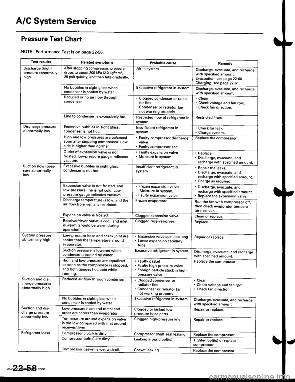
Pressure Test Chart
NOTE: Performance Test is on page 22-56.
Test resultsRelatad symptomsPrcbable caus€Remody
Discharge (high)pressure 6bnormallyhagh
After stopping compressor, pressuredrops to about 200 kPa 12.0 kgtlcm,,28 psi) quickly, and then lalls gradualty.
Air in systemDischarge, evacuate, and rechargewith specified amount.Evacuation: see page 22-60Charging: see page 22-61No bubbles in sight glass whencondenser is cooled by waterExcessive refrigerant in systemDischarge, evacuate, and rechargewith specilied amount.Reduced or no air flow throughcondenser. Clogged condenser or radia-tor fins. Condenser or radiator fannot wo.king properly
CleanCheck voltage and fan rpm.Check fan direction.
Line to condensor is excossivelv hot.Restricted flow of relrigerant insy$emFestricted lines
Discharge pressureabnormally lowExcessive bubbles in sight glass;condenser is not hot.Insufficient retrigerant inCheck for leak.Charge system.High and low pressures are balancedsoon after stopping compressor. Lowside is higher than normal.
. Faulty compressor discharge
. Faulty compressor seal
Replace the comprossor.
Outlet ot expansion valve is notfrosted, low-pressure gauge indicates
' Faulty expansion valve. Moisture in system. Replace. Discharge, evacuate, andrecharge with specified amount.Suction {low) pros,sure abnormallyExcessive bubbles in sight glass;condenser is not hot.Insufficiont relrigerant inRepair the leaks.Discharge, evacuate, andrecharge with specified amount.Charge as r€quired.Expansion valve is not frosted, andlow-pressure line is not cold. Low-pressure gauge indicates vacuum.
' Frozen expansion valvelMoisture in system). Faulty expansion valve
. Discharge, evacuate, andrecharge with specitied amount.. Replace th€ expansion valve.Discharge temperature is low, and theair llow trom vents is restricted.Frozen evaporatorRun the fan with compressor off,then check evaporator tempera,ture sensor.Expansion valve is frosted.Clogged expansion valveClean or replace.Feceiver/dryer outlet is cool, and inlotrs w6rm (should be warm duringoperation).
Clogged receiver/dryerReplace
Suction pressureabnormally highLow-pressure hose and check joint arecooler than tho temperature aroundevaporator.
. Expansion valve open too long. Loose expansion capillarytube
Repair or roplace.
Suction pressure is lowored whencondenser is cooled by water.Excessive refrigerant in systemDischarge, evacuate, and rechargewath specified amount.High and low-pressure are equalizedas soon as tho compressor is stopped,and both gauges tluctuate whilerunning.
Faulty gasketFaulty high-pressure valveForeign panicle stuck in high-
Replace the compressor.
Slction and dis,charge pressutesabnormally high
Reduced air flow through condens€r,. Clogged condenser orradiator tins. Condenser or radiator fannot working properly
CleanCheck voltage and fan rpm.Check Ian direction.
No bubbles in sight glass whencondenser is cooled by walerExcessive refrigerant jn systemDischarge, evacuate, and rechargewith specified amount.Suction and dis-charge pressureabnormally low
Low-pressure hose and motalendareas are cooterlhan evaporator.Clogged or kinked low-pressure hose pansRepair or replace.
Temperature around expansion valvers too low compared with that aroundClogged high-pressure lineRepair or replace.
Refrigerant leaksCompressor clutch is diny.Compressor shaft seal leakingReplace the compressor.Compressor boltls) are dirty.Leaking around bolt(s)Tighton bolt{s) or replacecompressor.Compressor gasket is wet with oil.Gasket leakingReplace the compressor,
www.emanualpro.com
Page 1152 of 1395
Compressor
Replacement
lf the compressor is marginally operable. run the
engine at idie speed, and let the air conditioner
work for a few minutes. then shut the engine off.
Disconnect the negative cable from the battery.
Recover the refrigerant with a recovery/recycling/
charging station (see page 22-59).
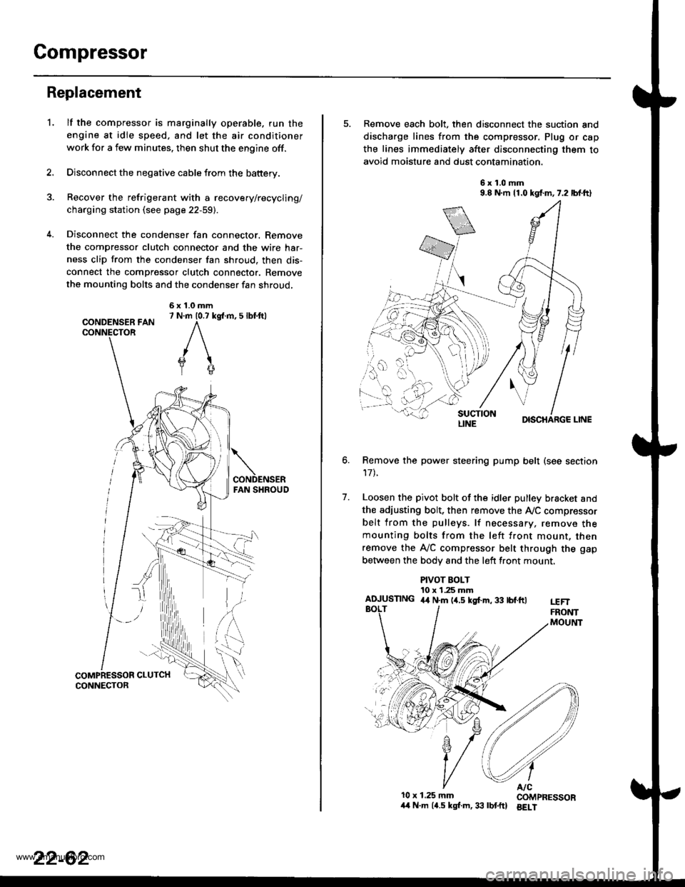
Disconnect the condenser fan connector. Remove
the compressor clutch connector and the wire har-
ness clip from the condenser fan shroud, then dis-
connect the compressor clutch connector. Remove
the mounting bolts and the condenser fan shroud,
CONDENSER FANCONNECTOR
6x1.0mm7 N.m 10.7 kg{.m, 5 lbl.ftl
'L
2.
5. Remove each bolt, then disconnect the suction and
discharge lines from the compressor. Plug or cap
the lines immediately after disconnecting them to
avoid moisture and dust contamination,
6x1.0mm9.8 N.m 11.0 kgf.m,7.2 lbf.ft)
DISCHARGE LINE
Remove the power steering pump belt (see section
17t.
Loosen the pivot bolt of the idler pulley bracket and
the adiusting bolt, then remove the Ay'C compressor
belt from the pulleys. lf necessary, remove themounting bolts from the left front mount, thenremove the A,/C compressor belt through the gap
between the bodv and the left front mount.
6.
7.
PIVOT BOLT10 x 1.25 mmAIUUSTING 4,t N.m (4.5 kgf.m, 33 tbf.ftlt€FTFRONTMOUltlT
10x 1.25 mm COMPRESSOR/t4 N.m (4.5 kgl.m,33 lbtftl BELI
LINE
www.emanualpro.com
Page 1161 of 1395

Body Electrical
Speciaf Toofs ,...,..,.............-.23-2
Troubleshooting
Tips and Precautions ......,.,..........,.................. 23-3
Five-step Troubleshooting ........,.,.,...,,.,......... 23-5
Wire Color Codes ...,....,.. 23-5
Relay and Control Unit Locations
Engine Compartment ..,.,......,......................... 23-6
Dashboard ,.,.,..............-.- 23-7
Door ....................... .........23-10
Index to Cilcuits and Sysiems
Accessory Socket .. ,....,.,..,.,. 23-95*Airbags ................ .,....,. Sestion 24
Air Conditioning ,.,.,.... Section 22
Alternator ................... Section 4
Anti-lock Brake System {ABSI ................... Section 19'A/T Gear Position Indicator ....................... Section 1,1
Automatic Transmission System ...........,.. Section 14
Battery ................... ..............23-50
Blower Controls .,...,.,, Section 22
Charging System ....... Seqtion il
Clock -'98 Model ................ 23-98
Connector ldentification and Wire HarnessRouting .................. ......... 23.11
Cruise Control ............ Ssction 4
Dash Lights Brightness Contlo||er ..................... 23-90
Fan Conlrols ...,......,.... Section 10
Fuel Pump ,..,.,...,....,.... Section 11
Fuses...................... .,,.,.,.,.,,.,23-40*Gauges
Circuit Diagram ......-....-..23-58
Fuel Gauge .....,.,..... Section 11
Speedometer ..,..........,... 23-56
Ground Distribution ,....,.,...23-46
Hatch Glsss ODenor .........................,.,.,.,.,..,.,.,.,,. 23-121
Heater Controls .-........ Soction 21*Horns.,...,..,.,.,....... ................23"104*fgnition Switch ,,.,.,..,.,.,,.,.,.,23-51
lgnition Key Light System -'97 Mod6l .............. 23.88
-+
BODY
www.emanualpro.com
Page 1166 of 1395
Relay and Control Unit Locations
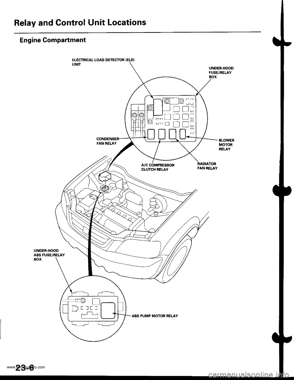
Engine Compartment
ELECTRICAL LOAD DETECTOR IELDIUNITUNDER.HOODFUSE/RELAYBOX
BLOWERMOTORRELAY
A/C COMPRESSORCLUTCH RELAY
RADIATORFAN EELAY
UNDER.HOODABS FUSE/RELAYBOX
t:
tr
tr
tr
;
-
''r@
Dl-- r rr r
23-6
www.emanualpro.com
Page 1174 of 1395
![HONDA CR-V 1998 RD1-RD3 / 1.G Manual PDF
Connector ldentification and Wire Harness Routing
Engino Wire Harness
Connecto; or
Terminal
Number of
CavitiesLocationConneqts toNotos
c101
c102
c103
c 104
c105
c105
c106
c 107
c 108
c 109
c]10
c1ll HONDA CR-V 1998 RD1-RD3 / 1.G Manual PDF
Connector ldentification and Wire Harness Routing
Engino Wire Harness
Connecto; or
Terminal
Number of
CavitiesLocationConneqts toNotos
c101
c102
c103
c 104
c105
c105
c106
c 107
c 108
c 109
c]10
c1ll](/img/13/5778/w960_5778-1173.png)
Connector ldentification and Wire Harness Routing
Engino Wire Harness
Connecto; or
Terminal
Number of
CavitiesLocationConneqts toNotos
c101
c102
c103
c 104
c105
c105
c106
c 107
c 108
c 109
c]10
c1l'l
c112
c113
c't 14
cl16
cl16
c117
c118
c119
c120
c121
c't22
c't23
c't25
cl26
cl27
cr 28
cl29
c130
c131
c132
c 133
c134
c134
c135
c 136
10
6
1
2
1
2
1
10
20
31
16
22
l0
l0'14
14
1
Left side of engine compartment
Left side of engine compartment
Middle of engine
Middle of engine
Left side of engine compartment
Left side of engine compartment
Middle of engine
Middle of engine
Middle of engine
Middle of engine
Middle of engine
Middle of engine
Middle of engine
Middle of engine
Middle of engine
Middle of engine
Middle of engine
Middle of engine
Middle of engine
Middle of engine
Middle of engine
Right side of engine
Middle of engine
Behind right kick panel
Under right side of dash
Under right side of dash
Under right side of dash
Under right side of dash
Under right side of dash
Right side of engine
Right side of engine
Middle of engine
Middle of engine
Middle of engine
Middle of engine
Middle of engine
Middle of engine
Left side of engine compartment
Middle of engine
Middle of engine
Main wire harness (C304)
Main wire harness (C305):'97 - 98 models
No. 1 fuel injector
Crankshaft speed fluctuation (CKF) sensor
Alternator
Alternator
Engine oil pressure switch
No.2 fuel injector
Evaporative emission (EVAP) purge
control solenoid valve
No. 3 fuel injector
No. 4 fuel injector
Primary heated oxygen sensor(Primary HO2S) (sensor 1)
Radiator fan switch
Coolant temperature sending unit
Engine coolant temperature (ECT) sensor
Mainshaft speed sensor
Lock-up control solenoid valve
Back-up light switch
Shift control solenoid valve
Linear solenoid valve
Countershaft speed sesnsor
Starter solenoid
Distributor
Junction connector
PCM
ECIWPCM
ECM/PCM
ECM/PCM
Main wire harness (C,|:}1)
IVT gear position switch
Vehicle speed sensor (VSS)
Throttle position (TP) sensor
MAP sensor
ldle air control (lAC)valve
lntake air temperature (lAT) sensor
Junction connector
Junction connector
Power steering pressure (PSP) switch
Junction connector
Knock sensor (KS)
A/r
USA
Canada
Alr
AlT
M/'r
Afi
'97mooel
'97 model'98 - 00
mooets
'99 - 00
models
T101
r102
Left side of en0ine companment
Right side of engine compartment
Alternator
Under-hood fuse/relay box
G101Middle of engineEngine ground, via engine wire harness
23-14
www.emanualpro.com