Door HONDA CR-V 1998 RD1-RD3 / 1.G Manual Online
[x] Cancel search | Manufacturer: HONDA, Model Year: 1998, Model line: CR-V, Model: HONDA CR-V 1998 RD1-RD3 / 1.GPages: 1395, PDF Size: 35.62 MB
Page 1230 of 1395
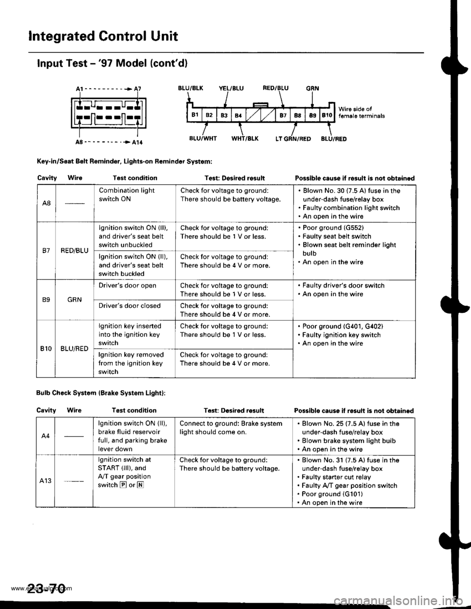
lntegrated Control Unit
Input Test -'97 Model (cont'd)
At----------+A7
Key-in/Seat Belt Reminder, Lights-on Remindor System:
Cavity WireTest conditionTest: Desired rosultPossible cause if re3ult is nol obtainod
Bulb Check System (Brake System Light):
Cavity WireTest conditionT6st: DGsirgd rosultPossible cause if resuh is not obtainod
23-70
A8
Combination light
switch ON
Check for voltage to ground:
There should be battery voltage.
Blown No.30 (7.5 A) fuse in the
under-dash fuse/relay box
Faulty combination light switch
An open in the wire
B7R ED/BLU
lgnition switch ON {lll.
and driver's seat belt
switch unbuckled
Check for voltage to ground:
There should be 1 V or less.
Poor ground (G552)
Faulty seat belt switch
Blown seat belt reminder light
bulb
An open in the wirelgnition switch ON (ll),
and driver's seat belt
switch buckled
Check for voltage to groundl
There should be 4 V or more.
B9GRN
Driver's door openCheck ior voltage to ground:
There should be 1 V or less.
. Faulty driver's door switch. An open in the wire
Driver's door closedCheck for voltage to ground:
There should be 4 V or more.
810BLU/RED
lgnition key insened
into the ignition key
switch
Check for voltage to ground;
There should be 1 V or less.
Poor ground (G401, G,[02)
Faulty ignition key switch
An open in the wire
lgnition key removed
trom the ignition key
swrtch
Check for voltage to ground:
There should be 4 V or more.
A4
lgnition switch ON { ll),
brake fluid reservoir
full, and parking brake
tever oown
Connect to ground: Brake system
light should come on.
Blown No. 25 (7.5 A) iuse in the
under-dash fuse/relay box
Blown brake system light bulb
An open in the wire
A13
lgnition switch at
START (lll), and
A/T gear position
switch E or E
Check for voltage to ground:
There should be battery voltage.
Blown No.31 (7.5 A) fuse in the
under-dash fuse/relay box
Faulty starter cut relay
Faulty A/f gear position switch
Poor ground (G101)
An open in the wire
www.emanualpro.com
Page 1234 of 1395
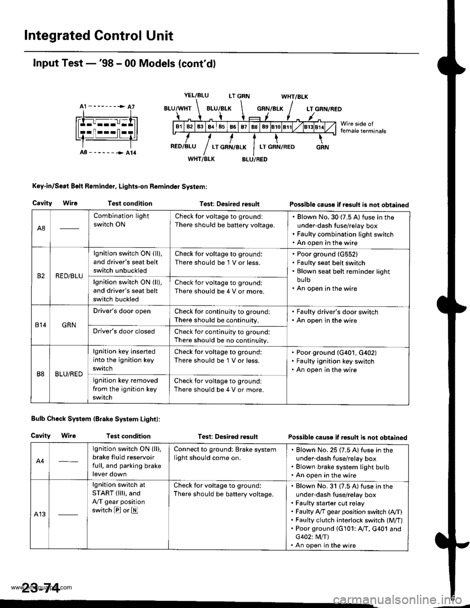
Integrated Control Unit
A1 --------> A7
Input Test -'98 - 00 Models (cont'dl
YEL/BLULT GRNWHT/BLK
GRN/BLKLT GRN/REO
Wire side offemale terminals
A8------->A14WHT/BLK
Key-in/Se8t Beft Reminder, Lights-on Remindol System:
BLU/RED
Cavity WireTest conditionTest: Desired resultPossible caus€ it result is not obtained
Bulb Check System lBrake System Lightl:
Cavity WireTest conditionTest: Desired resultPossible caus€ if result is not obtained
A4
lgnition switch ON (ll),
brake fluid reservoir
full, and parking brake
lever down
Connect to ground: Brake system
light should come on.
Blown No. 25 (7.5 A) fuse in the
under-dash fuse/relay box
Blown brake system light bulb
An open in the wire
A13
lgnition switch at
START ( lll), and
A,/T gear position
switch E or E
Check for voltage to ground:
There should be battery voltage.
Blown No. 31 {7.5 A) fuse in the
under-dash fuse/relay box
Faulty sta rter cut relay
Faulty A,/T gear position switch (A,/T)
Faulty clutch interlock switch (M/T)
Poor ground {G101: AfI. G401 and
G402: M/T)
An open in the wire
23-74
A8
Combination light
switch ON
Check for voltage to ground:
There should be battery voltage.
Blown No. 30 (7.5 A) fuse in the
under-dash fuse/relay box
Faulty combination light switch
An open in the wire
RED/BLU
lgnition switch ON ( ll),
and driver's seat belt
switch unbuckled
Check for voltage to ground:
There should be 1 V or less.
Poor ground {G552)
Faulty seat belt switch
Blown seat belt reminder light
bu lb
An open in the wirelgnition switch ON (ll),
and driver's seat belt
switch buckled
Check for voltage to ground:
There should be 4 V or more.
814GRN
Driver's door openCheck for continuity to ground:
There should be continuity,
. Faulty driver's door switch. An open in the wire
Driver's door closedCheck for continuity to ground:
There should be no continuity.
B8BLU/RED
lgnition key inserted
into the ignition key
swrtch
Check for voltage to ground:
There should be 'l V or less.
Poor ground (G401, G402)
Faulty ignition key switch
An open in the wire
lgnition key removed
from the ignition key
switch
Check for voltage to ground:
There should be 4 V or more.
www.emanualpro.com
Page 1238 of 1395
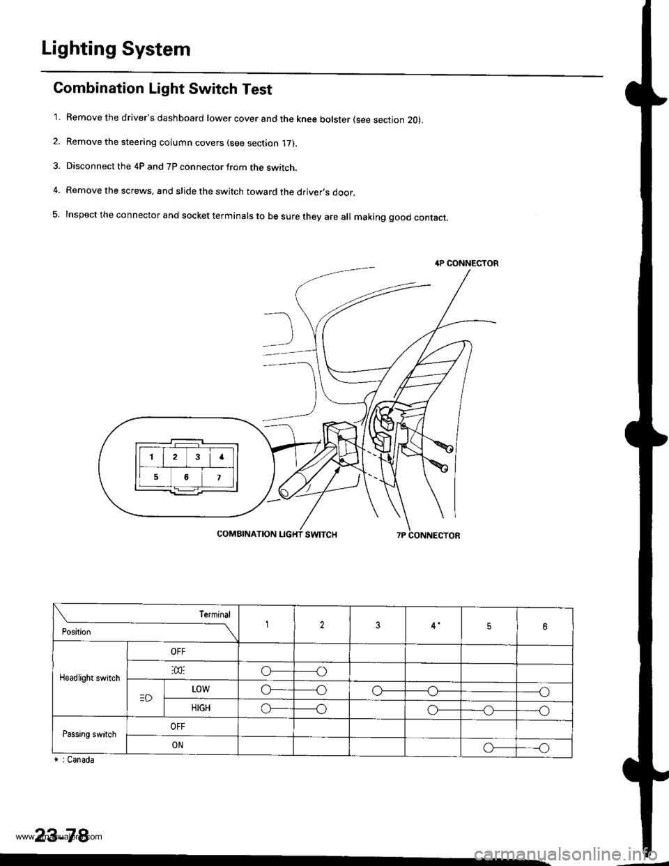
Lighting System
Combination Light Switch Test
'1. Remove the driver's dashboard lower cover and the knee bolster (see section 20).
2. Remove the steering column covers (see section '17).
3. Disconnect the 4P and 7P connector from the switch.
4. Remove the screws, and slide the switch toward the driver,s door,
5. Inspect the connector and socket terminals to be sure they are all making good contact.
r : Canada
23-78
4P CONNECTOR
23I
56
Position
Terminal12356
Headlight switch
OFF
:m:o_----o
=DL0wo------oo-----o
HIGHo_----oo-_--_o_----o
Passing switchOFF
ONo_---o
www.emanualpro.com
Page 1247 of 1395
![HONDA CR-V 1998 RD1-RD3 / 1.G Manual Online
Turn Signal Switch Test
1.
4.
Remove the drivers dashboard lower cover and the
knee bolster (see section 20).
Remove the steering column covers {see section
17]-.
Disconnect the 4P and 7P connectors HONDA CR-V 1998 RD1-RD3 / 1.G Manual Online
Turn Signal Switch Test
1.
4.
Remove the drivers dashboard lower cover and the
knee bolster (see section 20).
Remove the steering column covers {see section
17]-.
Disconnect the 4P and 7P connectors](/img/13/5778/w960_5778-1246.png)
Turn Signal Switch Test
1.
4.
Remove the driver's dashboard lower cover and the
knee bolster (see section 20).
Remove the steering column covers {see section
17]-.
Disconnect the 4P and 7P connectors from the
switch.
Remove the screws, and slide the switch toward the
driver's door.
Check for continuity between the terminals in each
switch position according to the table.
Position
Terminal12
RIGHTo-
Neutral
LEFTo---o
q
tl-
swtTcH
Hazard Warning Switch Test
1. Remove the center panel {see section 20).
2. Remove the two screws, then remove the switch
from the center air vent.
HAZARD
Check for continuitv between the terminals in each
switch position according to the table.
Terminal
t**--\
2357810
OFF(9U(_)
ONo@oooo
lNol us€d)
23-87
www.emanualpro.com
Page 1248 of 1395
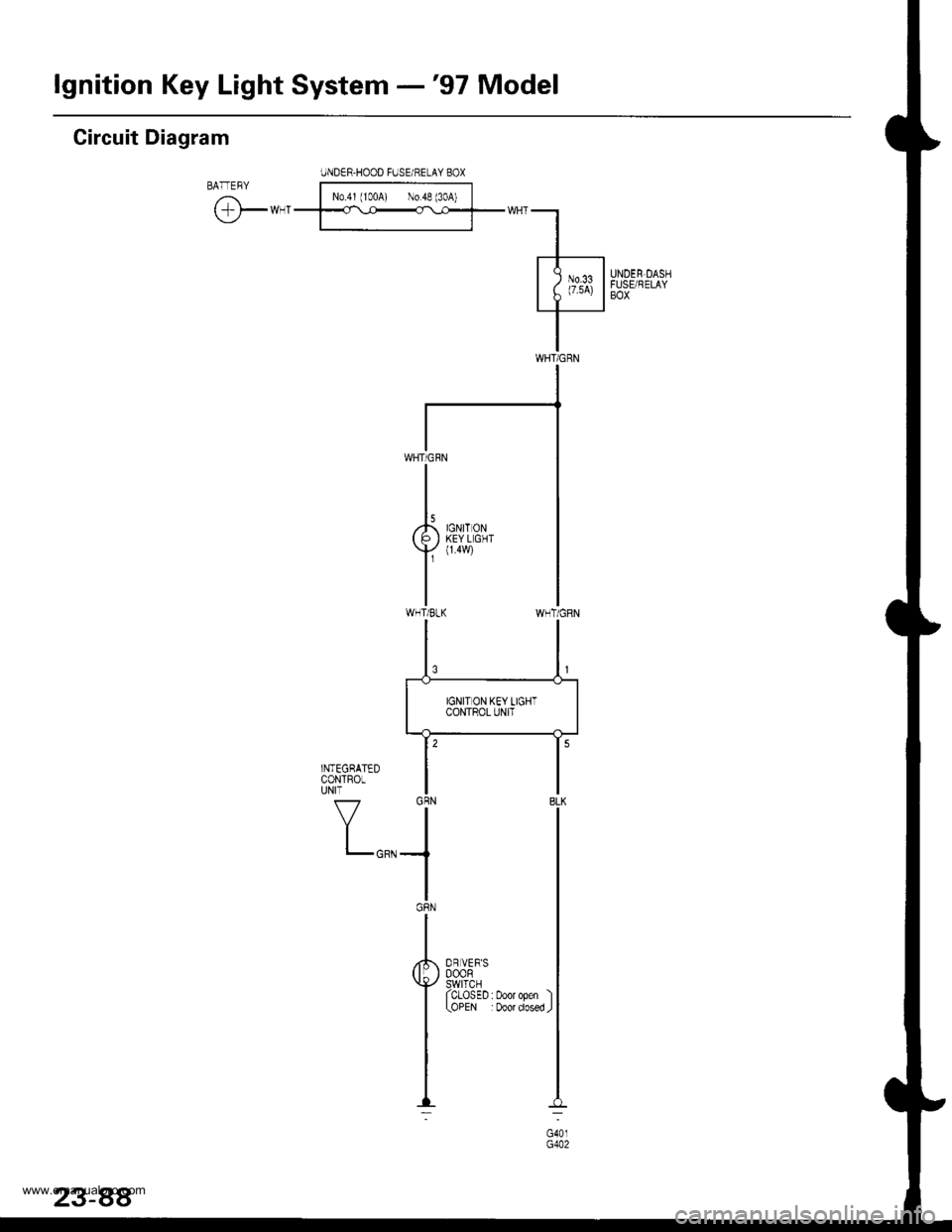
lgnition Key Light System -'97 Model
Circuit Diagram
IJNDER-HOOD FUSE/HELAY BOXBATEBY l-Noj',roo{ l;;f
tF*-'--ff::f-*"-l
.l-----
| ; )"t li|illsx"r
I
WNT/GRN
WHT/CRN
I
,k ,0r,, o,u( P I KEYLGHT
Y
{14w)
IWHT/BLK
OR VER'S000R9!rl9rl^ ^I ULU5EU:UOOrOpen I(OPEN :Door dosed J
www.emanualpro.com
Page 1249 of 1395
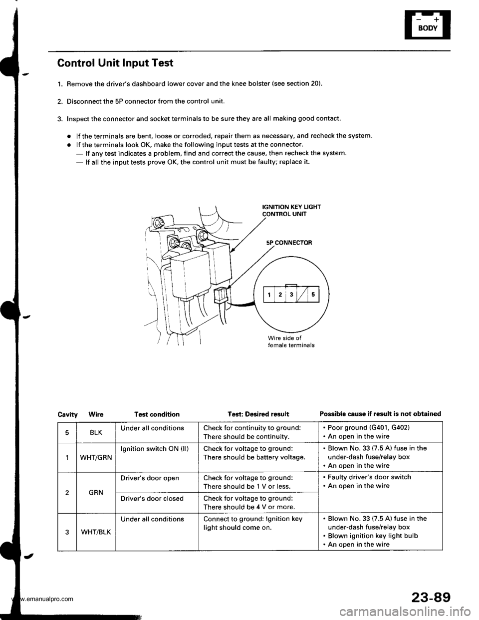
Control Unit Input Test
l. Bemove the driver's dashboard lower cover and the knee bolster (see section 20).
2, Disconnect the 5P connector from the control unit.
3. Inspect the connector and socket terminals to be sure they are all making good contact.
. lf the terminals are bent, loose orcorroded, repairthem as necessary, and recheck the system.
. lf the terminals look OK, make the following input tests at the connector.- lf any test indicates a problem, find and correct the cause. then recheck the system.
- lf all the input tests prove OK, the control unit must be faulty; replace it.
IGNITION KEY LIGHTCONTROL UNIT
5P CONNECTOR
\
))
Test conditionCavityWireTest: Desired resultPossible cause if r€sult is not obtained
BLKUnder all conditionsCheck for continuity to ground:
There should be continuity.
. Poor ground {G401, G402}. An open in the wire
'IWHT/GRN
lgnition switch ON (ll)Check for voltage to ground:
There should be battery voltage.
. Blown No. 33 (7.5 A) fuse in the
under-dash fuse/relay box. An open in the wire
GRN
Driver's door openCheck for voltage to ground:
There should be 1 V or less.
. Faulty driver's door switch. An open in the wire
Driver's door closedCheck for voltage to ground:
There should be 4 V or more.
WHT/BLK
Under all conditionsConnect to ground: lgnition key
light should come on.
Blown No. 33 (7.5 A) fuse in the
under-dash fuse/relay box
Blown ignition key light bulb
An open in the wire
23-89
www.emanualpro.com
Page 1252 of 1395
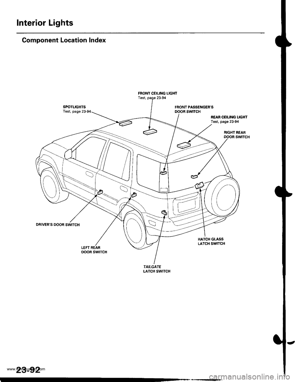
Interior Lights
Component Location Index
SPOTLIGHTSTest, page
DRIVER'S DOOR SWITCH
LEFT REARoooR swtTcH
FRONT CEILING LIGHTTest, page 23-94
FRONT PASSENGER'SDOOR SWITCH
REAR CCILING LIGI{TTest, page 23-94
RIGHT REARswtTcH
HATCH GLASSLATCH SWITCH
TAILGATELATCH SwlTCH
23-92
www.emanualpro.com
Page 1262 of 1395
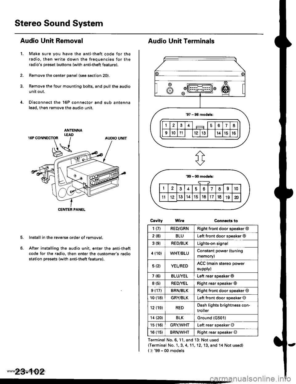
Stereo Sound System
Audio Unit Removal
Make sure you have the anti-theft code for the
radio, then write down the frequencies for the
radio's preset buttons (with anti-theft feature).
Remove the center panel (see section 201,
Remove the four mounting bolts, and pull the audio
unit out.
Disconnect the 'l6P connector and sub antenna
lead, then remove the audio unit.
Install in the reverse order of removal.
After installing the audio unit, enter the anti-theft
code for the radio. then enter the customer's radio
station presets (with anti-theft feature).
1.
AUDIO UNIT
CENTEB PANEL
23-102
Audio Unit Terminals
CavrtyWireConnoct3 to
Terminal No.6, 11, and 13: Not used(Terminal No. 1,3, 4,'11,12, 13, and '14 Not us6d)
{ ): '99 - 00 models
1{7)RED/GRNRight front door speaker @
2 {8}BLULeft front door speaker @
3 {9)RED/BLKLights-on signal
4 (10)WHT/BLUConstant power (tuning
memory)
5 (2)YEUREDACC (main sterso power
supplyl
7 (6)BLU/YELLeft rear soeaker @
8 (s)RE D/VELRight rear speaker @
9 (17)BRN/BLKRiqht f.ont door speaker O
10 (18)GRY/BLKLeft front door soeaker O
12 (19)REDDash lights brightness con-
troller
14 (20)BLKGround (G501)
15 (16)GRYMHTLeft rear speaker O
16 (15)BRN^ll/HTRight resr speaker O
www.emanualpro.com
Page 1263 of 1395
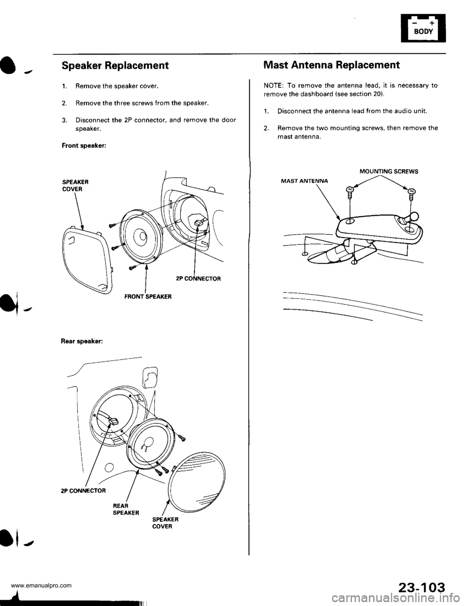
Speaker Replacement
1. Remove the speaker cover.
2. Remove the three screws from the speaker.
3. Disconnect the 2P connector, and remove the door
speaker.
Front speaker:
2P CONNECTOR
Rear speaker:
/a--=-
ll-
FRONT SPEAKER
SPEAKERCOVER
4-
23-103
Mast Antenna Replacement
NOTE: To remove the antenna lead, it is necessary to
remove the dashboard (see section 20).
1. Disconnect the antenna lead from the audio unit.
2. Remove the two mounting screws, then remove the
mast antenna.
MOUNTING SCREWS
www.emanualpro.com
Page 1265 of 1395
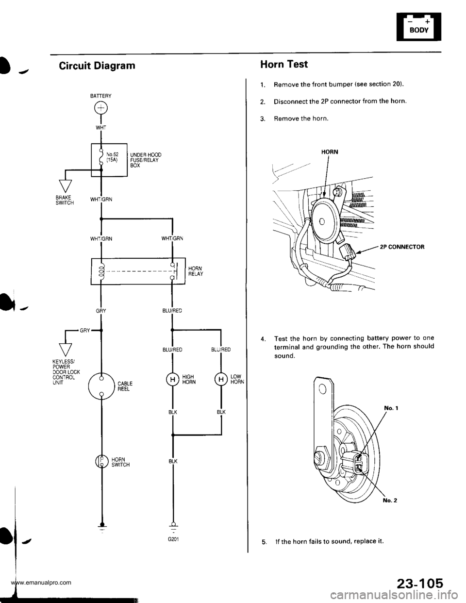
Horn Test
1. Remove the front bumper (see section 20).
2. Disconnect the 2P connector from the horn
3, Remove the horn.
2P CONNECTOR
Test the horn by connecting battery power to one
terminal and grounding the other. The horn should
sound.
4.
HORN
23-105
5. lf the horn fails to sound, replace it
Circuit Diagram
}-BLU/FED
I
BLUi FEO BLU/RED
II
g)iirrN I
tlBLK BLK
ll
IBLK
I
I
I
G201
fl"'
LOWHORN
KEYLESSiPOWEFDOOR LOCKCONTROLUNIT
www.emanualpro.com