Filter assembly HONDA CR-V 1998 RD1-RD3 / 1.G Workshop Manual
[x] Cancel search | Manufacturer: HONDA, Model Year: 1998, Model line: CR-V, Model: HONDA CR-V 1998 RD1-RD3 / 1.GPages: 1395, PDF Size: 35.62 MB
Page 92 of 1395
Cruise Gontrol
Actuator Test (cont'dl
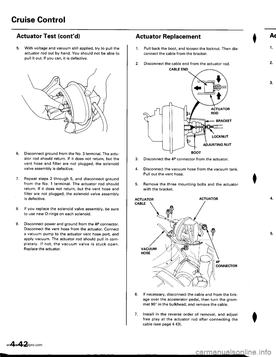
5. With voltage and vacuum still applied, try to pull the
actuator rod out by hand. You should not be able topull it out. lf you can. it is defectrve.
8.
9.
7.
Disconnect ground from the No. 3 terminal. The actu-
ator rod should return. lf it does not return, but the
vent hose and filter are not plugged, the solenoid
valve assembly is defective.
Repeat steps 2 through 5. and disconnect ground
from the No. l terminal. The actuator rod should
return. lf it does not return, but the vent hose and
filter are not plugged, the solenoid valve assembly
is defective.
lf you replace the solenoid valve assembly, be sure
to use new O-rings on each solenoid.
Disconnect power and ground from the 4P connector.
Disconnect the vent hose from the actuator. Connect
a vacuum pump to the actuator vent hose port, and
apply vacuum. The actuator rod should pull in com-pletely. lf not, the vacuum valve is stuck open.
Replace the actuator,
4-42
I
't.
Actuator Replacement
3.
4.
7.
Ar
Pull back the boot. and loosen the locknut. Then dis-
connect the cable from the bracket.
Disconnect the cable end from the actuator rod.
1.
4.
.J.
Disconnect the 4P connector from the actuator.
Disconnect the vacuum hose from the vacuum tank.
Pull out the vent hose.
Remove the three mounting bolts and the actuator
with the bracket.
ACTUATORACTUATOR
CABLE
lf necessary, disconnect the cable end from the link-
age over the accelerator pedal, then turn the grom-
met 90' in the bulkhead. and remove the cable.
Install in the reverse order of removal, and adjust
free play at the actuator rod after connecting the
cable (see page 4-43).
I
6.
I
www.emanualpro.com
Page 651 of 1395
Lock-up Control Solenoid Valve A/B Assembly
Test
1.
2.
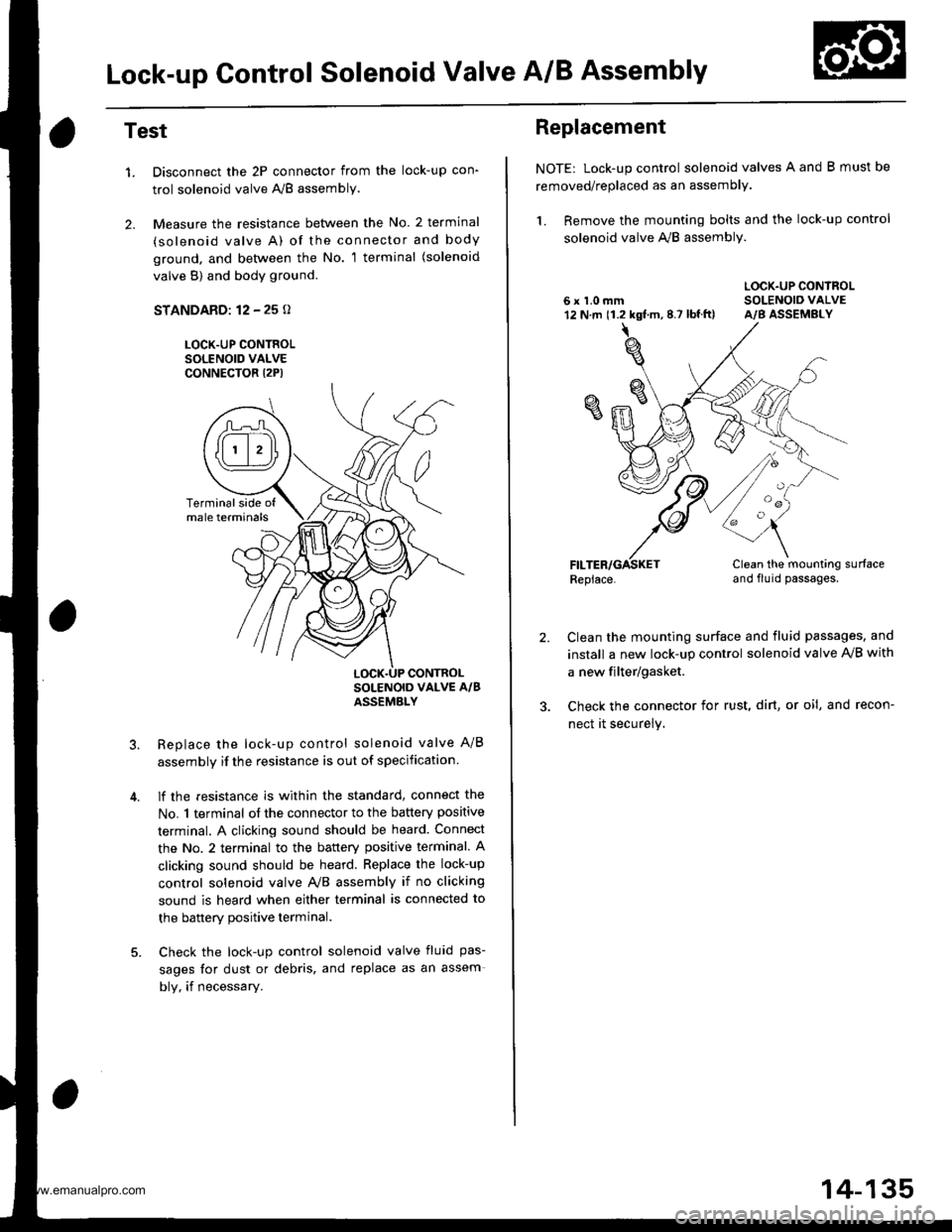
Disconnect the 2P connector from the lock-up con'
trol solenoid valve A'lB assembly.
Measure the resistance between the No. 2 terminal
(solenoid valve A) of the connector and body
ground. and bet\iveen the No. 1 terminal (solenoid
valve B) and body ground.
STANDARD: 12 - 25 o
LOCK-UP CONTROLSOLENOID VALVECONNECTOR I2P)
Replace the lock-up control solenoid valve A/B
assembly if the resistance is out of specification
lf the resistance is within the standard, connect the
No. 1 terminal of the connector to the battery positive
terminal. A clicking sound should be heard Connect
the No. 2 terminal to the battery positive terminal. A
clicking sound should be heard. Replace the lock-up
control solenoid valve Ay'B assembly if no clicking
sound is heard when either terminal is connected to
the banerv Dositive terminal.
Check the lock-up control solenoid valve fluid pas-
sages for dust or debris, and replace as an assem
bly, if necessary.
Terminalside ofmale terminals
LOCK.UP CONTROL
Replacement
NOTE: Lock-up control solenoid valves A and B must be
removed/replaced as an assembly.
1. Remove the mounting bolts and the lock-up control
solenoid valve A,,/B assembly.
LOCK.UP CONTROL6 x 1.0 mm SOLENOIO VALVE12 N.m 11.2 kgf.m,8.7 lbf.ft) A/B ASSEMBLY
Replace.Clean the mounting surfaceand flu id passages.
2.Clean the mounting surface and fluid passages, and
install a new lock-up control solenoid valve IVB with
a new filter/gasket.
Check the connector for rust, dirt, or oi!, and recon-
nect it securely.
oa
14-135
www.emanualpro.com
Page 652 of 1395
Shift Control Solenoid Valve A/B Assembly
Test
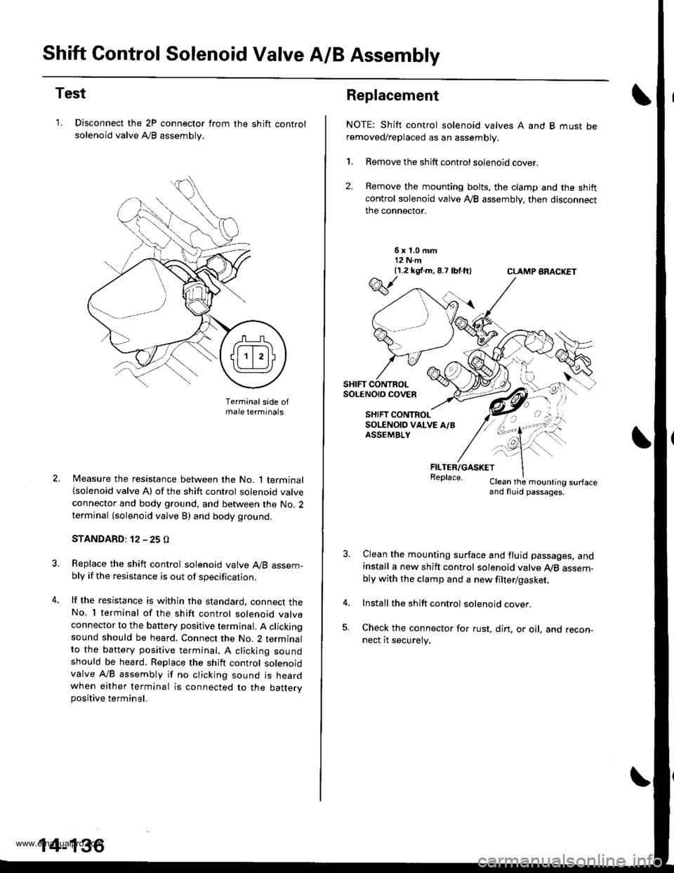
'1. Disconnect the 2P connector from
solenoid valve Ay'B assembly.
the shift control
Terminalsade ofmale terminals
Measure the resistance between the No. 1 terminal(solenoid valve A) of the shift control solenoid valve
connector and body ground, and between the No. 2terminal (solenoid valve B) and body ground.
STANDARD: 12 - 25 O
Replace the shift control solenoid valve A,/B assem-bly if the resistance is out of specification.
lf the resistance is within the standard. connect theNo, I terminal of the shift control solenoid valveconnector to the battery positive terminal. A clickingsound should be heard. Connect the No. 2 terminalto the battery positive te.minal. A clicking soundshould be heard. Replace the shift control solenoidvalve A/B assembly if no clicking sound is heardwhen either terminal is connected to the battervpositive terminal.
14-136
Replacement
NOTE: Shift control solenoid valves A and B must beremoved/replaced as an assembly.
1. Remove the shift control solenoid cover.
2. Remove the mounting bolts, the clamp and the shiftcontrol solenoid valve Ay'B assembly, then disconnect
the connector.
6x1.0mm12 N.m{1.2 k9 .m,8.7 lbtft}CLAMP ARACKET
FILTER/GASKETReplace.Clean the mounling surfaceand fluid passages.
Clean the mounting surface and fluid passages. andinstall a new shift control solenoid valve Ay'B assem-bly with the clamp and a new filter/gasket.
Install the shift control solenoid cover.
Check the connector for rust, dirt. or oil, and recon-nect it securely.
w
SHIFT CONTROLSoLENO|O COVEn
SHIFT CONTROLSOLENOID VALVE A/BASSEMBLY
\--
qK
-!t'">,,
www.emanualpro.com
Page 693 of 1395
![HONDA CR-V 1998 RD1-RD3 / 1.G Workshop Manual
r] REVERSE IDLER GEAR SHAFT/HOLDERA N€EDLE BEARING
..] TRANSMISSION HOUSING
al TRANSMISSION HOUSING OIL SEAL Replace.g SET BING.80 mm Selecrive part
O REVERSE GEAR COLLABE couNTERSHAFT REVERSE GEA HONDA CR-V 1998 RD1-RD3 / 1.G Workshop Manual
r] REVERSE IDLER GEAR SHAFT/HOLDERA N€EDLE BEARING
..] TRANSMISSION HOUSING
al TRANSMISSION HOUSING OIL SEAL Replace.g SET BING.80 mm Selecrive part
O REVERSE GEAR COLLABE couNTERSHAFT REVERSE GEA](/img/13/5778/w960_5778-692.png)
r] REVERSE IDLER GEAR SHAFT/HOLDER'A N€EDLE BEARING
..] TRANSMISSION HOUSING
al TRANSMISSION HOUSING OIL SEAL Replace.g SET BING.80 mm Selecrive part
O REVERSE GEAR COLLABE couNTERSHAFT REVERSE GEAB
.9,] NEEDLE BEARINGi9 LOCK WASHER Replace..1!i REVERSE SHIFT FORKO REVERSE SELECToRiJ. REVERSE SELECTOR HUBii' COUNTERSHAFT 4TH GEAR.14 NEEDLE BEARINGiD D|STANCE coLLAR,28 mm Selective part(i3 COUNTERSHAFT 2NO GEABi7-] THRUST NEEDLE BEARING(10 COUNTERSHAFT 3RD GEAR(9 NEEDLE BEARINGE9 COUNTERSHAFI3RD GEAB COLLAR.li THRUST NEEDLE BEARING.?) SPLINEO WASHER,,O 3RD CLUTCH ASSEMBLY
€1 O-RING Beplace.i23 COUNTERSHAFT
4i SHIFT CONTROL SOLENOID COVER
?Z] HARNESS CLAMP BRACKET
?9] SHIFT CONTROL SOLENOID VALVE A/B ASSEMBLY
8 HARNESS CLAMP BRACKET
GI SHIFT CONTROL SOLENOID VALVE FILTER/GASKET
(4 MAINSHAFT 2ND GEARi49 NEEDLE BEARING
@ THRUST NEEDLE BEARING(49 MAINSHAFT
@r SEAL|NG R|NG,35 mm
O SEALING RING,29 mm
@ NEEDLE BEARING
.49 SET RING
€) lST.HOLD CLUTCH ASSEMBLY
O o-RING Replace.6E THRUST WASHER
€9 THRUST NEEDLE BEARING
6' NEEDLE EEARING
€ir SUB-SHAFT 4TH GEAR
6 THRUST NEEDLE BEARING
@ SUB.SHAFT 4TH GEAR COLLAR@ sUB-sHAFf
6I NEEDI-E B€ARING STOP
@ NEEDLE BEARING(6t ATF GUIDE CAP Replace.(64 TRANSMISSION HANGEB
@ BREATHER CAP
i@ MAINSHAFT SPEED SENSOR
6i O-RING Replace.
6D REVERSE IDLER GEAR
@r DOWEL PlN, 14 x 25 mm.6d SNAP RINGS
QlI SUB.SHAFT TRANSMISSION HOUSING BEARING
E) MAINSHAFT TRANSMISSION HOUSING BEABING.2, COUNTERSHAFI TRANSMISSION HOUSINGBEARING
@[E
t,n9t0@)@),lD
04
@
@@:���������������.ro)
ai
Replace-SNAP RINGTHRUST WASHEBTHRUST NEEDLE BEARINGMAINSHAFT 4TH GEARNEEDLE BEARINGSTHRUST NEEDLE BEARINGMAINSHAFT 4TH GEAB COLLAR2NO/4TH CLUTCH ASSEMBLYO-RING Replace.THRUST WASHER,36.5 x 55 mm Selective partTHRUST NEEOLE BEARING
DOWEL PlN, 14 x 25 mmCONNECTOR BRACKETATF MAGNETDOWEL PlN, 14 x 20 mmTRANSMISSION HOUSING GASKET Replace.DIFFERENTIAL ASSEMBLYDOWEL PlN, 10 x 12 mmO-RING Replace.TRANSFER ASSEMBLYTOROUE CONVERTER HOUSING OIL SEAL Replace.TOROUE CONVERTER HOUSING
TOROUE SPECIFICATIONS
Bolt/Nut No.Torque ValueSizeRgmarks
6A
6B
10A
12 N.m (1.2 kgf.m,8.7 lbf.ft)
14 N.m (1.4 kgf.m, 10 lbift)
44 N.m (4.5 kgf.m,33 lbf.ft)
6x 1.0 mm
6x 1.0 mm
10 x 1.25 mm
14-177
www.emanualpro.com
Page 695 of 1395
oa;\,6
G)!o,
a@,6
@o(a
@(}
@a@@@@@@@6@@)@@@@@@@@@@@@@
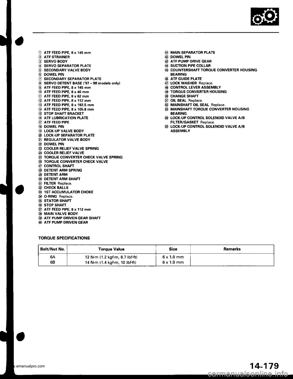
ATF FEED PIPE,8 x 145 mmATF STRAINERSERVO BODYSERVO SEPARATOR PLATESECONDARY VALVE EODYDOWEL PINSECONDARY SEPARATOR PLATESERVO DETENT BASE ('97 - 98 model3 onlylATF FEED PIP€, 8 x 145 mmATF FEED PIPE,8 x 40 mmATF FEED PIPE. 8 x 62 mmATF FEED PIPE.8 x 112 mmATF FEED PIPE, 8 x 192.5 mmATF FEEO PIPE. I x 105.8 mmSTOP SHAFT BRACKETATF LUBRICATION PLATEATF FEEO PIPEDOWEL PINLOCK-UP VALVE EODYLOCK-UP SEPARATOR PLATEREGULATOR VALVE BODYDOWEL PINCOOLER RELIEF VALVE SPRINGCOOLER RELIEF VALVETOROUE CONVERTER CHECK VALVE SPRINGTOROUE CONVERTER CHECK VALVECONTROL SHAFTOETENT ARM SPRINGOETENT ARMDETENT ARM SHAFTFILTER Replace.CHECK BALLSlST ACCUMULATOR CHOKEO"RING Replace.STATOR SHAFTSTOP SHAFTATF FEED PIPE, I x 112 mmMAIN VALVE BOOYATF PUMP DRIVEN GEAR SHAFTATF PUMP DRIVEN GEAR
TOROUE SPECIFICATIONS
MAIN SEPARATOR PLATEDOWEL PINATF PUMP DRIVE GEARSUCTION PIPE COLLARCOUNTERSHAFT TOROUE CONVERTER HOUSINGBEARINGATF GUIDE PLATELOCK WASHER Replace.CONTROL LEVER ASSEMBLYTOROUE CONVERTER HOUSINGCHANGE SHAFTOIL SEAL Reolace.MAINSHAFT OIL SEAL Reolace.MAINSHAFT TOROUE CONVERT€R HOUSINGBEARINGLOCK.UP CONTROL SOLENOID VALVE A/BFILTER/GASKET Replace.LOCK.UP CONTROL SOLENOID VALVE A/BASSEMBLY
@@@@@
@@@@@@@@
@
@
Bolt/Nut No.Torque ValugSizeRomarks
64
6B
12 N'm (1.2 kgf.m,8.7 lbf.ft)
14 N.m (1.4 kgf.m, 10 lbf.ft)
6x1.0mm
6x1.0mm
14-179
www.emanualpro.com
Page 699 of 1395
oatl,6
@!.,
ao6l
@o@@@@@o@@@)@@@@@@@@@@)
@@@@)@@@@@@@
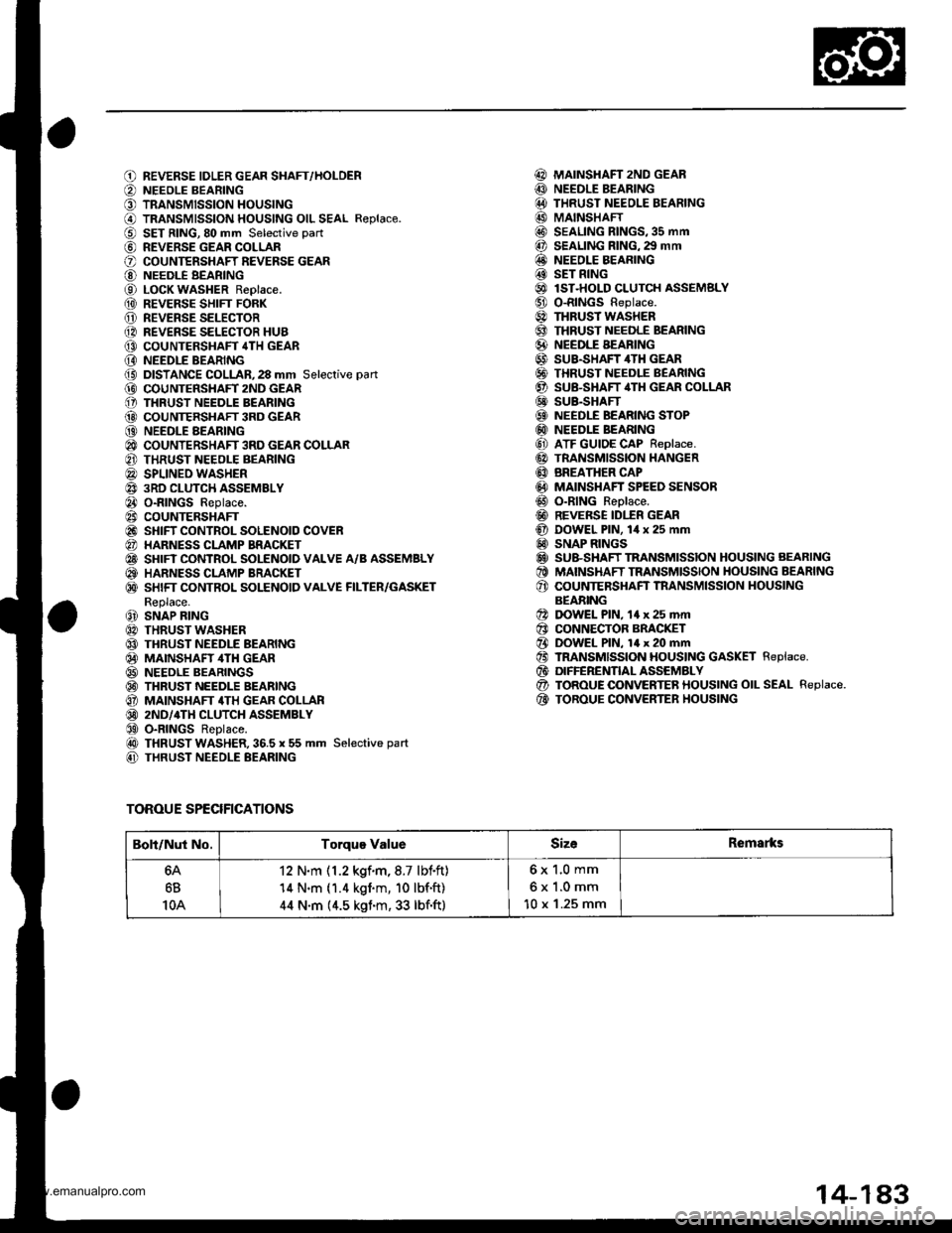
REVERSE IDLER GEAR SHAFT,/HOLDERNEEOLE BEARINGTRANSMISSION HOUSINGTRANSMISSION HOUSING OIL SEAL R€place.SET RING,80 mm Selective part
REVERSE GEAR COLLARCOUNTERSHAFT REVERSE GEARNEEDLE BEARINGLOCK WASHER Replace.REVERSE SHIFT FORKREVERSE SELECTORREVERSE SELECTOR HUBCOUNTERSHAFT 4TH GEARNEEDLE BEARINGDISTANCE COLLAR,28 mm Selective pan
COUNTERSIIAFT 2ND GEARTHRUST NEEDLE BEARINGCOUNTERSHAFT 3RD GEARNEEDLE AEARINGCOUNTERSHAFT 3RD GEAR COLLARTHRUST NEEOLE BEARINGSPLINEO WASHER3RD CLUTCH ASSEMBLYO-RINGS Replace.COUNTERSHAFTSHIFT CONTROL SOLENOID COVERHARNESS CLAMP BRACKETSHIFT CONTROL SOLENOID VALVE A/B ASSEMBLYHARNESS CLAMP BRACKETSHIFT CONTROL SOLENOID VALVE FILTER/GASKETReplace.SNAP RINGTHRUST WASHERTHRUST NEEDLE BEARINGMAINSHAF ,ITH GEARNEEDLE BEARINGSTHRUST NEEDLE BEARINGMAINSHAFT 4TH GEAR COLLAR2ND/4TH CLUTCH ASSEMBLYO-RINGS ReDlace.THRUST WASHER,36.5 x 55 mm Selective part
THRUST NEEDLE BEARING
MAINSHAFT 2ND GEARNEEDLE BEARINGTHRUST NEEOLE BEARINGMAINSHAFTSEALING RINGS,35 mmSEALING RING. 29 mmNEEDLE BEARINGSET RINGlST-HOLD CLUTCH ASSEMSLYO-RINGS Replace.THRUST WASHERTHRUST NEEDLE BEARINGNEEDLE BEARINGSUB.SHAFT 4TH GEARTHRUST NEEDLE BEARINGSU&SHAFT,ITH GEAR COLLARSUB.SHAFTNEEDLE BEARING STOPNEEDLE BEARINGATF GUIDE CAP Replace.TRANSMISSION HANGERBREATHER CAPMAINSHAFT SPEED SENSORO-RING Reolace.REVERSE IDI.fR GEARDOWEL PlN, lil x 25 mmSNAP RINGSSU&SHAFT TRANSMISSION HOUSING AEARINGMAINSHAFT TRANSMISSION HOUSING BEARINGCOUNTERSHAFT TNANSMISSION HOUSINGBEABINGDOWEL PlN, 14 x 25 mrnCONNECTOR BRACKETDOWEL PlN, 14 x 20 mmTRANSMISSION HOUSING GASKET Replace.DIFFERENTIAL ASSEMBLYTOROUE OONVERTER HOUSING OIL SEAL Replace.TOROUE CONVERTER HOUSING
@@@@@@@@@@@@@@@@@@@@@@@)@@@@@@@
@@@@@@@
TOROUE SPECIFICATIONS
Boli/Nut No.Torque ValueSizeRemarks
6B
10A
12 N.m (1.2 kgf.m,8.7 lbf.ft)'14 N.m (1.4 kgim, 10 lbf'ft)
44 N.m (4.5 kgim, 33 lbf.ft)
6x 1.0 mm
6x1.0mm
10 x '1.25 mm
14-1A3
www.emanualpro.com
Page 1139 of 1395
}-Overhaul
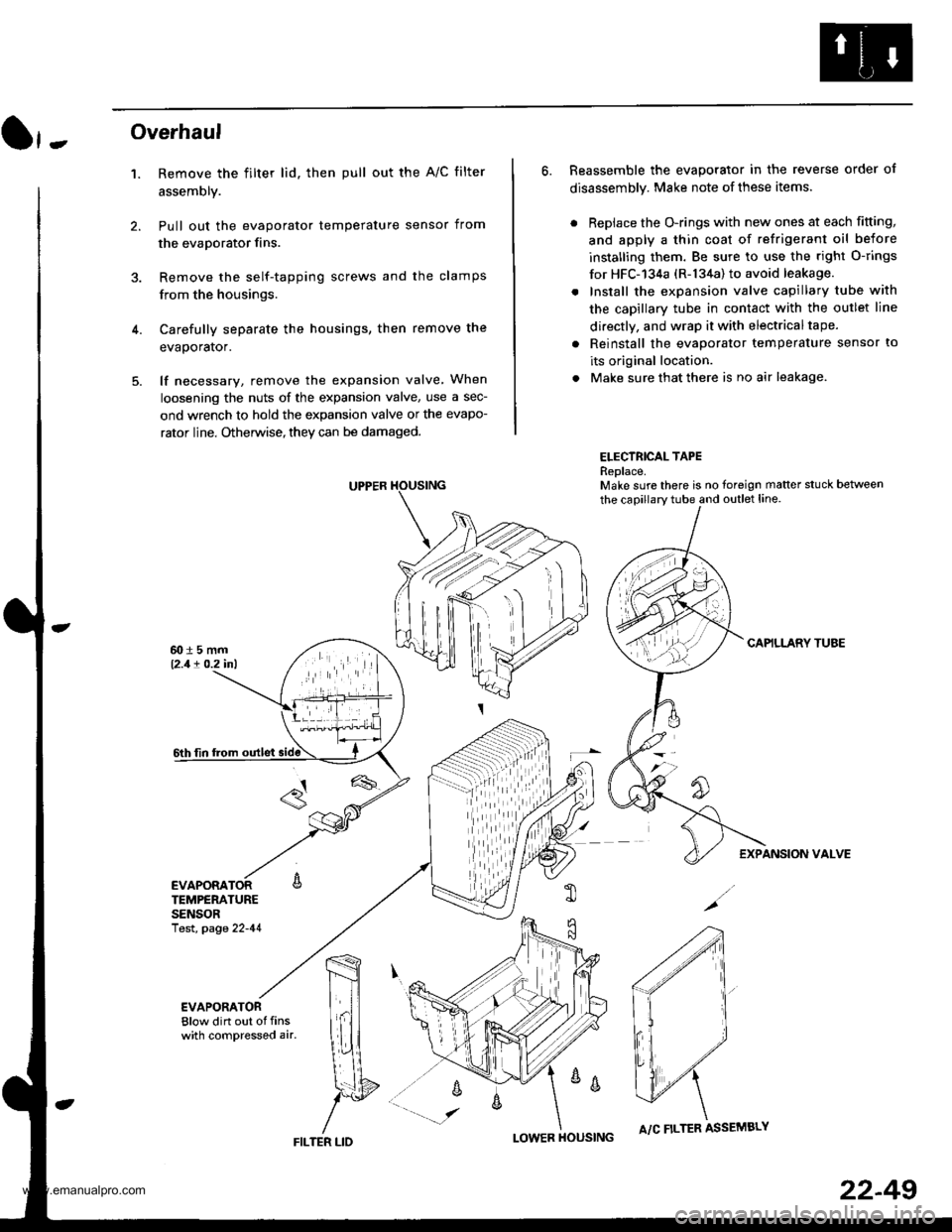
1. Remove the filter lid. then pull out the A/C filter
assembly.
Pull out the evaporator temperature sensor from
the evaporator fins.
Remove the self-tapping screws and the clamps
from the housings.
Carefully separate the housings, then remove the
evaporator.
lf necessary, remove the expansion valve When
loosening the nuts of the expansion valve, use a sec-
ond wrench to hold the expansion valve or the evapo-
rator line. Otherwise, they can be damaged.
6. Reassemble the evaporator in the reverse order of
disassembly. Make note of these items.
. Replace the O-rings with new ones at each fitting,
and apply a thin coat of refrigerant oil before
installing them. Be sure to use the right O-rings
for HFC-'134a (R-134a) to avoid leakage.
. Install the expansion valve capillary tube with
the capillary tube in contact with the outlet line
directly, and wrap it with electricaltape.
. Reinstall the evaporator temperature sensor to
its original location.
. Make sure that there is no air leakage.
ELECTRICAL TAPEReplace.Make sure there is no foreign matter stuck between
the capillary tube and outlet line.
CAPILLARY TUAE
EXPANSION VALVE
4.
TEMPERATURESENSORlest, page 22-41
,m
\!{
YFILTER LID
;
I-OWER HOUSINGA/C FILTER ASSEMBLY
22-49
www.emanualpro.com
Page 1140 of 1395
A/C FilterHeater Unit
Replacement
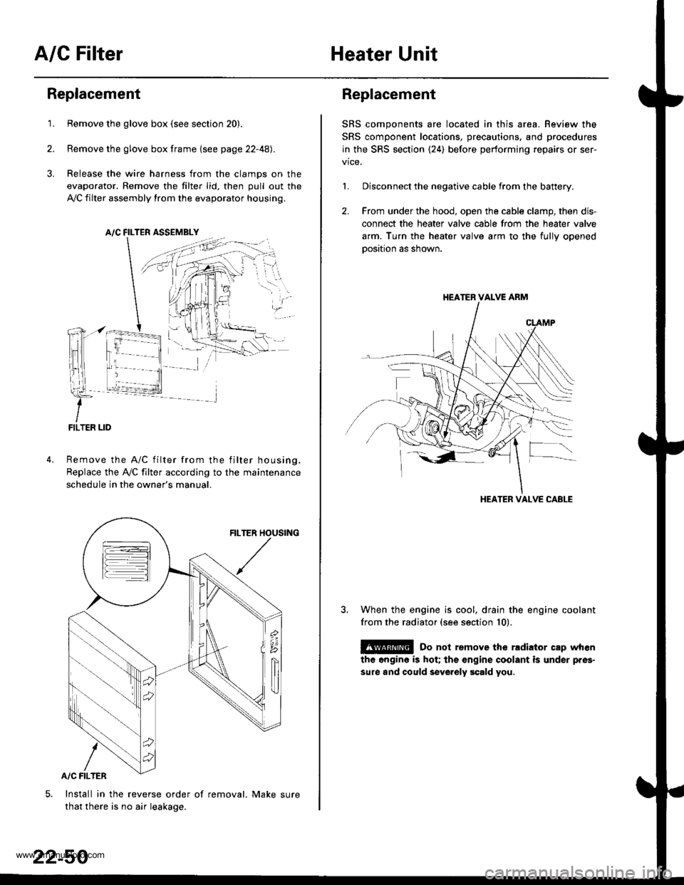
1.Remove the glove box (see section 20).
Remove the glove box frame {see page 22-4A).
Release the wire harness from the clamps on the
evaporator. Remove the filter lid, then pull out the
,VC filter assembly from the evaporator housing.
A/C FILTER ASSEMELY
Remove the A/C filter from the filter housing.
Replace the Ay'C filter according to the maintenance
schedule in the owner's manual.
Install in the reverse order of removal. Make sure
that there is no air leakage.
22-50
Replacement
SRS components are located in this area. Review the
SRS component locations, precautions, and procedures
in the SRS section {24) before performing repairs or ser-
1. Disconnect the negative cable from the battery.
2. From under the hood, open the cable clamp, then dis-
connect the heater valve cable from the heater valve
arm. Turn the heater valve arm to the fullv ooened
oosition as shown.
When the engine is cool, drain the engine coolant
from the radiator (see section 10).
@ Do not remove the rldiator cap when
the engine is hot; the engine coolant is under pres-
sure and could sevo.ely scald you.
HEATER VALVE ARM
HEATER VALVE CABLE
www.emanualpro.com