Under hood HONDA CR-V 1998 RD1-RD3 / 1.G Workshop Manual
[x] Cancel search | Manufacturer: HONDA, Model Year: 1998, Model line: CR-V, Model: HONDA CR-V 1998 RD1-RD3 / 1.GPages: 1395, PDF Size: 35.62 MB
Page 3 of 1395
General lnformation
Chassis and Paint Codes ....................... 1-2
ldentification Number Locations ......... 1-10
Warning/Caution Label Locations ....... 1-11
Under-hood Emissions Control
Label .......... ..................... 1-15
Lift and Support Points
Lift and Safety Stands ....................... 1-19
Floor Jack ....................... 1-20
Towing .........1-21
Service Precautions
Pafts Marking Locations ..,................. 1-22
Precautions for Real-time 4WD
(Four-wheel Drivel ......... ................. 1 -23
www.emanualpro.com
Page 16 of 1395
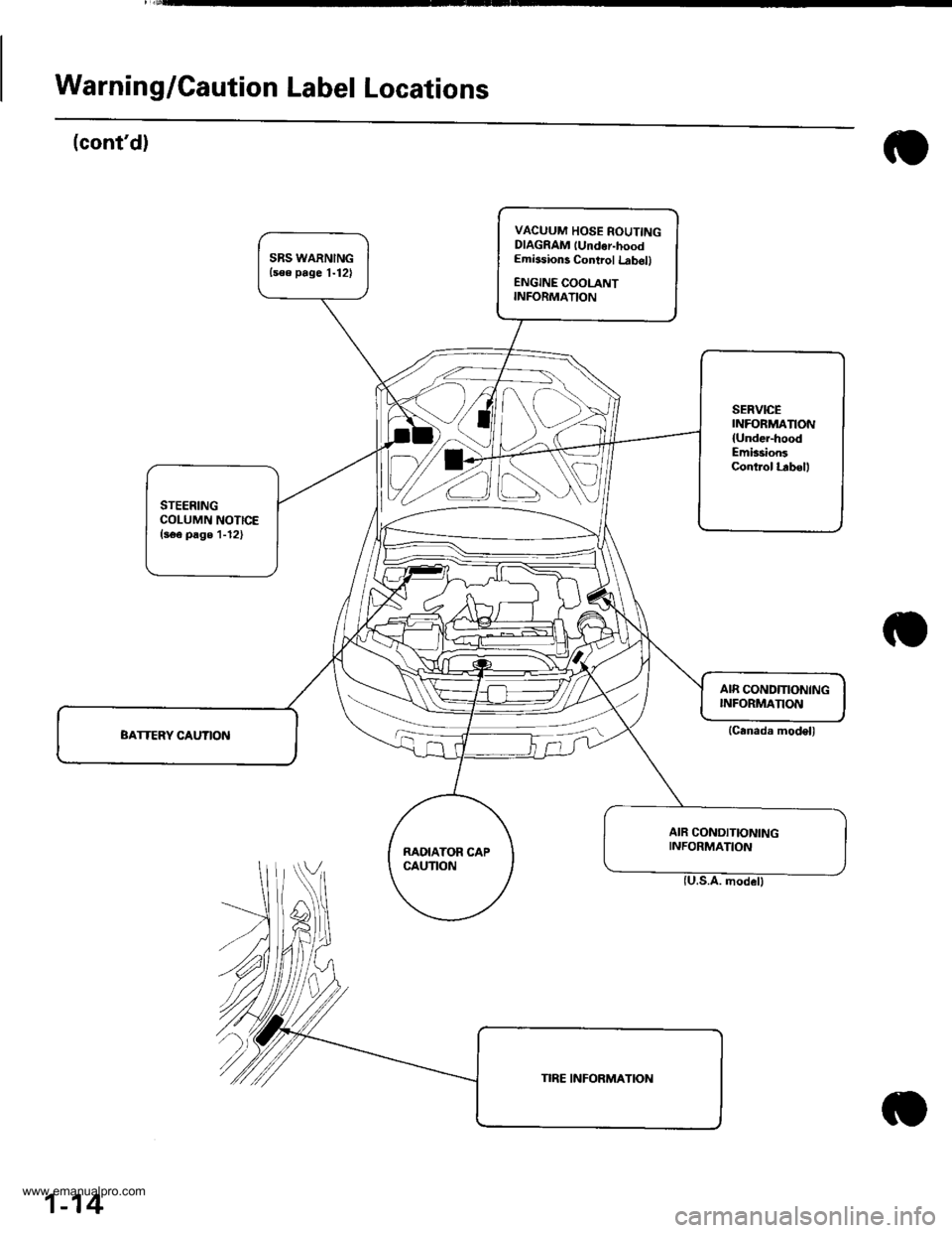
Warning/Caution Label Locations
(cont'd)
VACUUM HOSE ROUTINGDIAGRAM lUndor-hoodEmissions Control Lrb6ll
ENGINE COOLANTINFORMATION
SERVICEINFORMANON
{Under-hoodEmission3Control l.rbell
STEERINGCOLUMN NOTICE(s€e page 1-12)
RAOIATOR CAPCAUTION
AIR CONDITIONINGINFORMATION
(Canada model)
1-14
www.emanualpro.com
Page 17 of 1395
![HONDA CR-V 1998 RD1-RD3 / 1.G Workshop Manual
Under-hood Emissions Control Label
Emission Group ldentification
(1997 modell
Example:
VACUUM HOSE ROUTING DIAGRAM
LOADED IM TEST]NG OF PERMANENT fOUB WHEEL OSVE OR TRACT ON CONTROLEOLJIPPEDVEHTCLES HONDA CR-V 1998 RD1-RD3 / 1.G Workshop Manual
Under-hood Emissions Control Label
Emission Group ldentification
(1997 modell
Example:
VACUUM HOSE ROUTING DIAGRAM
LOADED IM TEST]NG OF PERMANENT fOUB WHEEL OSVE OR TRACT ON CONTROLEOLJIPPEDVEHTCLES](/img/13/5778/w960_5778-16.png)
Under-hood Emissions Control Label
Emission Group ldentification
(1997 modell
Example:
VACUUM HOSE ROUTING DIAGRAM
LOADED IM TEST]NG OF PERMANENT fOUB WHEEL OSVE OR TRACT ON CONTROL'EOLJIPPEDVEHTCLES MUST BE CONDUCTED ON A IOUR WHEEL DR VE SPEEO SYNCHRON ZED
ANON LOADEDTESTPBO(EOUBEMUSIBEPERFORMEO
50ST (50 Statesl:
THIS VEHICLE CONFOBMS TO U.S. EPA AND STATE OF
CALIFORNIA REGULATIONS APPLICABLE TO 1997
MODEL YEAR NEW LIGHT DUTY TRUCKS.
49ST {49 Statos/Federall:
THIS VEHICLE CONFORMS TO U.S. EPA REGULATIONS
APPLICABLE TO 1997 IVIODEL YEAR NEW LIGHT DUTY
TRUCKS.
CAL (Calitornial:
THIS VEHICLE CONFORMS TO U.S. EPA AND STATE OF
CALIFORN IA REGULATIONS APPLICABLE TO '1997
MODEL YEAR NEW TLEV LIGHT DUTY TRUCKS
PROVIDED THAT THIS VEHICLE IS ONLY INTRODUCED
INTO COMMERCE FOR SALE IN THE STATE OF
CALIFORNIA.
Ii/PORTANT VEHICLE INFORIMATIONENGINE FAMILY VHN2 OIJCrcKDISPIACEMENT'2 OLITEREVAPORAT VE f AM]LY VNNl0778YMBP
CATALYSTREfERTOSEBVICEMANUALfORAODITIONAL NFORMATON.TUNT I-]P CONDITIONSENGINE AT NORI\,!AL OPERATNG TEMPERATURE,ALLACCESSOR ES TL]RNED OFF COOLING FAN OIFTRANSM1SSION NNEUTRALNO OTHEB ADJUSTMENIS NEEDED
ap' | \6( Zror '. ND \. 61F L r
TNIS VENICLE CONFORMS TO U.S EPA REGUI.ATIONSAPPI CASLE TO I99] MODET YEAR N€W L GNI DUTY TRACKS
@
Engine Family: vHN2.o l JGKE
Engine and Evaporative Families
T_fT
Model Year I Iv:1s97 | LManufaqturer iHN: Honda I
Displacement
Class
1: Light Duty Vehicle
Fuol Systom ,nd Numb€r of valves
J: Electronic Sequential Multiport
Injection (three or more valves per
cylinder)
Fuel Type
G: Gasoline
Standard
F: 49 or 50 States Tier 1
K: 49 or 50 States Tier 1
1: California Tier 1
2: California TLEV
3: California LEV
4: California ULEV
"r0", "*,
T|
V: 1997
Manufacturer
HN: Honda
Catalyst
E, F, G, H: Three Way Catalyst
OBD
K - T: OBD Equipped
Evaporative Family:
Storago System
1: Canister
Canistor Working Capacity (gramsl
Canister Conf igulation
A: Plastic Housing (Closed Bottom)
B: Plastic Housing (OPen Bottom)
Fusl System
Y: Fuel Injection
FuelTank
M: Metal
Standard
A: Current Evap
B: Enhanced Evap
Wild C.rd
VHNlOTTBYMBP
1-1 5
www.emanualpro.com
Page 18 of 1395
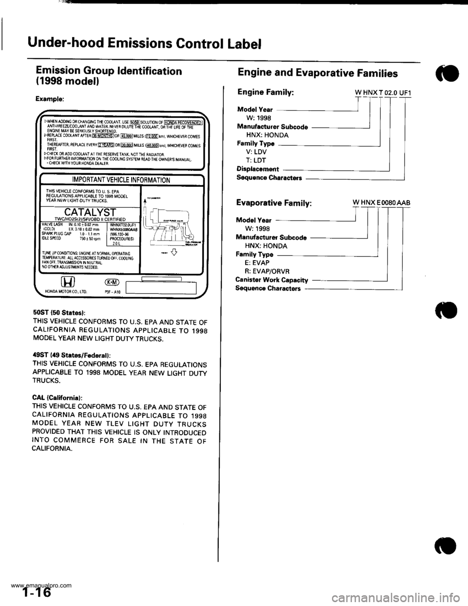
Under-hood Emissions Control Label
Emission Group ldentification
(1998 modell
Example:
50ST {50 States}:
THIS VEHICLE CONFORMS TO U.S. EPA AND STATE OFCALIFORNIA REGULATIONS APPLICABLE TO 1998MODEL YEAR NEW LIGHT DUTY TRUCKS,
/$ST (itg Statos/Fodsrsll:
THIS VEHICLE CONFORMS TO U.S. EPA REGULATIONSAPPLICABLE TO 1998 MODEL YEAR NEW LIGHT DUTYTRUCKS.
CAL {California}:
THIS VEHICLE CONFORMS TO U.S. EPA AND STATE OFCALIFORNIA REGULATTONS APPLICABLE TO 1998MODEL YEAR NEW TLEV LIGHT DUTY TRUCKSPROVIDED THAT THIS VEHICLE IS ONLY INTRODUCEDINTO COMMERCE FOR SALE IN THE STATE OFCALIFORNIA.
DwlF AIo|NG oB cha\Gtftc I + coot r
-s€ msoru1or or FoNoA-IEaoTTxD-ibl1'v! Lrff EzEcoo-aN' a\D wATfB. M w r or_ut-ir coolqNt, oR-l;ir,FEaFEf-ENGINE MAY BE SEflIOUSLYSIONTENEO.DSEPLACI CoOTANT AnEs 85 itNlgsloF @ MILIS l@0 rnl, wHrcHEvEs coMEs
TNEREAFT€R, REPLACE EvEny fmAFSl m m M[Es i@ kml, wHcHrvEB coMEs
DCHEC(ONADOCOOLqNTATTHE RSSEFVETANX. NOTTHE iAD]ATOR.DFOR FUFTNEfr INFO8MATION ON IN€ COOT]NC SYSIEM NEAD THE OWNEN'S MANUAL,. CHECK W|TH YOUR NONDA OEALEF.
@GD
IMPORTANT VEHICLE INFORMATION
THIS VEHICLE CONFOEMS TO I], S. EPAFEGIJLAIIONSAPPLICASLE TO 1993 MOOELY€AF NEW LIGHT DUIYTNUCXS.
CATALYSTrwqHozst2l/sFt/osD l cERI|FtEOvAlvttAsH lrr0.l010.02nmicolo) EX:01310.02mmSPAS( PIUG GAP I.O IINMlDLl SPTED 750 I 50 rym686,13G96PROCEOURESI2.0 L
TlNt UPCoND/ToNS: ENGINE AT NOiMIEMPETAIURT,ALLACCESSORIESTUNNIfAN OFf. TRAI1SMISSON IN NEUTMINO OIIIER AOJUSTI\TFIIS IIEEOED.
1-16
Engine and Evaporative Families
Engine Family:W HNX T O2.O UF1
Mod€l Year
W: 1998
Manufacturer Subcods
HNX: HONDA
Family Typo
V: LDV
T: LDT
Displacomsnt
Soqu€nco Characiors
Evaporative Fami
Family:
Model Yeat
W:1998
Manufastu16r Subcode
HNX: HONDA
Family Type
E: EVAP
R; EVAP/ORVR
Canister Work Capacity
Sgquonco Charaqtsrs
W HNX EOOSOAAB
www.emanualpro.com
Page 20 of 1395
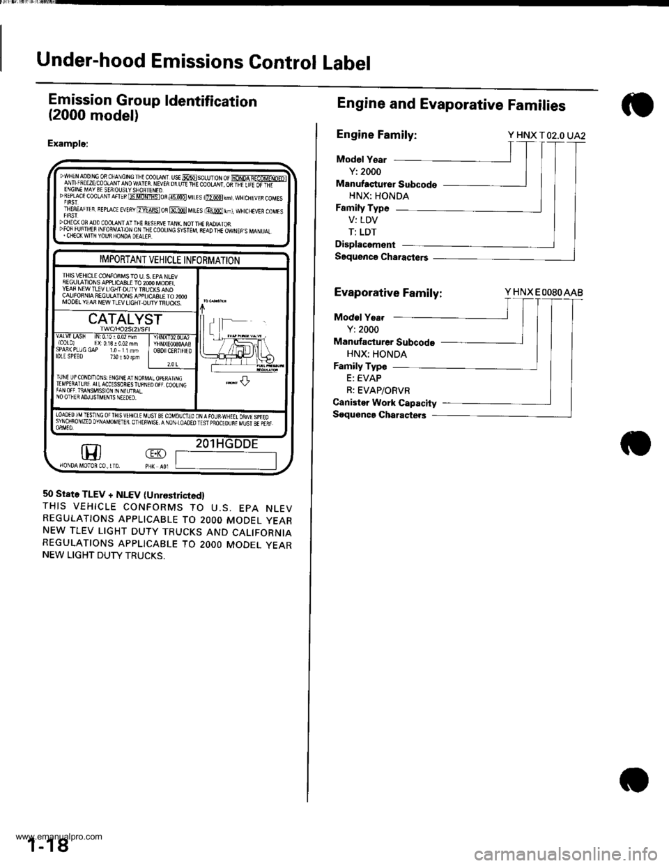
Under-hood Emissions Control Label
Emission Group ldentification
(2000 model)
Example:
DWFEN aDD r,tc 0R ChA\CtN! rlt cooraN. ust MsoLU- oN or fioNpA q-af6MrNp-ol
lfi ;!,."5:P!$t:1t9ffilf 1
vEn u u'r +-E coo|-d',r os-Fiiiiifi-'DREpf cE coolaNrAFTEBt3tlomistoR@MtLEs r@km),wH ctlEvrscoMEsT|E8EAFTER, BEprAcE EVEny ErdFst oB @ MttEs lmr,t, ffitcHEVER coMEsDCIIICX OF ADD COOLA I I'-FE AISIRVI TAI{I\. NOI THE MDIAIOR":3lliJ#fl "lj,9lx6L;T&Iji(0or|]\G s,5TEM 8r!D TrE owrEp s MA\u.r.
m
IMPORTANT VEHICLE INFORMATION
IHIS \/IHICLE CONFONMS TO U. S. EPA NLEVSEGULATIONS APPIJCq3LE TO 2OOO IVOOELYEAF NEW T!!V LIGHT DUTY TBUCKS ANDCALIFONNIA SEGULATIONS APPLICASLE TO 2OOOMOO€L YIAA NEW TLEV LIGHT.OUTY TFIJCKS.
CATALYST
vALvt LA5h tN:0,10r0.02 mm{C0t0l El:0.13!002 mhSPAn(PLUGGAP 1.0-11mmlDlE SPEEo 734150lpmO8O CENTFIED
?.0 t
TUNI UP CoNDIToNS: ENGINE AT NORMTTMPERAIURE ATLACCESSORIES fu BNITAN OFF TiANSMISS ON IN N€UTRALNO OTHER AD.ILJSTMENIS NEEDEO.
.l-L
|oAoEDr/MTESTNG oFTHsvtHrctE uLrst gt couolorooN,{raua.wxEtt onuspreosyNoiRoN zEo DvNAMoMETER. olrEiwsE. A NoN.LoAoEo rEsr pBocEounr uust sr pair
1
50 State TLEV + NLEV (Unrestricied,
THIS VEHICLE CONFORMS TO U.S. EPA NLEVREGULATIONS APPLICABLE TO 2OOO MODEL YEARNEW TLEV LIGHT DUTY TRUCKS AND CALIFORNIAREGULATIONS APPLICABLE TO 2OOO MODEL YEARNEW LIGHT DUTY TRUCKS.
1-18
Engine and Evaporative Families
Engine Family:Y HNX TO2.O UA2
Model Y€ar
Y: 2000
Manufaqturer Subcodo
HNX: HONDA
Family Type
V: LDV
T: LDT
Displacement
Saquenco Charasters
Evaporative Family:Y HNX EOOSOAAB
Modol Yea.
Y: 2000
Manufacturer Subcode
HNX: HONDA
Family Type
E: EVAP
R: EVAP/ORVR
Canister Work Capacity
Soquenca Charactet3
www.emanualpro.com
Page 38 of 1395

--
-
METRICITEMENGLISHNOTES
AIR CONDITIONINGCooling capacity3,520 Kcal/h j 14,000 BTU/h
Compressor Type/manutacturerNo. of cylinderCaPacityMax. speedLubricant capacityLubricant type
Scroll/KElHlN
85.7 mf/rev | 5.23 cu'in/rev10,000 rpm130mf 1 algIlozsP-10
Condenser TypeCorrugated fin
Evaporator TypeCorrugated fin
Blower TypeMotor inputSpeed controlMax. capacity
Sirocco fan200 w 112 v4-Speeo440 m3/h 15,500 cu fvh
Temperature control
Compressor clutch TypePower consumptionDry, single plate, poly-V-belt drive40 W max./12 VAt 68'F (20 C)
Befrigerant TypeOuantity
HFC-134a 1R-134a)zoo o' g 24j an oz
STEERING SYSTEMTypeOverall ratioTurns, lock to lockSteering wheel diameter
Power assisted, rack and pinion
SUSPENSIONType Front
Bear
Shock absorber Front and Rear
Independent double wishbone, coil springwith stabilizerIndependent double wishbone, coil springwith stabilizerTelescopic, hydraulic nitrogen gas tilled
WHEEL ALIGNMENTCamber
CasterTotaltoe
FronthearFrontFrontRear0inln 1/16 in0mmln2mm
0'- r"00'2.10'�
BRAKE SYSTEMTvpe
Pad surface areaLining surface areaParking brake
Front
RearFrontRearTvpe
Power-assisted selt-ad,ustingventilated discPower assisted self-adiusting drum49 cm, x 2 7.6 sq-in x 273 cm, x2 11.3 sq-in x 2Mechanical actuating, rear two wheel brakes
Drum brake
TIRESize and pressureSee tire inlormation label.
ELECTRICALBafteryStarterAlternator
In under-dash fuse/relay boxIn under hood fuse/relay box
In underhood ABS fuse/relay boxHeadlightsFront turn signal lights
Front parking lightsFront side marker lightsRear side marker lightsRear turn signal lightsErake/parking lightsBack-up lightsCeiling lights {fronvrear)License plate lightSpotlightsHigh mount brake lightlgnition key lightAshtray lightGauge lightsIndicator lightslllLrmination and pilot IightsHeater illumination lights
12 V, 36 AH/s HR12V 1.0, 1.1 kW12V 100A
7.5 A, 10 A, 15 A, 20 A7.5 A, 10 A, 15 A, 20 A, 30 A, 40 A'100 A7.5 4,20 A. 40 A12V 60/55 W12 V- 21 W ('97 model),12 V - 27 W ('98-00 models)12V 5 W {'97 model),3 CP ('98 - 00 models)12V-8W12 V,3 CP12V-21W12 V 2115 W12V 21 CP (18 W)12V-8W12V-8W12V-5W12V -21W
12 V- 1.4 W12V 1.4 W12 V 1.4 W,3 W,3.4 W12V-0.84W, 1.12 W, 1.4 W,3 W, LED12 V - 0.84 W, 1.4 W, LED12 V,1.4 W
2-13
www.emanualpro.com
Page 54 of 1395
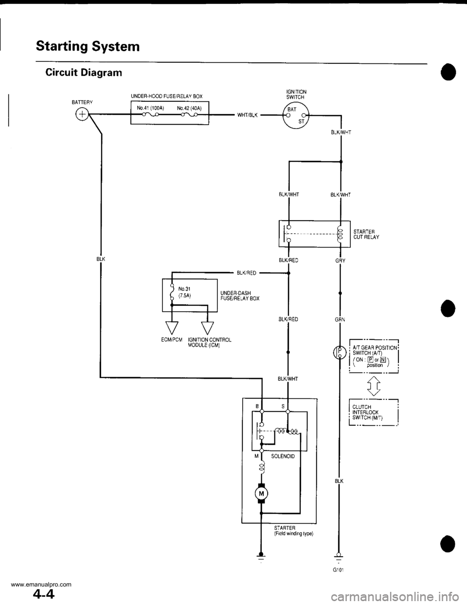
Starting System
Circuit Diagram
IGN TIONSWITCH
/ BAI \-+o cf-.|
\i7 IBLKMHT
II
I
tl
tlELKMHT BLK'WHT
STARTEFCUl RELAY
I A/T GEAR PosrroN!i swrTcH (A/T) |l/oN EorN |l p.siton / :!-- -_ --___J
f';--"-lI TNTERLooK I
fYl""yl, I
GRY
IGRN
8LK
Gl0l
UNDER.HOOD FUSE/RELAY 8OX
N0.41 (100A) N0.42 (40A)
-.1
BLKRED
I
IGNITION CONTROLMOoULE ( CM)
STARTEB(Field wnd ng lype)
4-4
www.emanualpro.com
Page 55 of 1395

Starting System
Starter Test
NOTE: The air temperature must be between 59 and'100'F (15 and 38"C) before testing.
Recommended Procedure:
. Use a staner system tester.
. Connect and operate the equipment in accordance
with the manufacturer's instructions.
. Test and troubleshoot as described.
Alte.nate Procedure:
. Use the following equipment:- Ammeter, 0 - 400 A- Voltmeter, 0 - 20 V (accurate within 0.1 volt)
Tachometer,0 - 1,200 rpm
. Hook up a voltmeter and ammeter as shown.
NOTE: After this test, or any subsequent repair. reset
the ECM/PCM to clear any codes (see section 1 1).
Check the Starter Engagement:
'1. Remove the No. 44 (15 A) fuse from the under-hood
fuse/relay box.
2. Turn the ignition switch to START (lll) with the shift
lever in E or E position (A/T) or with the clutch
pedal depressed {M/T). The starter should crank the
eng ine.
. lf the starter does not crank the engine, go to
step 3.
. lf it cranks the engine erratically or too slowly, go
to "Check for Wear and Damage" on the next
page.
NEGATIVE TERMINAL
4.
5.
6.
7.
8.
Check the battery, battery positive cable, ground.
staner cut relay, and the wire connections for loose-
ness and corrosion. Test again.
lf the staner still does not crank the engine, go to
step 4.
Unplug the connector (BLK /VHT wire and solenoid
terminal) from the starter.
Connect a jumper wire from the baftery positive (+)
terminal to the solenoid terminal.
The starter should crank the engine.
. lf the starter still does not crank the engine,
remove it, and diagnose its internal problem.
. lf the starter cranks the engine, go to step 6.
Check the ignition switch (see section 23).
Check the starter cut relay {see section 23}.
Check the IVT gear position switch (A/T) or the clutch
interlock switch (M[).
Check for an open in the wire between the ignition
switch and starter.
(cont'd)
4-5
www.emanualpro.com
Page 87 of 1395
UNDER.OASH FUSARELAY BOX
INDICATORLIGHT(0.84W)
lPIOSET
526712813
CRUISE CONTROT UNLT 10
11114
COMEINATONL GH'I SWITCH
f7
IRED/BLK
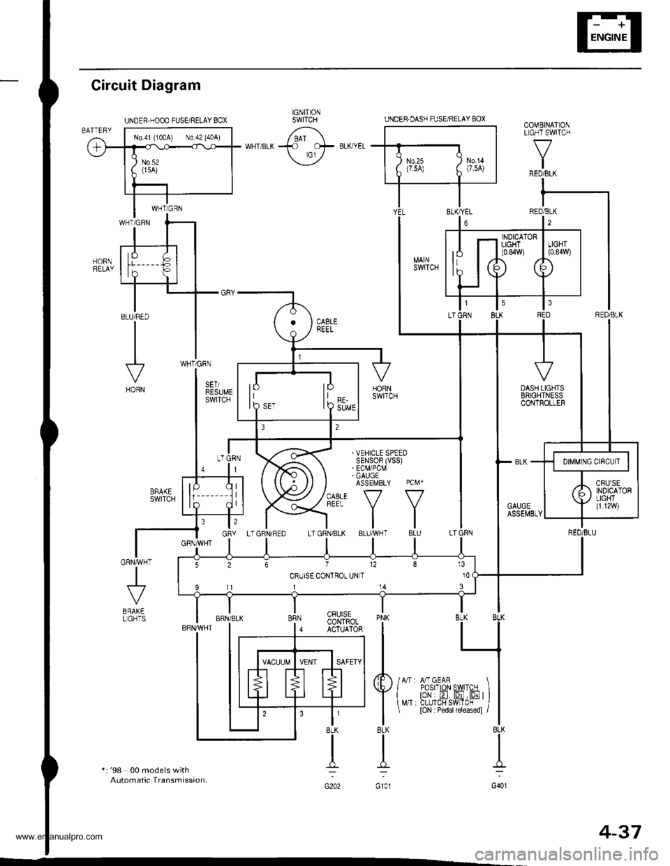
Gircuit Diagram
*: '98 00 models withAutomatic Transmission.
J
BRAK€LGHTSPNK BLK BLK
I L_l
tl
4F /lr,mcern I I
Y{"^ i?tr'.flffi'JF ) l
I
t loN : Pedar rereasedl /l
8LK BLK
TI
G101 G401
CRUISECONTROLACTUATOR
t'BLK
n:
G202
IGNIT ONSWITCHUNDER.HOOD FUSEi RELAY BOX
No 41 (100A) No 42 (404)
4-37
www.emanualpro.com
Page 89 of 1395

Disconnest the lilP connector from the control unit.
Csvity WireTest condition
R€conn€ct tho 14P connGctor to the control unit.
Test: Desired resultPossible cause it result is not obtained
BRNAr'VHTUnder all conditionsCheck for resistance to groundl
There should be 80 - 120 o.
Faulty actuator solenoid
Poor ground (G202)
An open in the wire1BRNUnder all conditionsCheck for resistance to groundl
There should be 40 - 60 0.
11BRN/BLKUnder all conditionsCheck for resistance to ground:
There should be 70 - 110 O.
2GRY
lgnition switch ON (ll),
main switch ON and
brake pedal depressed,
then released
Check for voltage to ground:
There should be 0 V with the pedal
depressed and battery voltage with
the pedal released.
. Faulty brake switch. An open in the wire
BLKUnder all conditionsCheck for continuity to ground:
There should be continuity.
. Poor ground (G401). An open in the wire
5GRNMHT
Brake pedal depressed,
then released
Check for voltage to ground:
There should be battery voltage with
the pedal depressed, and 0 V with
the pedal released.
Blown No.52 1'15 Alfuse in the
under-hood fuse/relay box
Faulty brake switch
An open in the wire
LT GRN/
RED
Set button pushedCheck for voltage to ground:
There should be battery voltage.Blown No. 52 {'15 A} fuse in the
under-hood fuse/relay box
Faulty horn relay
Faulty sevresume switch
Faulty cable reel
An open in the wire7LT GRN/
BLK
Resume button pushed
10RED/BLU
lgnition switch ON lll)Attach to ground:
Cruise indicator light in the gauge
assembly should come on.
Elown bulbBlown No. 25 (7.5 A) tuse in theunder-dash fuse/relay box
Faulty dimming circuit in the gauge
assembly
An open in the wire
ELU^r'r'HT
lgnitjon switch ON {ll}and main switch ON;
raise the front of the
vehicle, block one wheel
and rotate the other
wheel slowly.
Check for voltage between the
ELUA/VHT @ and BLK O terminalsl
There should be 0 - 5 V or more-0 - 5 V or more repeatedly.
Faulty vehicle speed sensor (VSS)
An open in the wire
r3LT GRN
lgnition switch ON {ll}and main switch ONCheck for voltage to ground:
There should be battery voltage.
Blown No. 14 (7.5 A) fuse in theunder-dash fuse/relay box
Faulty main switch
An open in the wire
l4PNK
A'/T: Shift lever in E, EotE
lvl/T: Clutch pedal
releaseo
Check for continuity to ground:
There should be continuity.NOTE: There should be no continu-
ity when the shift lever is in otherpositions or when the clutch pedal is
oepresseo.
Faulty A/f gear position switch 1A,/TlFaulty or misadjusted clutch switch
fi{/r)Poor ground (G101)
An open in the wire
BLU
Start tho engine. turnthe main switch ON, anddrive the vehicle over 25
mph (40 km/h)with the
crurse control set
Check for voltage to ground:
There should be approx.5 V
. Faulty cruise control unit. Shod to ground
*: '98 - 00 models with Automatic Transmission.
4-39
www.emanualpro.com