hazard switch HONDA CR-V 1998 RD1-RD3 / 1.G Workshop Manual
[x] Cancel search | Manufacturer: HONDA, Model Year: 1998, Model line: CR-V, Model: HONDA CR-V 1998 RD1-RD3 / 1.GPages: 1395, PDF Size: 35.62 MB
Page 1184 of 1395

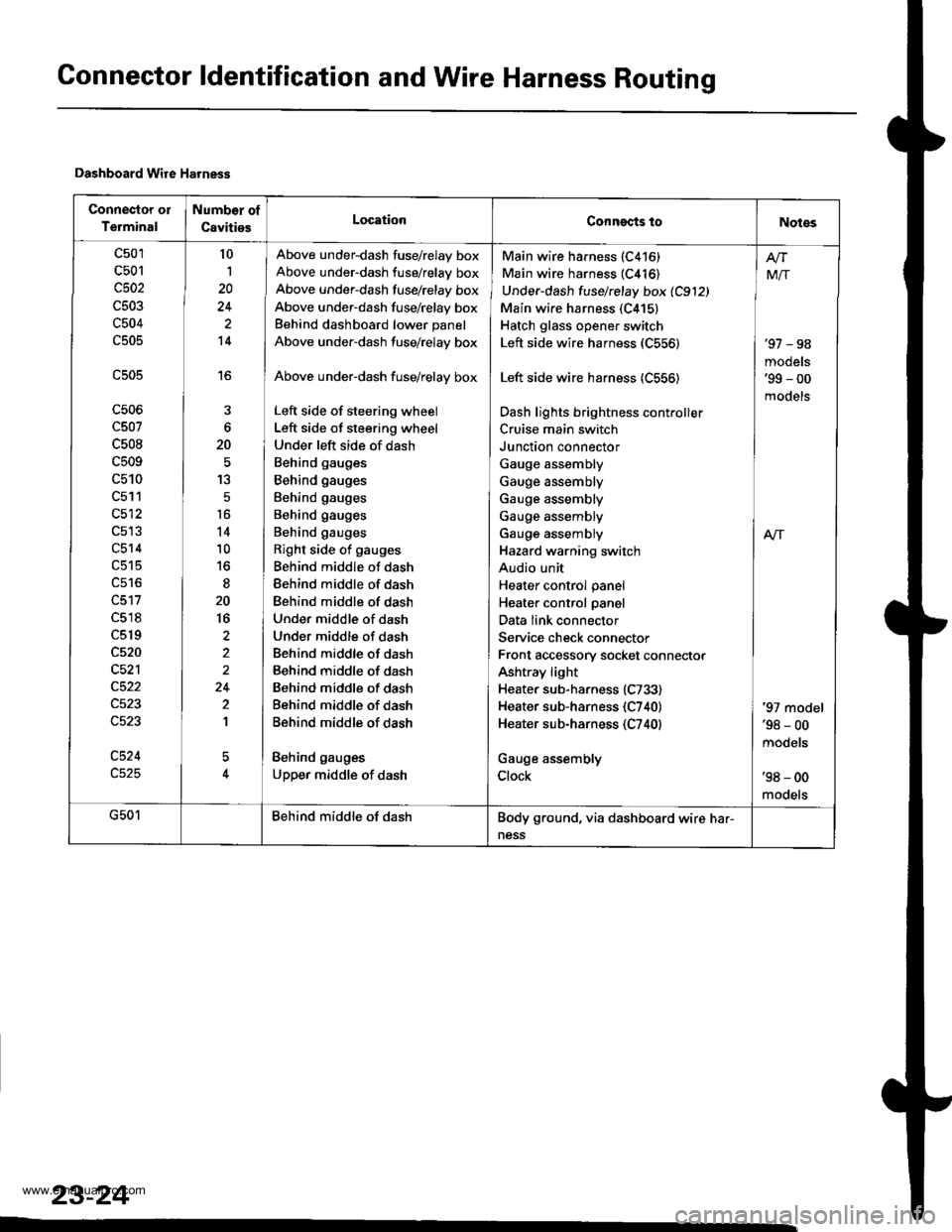
Connector ldentification and Wire Harness Routing
Dashboard Wire Harness
Connector ol
Terminal
Numb€r of
CavitiesLocationConngcts toNotes
c501
c501
c502
c503
c504
c505
c506
c507
c508
c509
c510
c511
c512
c514
c518
c519
c520
c521
c524
10
1
20
14
16
6
20
13
5
t6
14
10
to
20
16
2
24
2
1
5
Above under-dash fuse/relay box
Above under-dash fuse/relay box
Above under-dash fusehelay box
Above under-dash fuse/relay box
Behind dashboard lower panel
Above under-dash fuse/relay box
Above under-dash fuse/relay box
Left side of steering wheel
Left side of steering wheel
Under left side of dash
Behind gauges
Behind gauges
Behind gauges
Behind gauges
Behind gauges
Right side of gauges
Behind middle of dash
Behind middle of dash
Behind middle of dash
Under middle of dash
Under middle of dash
Behind middle of dash
Behind middle of dash
Behind middle of dash
Behind middle of dash
Behind middle of dash
Behind gauges
Upper middle of dash
Main wire harness (C416)
Main wire harness (C416)
Under-dash fuse/relay box 1C912)
Main wire harness (C415)
Hatch glass opener switch
Left side wire harness (C556)
Left side wire harness (C556)
Dash lights brightness cont.oller
Cruise main switch
Junction connector
Gauge assembly
Gauge assembly
Gauge assembly
Gauge assembly
Gauge assembly
Hazard warning switch
Audio unit
Heater control panel
Heater control panel
Data link connector
Service check connector
Front accessory socket connector
Ashtray light
Heater sub-harness (C733)
Heater sub-harness {C740}
Heater sub-harness (C740)
Gauge assembly
Clock
'97 - 98
models'99 - 00
models
Mir
A/r
'97 model'98 - 00
mooets
'98 - 00
models
G501Behind middle of dashBody ground, via dashboard wire har-
ness
23-24
www.emanualpro.com
Page 1203 of 1395

Power Distribution
Fuse-to-Gomponent(sl Index (numerical sequence)
Under-hood Fuse/Rolay Box:
41
43
44
46
47
48
49
50
52
Capacity
'100 A
40A
7.5 A
15 A
40A
7.5 A
30A
204
204
15 A
10A
40A
40A
204
20A
Capacity
40A
204
7.5 A
wiro ColorFuseCircuit(s) Prot€cted
A
lgnition switch (BAT)
lntegrated control unit
Ceiling lights
Spotlights
PGM-Fl main relay
Not used
No. 7, 8, 10, 11 fuse in the under-dash fuse/relay box
Audio unit
Clock {'98 - 00 models)
Data link connector ('98 - 00 models)
ECM (VBU) {'98 - 00 models: M/T)
Heater control panel
PCM (VBU) (A./T)
Combination light switch (via under-dash fuse/relay box)
No. 20, 33 fuse in the under-dash fuss/relay box
Not used
Rear window defogger (via relay)
Door lock control unit
Hatch glass opener solenoid
Keyless door lock control unit ('98 - 00 models)
Horn relay
Horns (via relay)
via brake switch:
ABS control unit
Brake lights
Cruise control unit
ECM ('98 - 00 models: M/T)
High mount brake iight
PCM (4./T)
Trailer lighting connector
Turn signal/hazard relay (via switch)
Option connector (+B)
No. 6 fuse in the under-dash fuse/relay box
Blower motor (via relay)
Condenser fan motor (via relay)
Ay'C compressor clutch (via relay)
Radiator fan motor (via relay)
Wire Color Circuitls) Protoct
53
54
50
WHT/BLK
WHT/RED
WHT/BLK
WHT/BLU
WHT/BLU
WHT
WHT/GRN
WHT/GRN
WHT/GRN
WHT/BLK
WHT/RED
BLU/WHT
WHT
RED
BLK/RED
Under-hood ABS Fuss/nehy Box:
Fusg
61WHT
WHT/GRN
BRN/YEL
ABS pump motor {via relay}
ABS control unit
ABS control unit
{cont'd)
23-43
www.emanualpro.com
Page 1204 of 1395

Power Distribution
Fuse
1
3
5
6
7
I
9
10
11
12
13
14
"^
RED/B LU
RED/GRN
WHT/BLK
RED/VVHT
YEUBLK
RED
GRN/BLK
BLU/BLK
YEVBLK
YEUGRN
RED
BLK/YE L
BLK/VVHT
17
7.5 A
7.5 A
BLVBLU
BLKA/EL
18
19
20
22
7.54
7.54
l0 A
10 A
YEUBLK
YEVRED
BLKAr'YHT
RED /VHT
RED/YE L
Fuse-to-Component(sl Index (numerical sequencel (cont'dl
Under-dash Fuse/Relay Box:
Capacity
10 A
10 A
10 A
10 A
20A
204
15A
204
204
7.5 A'15 A
7.5 A
7.5 A
Wire ColorCircuit{s) Protected
Not used
Not used
Rear window washer motor (via switch)
Rear window wiper control unit ('97 model)
Rear window wiper motor
Daytime running rights resister {Canada)
Right headlight {High beam}
Daytime running rights resister (Canada)
High beam indjcator light
Left headlight (High beam)
Rear accessory socket (via relay)
Left rear power window motor (via switch)
Right rear power window motor (via switch)
Distributor (ignition control module)
Front passenger's power window motor (via switch)
Driver's power window motor {via switch)
Power window master switch (power window control unit)
Turn signal/hazard relay (via switch)
PGM-FI main relay
SRS unit (VA)
Cruise control unit (via switch)
Cruise main switch indicator light
Alternator
Charging system light
ELD unit (USA)
EVAP bypass solenoid valve ('98 - 00 models)
EVAP control canister vent shut valve ('98 - 00 models)
EVAP purge control solenoid valve
Primary HO2S
Secondary H02S
VSS
ABS control unit
Option connector (lG2)
Ay'C compressor clutch relay
Blower motor high relay
Blower motor relay
Condenser fan relay
Heater control panel
Left power mirror actuators (via switch)
Mode control motor
Radiator fan relay
Recirculation control motor
Right power mirror actuators (via switch)
Daytime running lights control unit (Canada)
Back-up lights
Reverse relay (A"/T)
Daytime running lights control unit (Canada)
Right headlight (Low beam)
Left headlight (Low beam)
23-44
www.emanualpro.com
Page 1205 of 1395

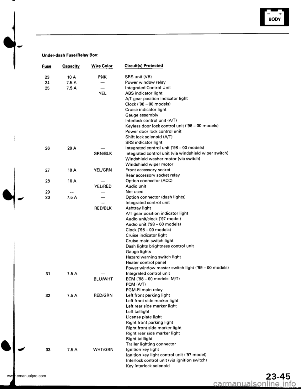
under-dash Fuse/Relay Box:
Fuse Capacitywir6 ColorCircuit(sl Protocted
SRS unit (VB)
Power window relay
Integrated Control Unit
ABS indicator light
A/T gear position indicator light
Clock ('98 - 00 models)
Cruise indicator light
Gauge assembly
Interlock control unit (A,/T)
Keyless door lock control unit ('98 - 00 models)
Power door lock control unit
Shift lock solenoid (lVT)
SRS indicator light
Integrated control unit ('98 - 00 models)
Integrated control unit (via windshield wiper switch)
Windshield washer motor (via switch)
Windshield wiper motor
Front accessory socket
Rear accessory socket relay
Option connector (ACC)
Audio unit
Not used
Option connector (dash lights)
Integrated control unit
Ashtray light
A,/T gear position indicator light
Audio univclock ('97 model)
Audio unit ('98 - 00 models)
Clock ('98 - 00 models)
Cruise indicator light
Cruise main switch light
Dash lights brightness control unit
Gauge lights
Hazard warning switch light
Heater control panel
Power window master switch light ('99 - 00 models)
Integrated control unit
ECM ('98 - 00 models: M/T)
PCM (4./T)
PGM-Fl main relay
Left front pa.king light
Left front side marker light
Left rear side marker light
Left taillight
License plate light
Right front parking light
Right front side marker light
Right rear side marker light
Right taillight
Trailer lighting connector
lgnition key light
lgnition key light control unit ('97 model)
Interlock control unit (via ignition switch)
Key interlock solenoid
25
PNK
;
10 A
7.5 A
7.5 A
28
10A
10A
7.5 A
204
7.5 A
7.5 A
GRN/BLK
YEUGRN
YEURED
a, olrL"
29
30
BLU,ryVHT
RED/GRN
7.5 AWHT/G R N
23-45
www.emanualpro.com
Page 1207 of 1395

BLKG401
GroundWir€ ColorComponent or Circuits Grounded
ABS indicator circuit
ABS control unit
Ashtray light
A/T gear position indicator dimming circuit
Brake fluid level switch
Clock ('98 - 00 models)
Clutch inrerlock switch (M/T)
Clutch switch (Mff)
Cruise main switch
Cruise indicator circuit
Cruise control unit
Dash lights brightness controller
Data iink connector
Daytime running rights control unit (Canada)
Front accessary socket
Gauge and indicators
Heater control panel
lgnition key light control unit ('97 model)
lgnition key switch
Integrated control unit
Interlock control unit (Ay'T)
Parking pin switch {A,/T)
Power window relay
Rear accessary socket relay
Bear window defogger relay
Rear window wiper control unit ('97 model)
Service check connector
Spotlights
SRS indicator circuit
Turn signal/hazard relay
Windshield wiper motor
Windshield wiper/washer switch- plus everything grounded through G402
ABS control unit
Blower motor relay
Blower motor high relay
ELD unit (USA)
Power transistor- plus everything grounded through G401
BLKG402
{cont'd)
23-47
www.emanualpro.com
Page 1245 of 1395

Turn SignallHazard Flasher System
UNDEF HOOD FUSE/NELAY BOX
N0.30 (7.54)FUSE
V
IREO/BLK
l,
t'IFqD
.+
DASH LIGHTSBSIGHTNESSCONTROLLER
HAZARDWARNINGswtTcH
_ GRN/ORN
YEUBLK
WHTiELK
GRNAVHT
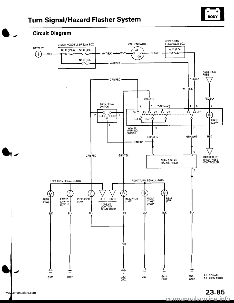
O -. Circuit Diagram
BATTEFY
@**'
q-
103
GRN/ORN
INDICATOR
TFAILERLIGHTINGCONNECTOR
INDICATOR(1.4W)
BLK
G553
IGN T]ON SWITCHUNDER.OASHFUSE/RELAY BOX
No 12 (7.sA)
l----r-l-----i-F-- --------_ \
BtK
G401G402
:i1r'97model*2 :'98-00 models
23-85
www.emanualpro.com
Page 1246 of 1395

Turn SignallHazard Flasher System
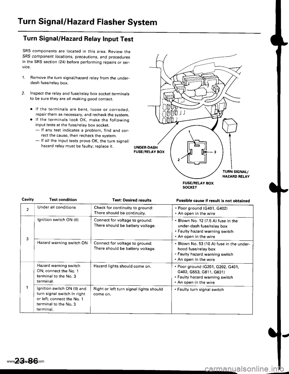
Turn Signal/Hazard Relay Input Test
SRS components are located in this area. Review theSRS component /ocations, precautions, ano proceoures
in the SRS section (24) before performing repairs or ser-vice.
1.Remove the turn signal/hazard relay from the under-dash fuse/relay box.
Inspect the relay and luselrelay box socket terminals
to be sure they are all making good contact.
lf the terminals are bent, loose or corroded,reparr them as necessary, and recheck the system.lf the terminals look OK, make the following
input tests at the fuse/relay box socket.- lf any test indicates a problem, find and cor-
rect the cause, then recheck the system.- lf all the input tests prove OK, the turn signal/
hazard relay must be faulty; replace it.
CavityTest conditionTesl: Desired results
FUSE/RCLAY BOXSOCKET
Possible cause if result is not obtained
'1
IF\_-'l -]l
$ o{+-/ll ll
2Under all conditionsCheck for continuity to ground:
There should be continuity.
. Poor ground (G401, G402). An open in the wjre
3
lgnition switch ON (lllConnect for voltage to ground:
There should be battery voltage.
Blown No. 12 (7.5 A) fuse in the
under-dash fuse/relay box
Faulty hazard warning switch
An open in the wire
Hazard warning switch ONConnect for voltage to ground:
There should be battery voltage.
Blown No. 53 (10 A) fuse in the under-
hood fuse/relay box
Faulty hazard warning switch
An open in the wire
1
Hazard warning switch
ON; connect the No. 1
terminal to the No. 3
terminal.
Hazard lights should come on.Poor ground (G201. c202, c401,
G402, G553, G611, c631)
Faulty hazard warning switch
An open in the wire
lgnition switch ON (ll) and
turn signal switch in right
or left; connect the No. 'l
terminal to the No.3
terminal.
Right or left turn signal lights should
come on.
. Faulty turn signal switch
23-86
www.emanualpro.com
Page 1247 of 1395
![HONDA CR-V 1998 RD1-RD3 / 1.G Workshop Manual
Turn Signal Switch Test
1.
4.
Remove the drivers dashboard lower cover and the
knee bolster (see section 20).
Remove the steering column covers {see section
17]-.
Disconnect the 4P and 7P connectors HONDA CR-V 1998 RD1-RD3 / 1.G Workshop Manual
Turn Signal Switch Test
1.
4.
Remove the drivers dashboard lower cover and the
knee bolster (see section 20).
Remove the steering column covers {see section
17]-.
Disconnect the 4P and 7P connectors](/img/13/5778/w960_5778-1246.png)
Turn Signal Switch Test
1.
4.
Remove the driver's dashboard lower cover and the
knee bolster (see section 20).
Remove the steering column covers {see section
17]-.
Disconnect the 4P and 7P connectors from the
switch.
Remove the screws, and slide the switch toward the
driver's door.
Check for continuity between the terminals in each
switch position according to the table.
Position
Terminal12
RIGHTo-
Neutral
LEFTo---o
q
tl-
swtTcH
Hazard Warning Switch Test
1. Remove the center panel {see section 20).
2. Remove the two screws, then remove the switch
from the center air vent.
HAZARD
Check for continuitv between the terminals in each
switch position according to the table.
Terminal
t**--\
2357810
OFF(9U(_)
ONo@oooo
lNol us€d)
23-87
www.emanualpro.com