ignitionswitch HONDA CR-V 1998 RD1-RD3 / 1.G Workshop Manual
[x] Cancel search | Manufacturer: HONDA, Model Year: 1998, Model line: CR-V, Model: HONDA CR-V 1998 RD1-RD3 / 1.GPages: 1395, PDF Size: 35.62 MB
Page 392 of 1395
Fuel Supply System
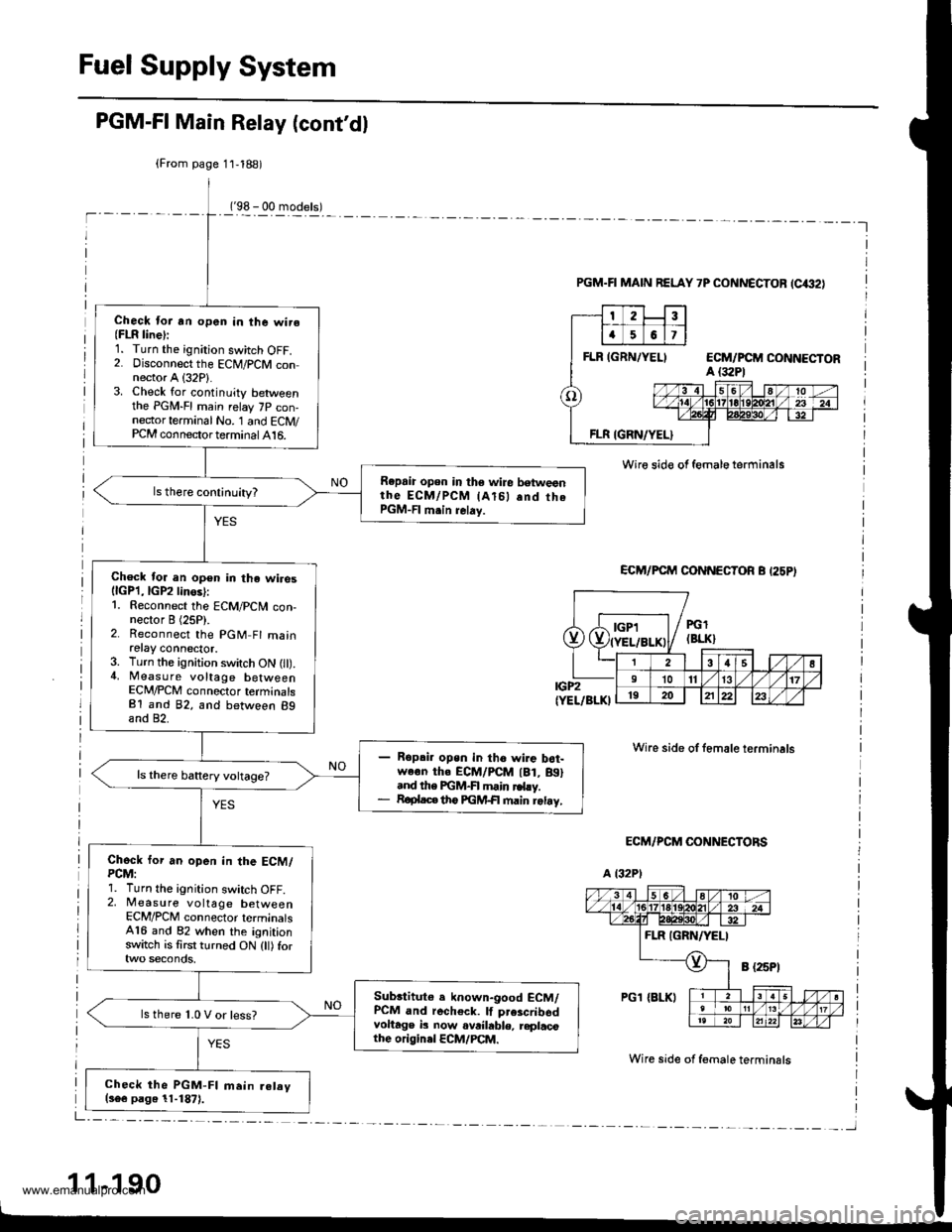
PGM-FI Main Relay (cont'dl
('98 - 00 models)-l
(From page 11,188)
Check lor an open in the wire(FLR line):1. Turn the ignition switch OFF.2. Disconnect the ECM/PCM connector A (32P1.3. Check for continuity betweenthe PGM-FI main relay 7P con-nector terminal No. '1 and ECM/PCM connector terminal 416.
Repaia open in the wire betweenthe EcM/PcM lAl5l .nd thePGM-FI m.in relay.
Check for an open in the wiresllcPl,lGP2linos):1. Reconnect the ECM/PCN4 con-nector I (25P).2. Reconnect the PGM Fl mainretay connector.3. Turn the ignition switch ON l).4, Measure voltage betweenECM/PCM connector terminalsB1 and 82, and between 89and 82.
Ropai. open in tho wire b6t-we€n th. ECM/PCM lBt, Btl.nd the FGM-FI main rd.y.R€plac€ th6 FGM+| main retay,
Chock for an open in the ECM/PCM:1. Turn the ignition switch OFF.2, Measure voltage betweenECM/PCM connector terminals416 and 82 when the ignitionswitch is first turned ON (tl) for
Subrtitute e known-good ECM/PCM and recheck. lf prescribsdvoltage b now ovrihble, replacothe originel ECM/PCM.
ls there 1.0 V or less?
Check the PGM-FI main.elav(s6e page 11-1871.
PGM.FI MAIN RELAY 7P CONNECTOF (C€2)
Wire sid€ of female terminals
ECM/PCM CONNECTOR B I25PI
IGP2(YEL/BLKI
ECM/PCM CONNECTORS
a t32Pl
Wire side of female terminals
Wire side of f€male terminsls
1 1-190
Dde"Jt;;liL-F-T--
PGl(BLK}
38s l1011131719202122
www.emanualpro.com
Page 537 of 1395
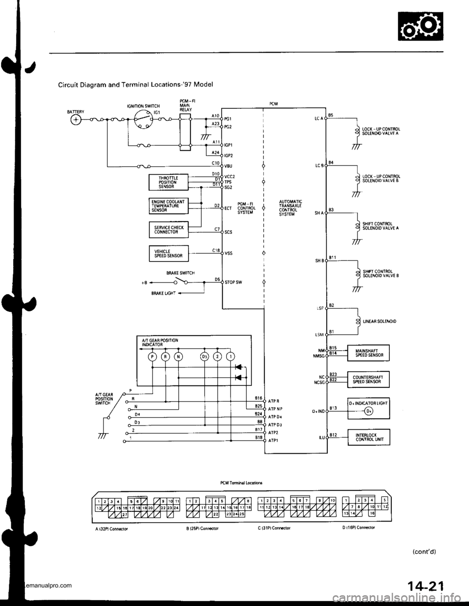
Circuit Diagram and Terminal Locationsr9T Model
IGNITIONSWITCH
LOC( UPCONTROL
LOCK UPCONTROLSOLEITOIDVALVE B
sf Frc0|lltF0LSOLENOIDVALVE A
sHrFr c0r{TnoLSOLEI{OID VALVE B
UNEASSOLINOID
14-21
www.emanualpro.com
Page 648 of 1395
Electrical Troubleshooting ('gg - 00 Modelsl
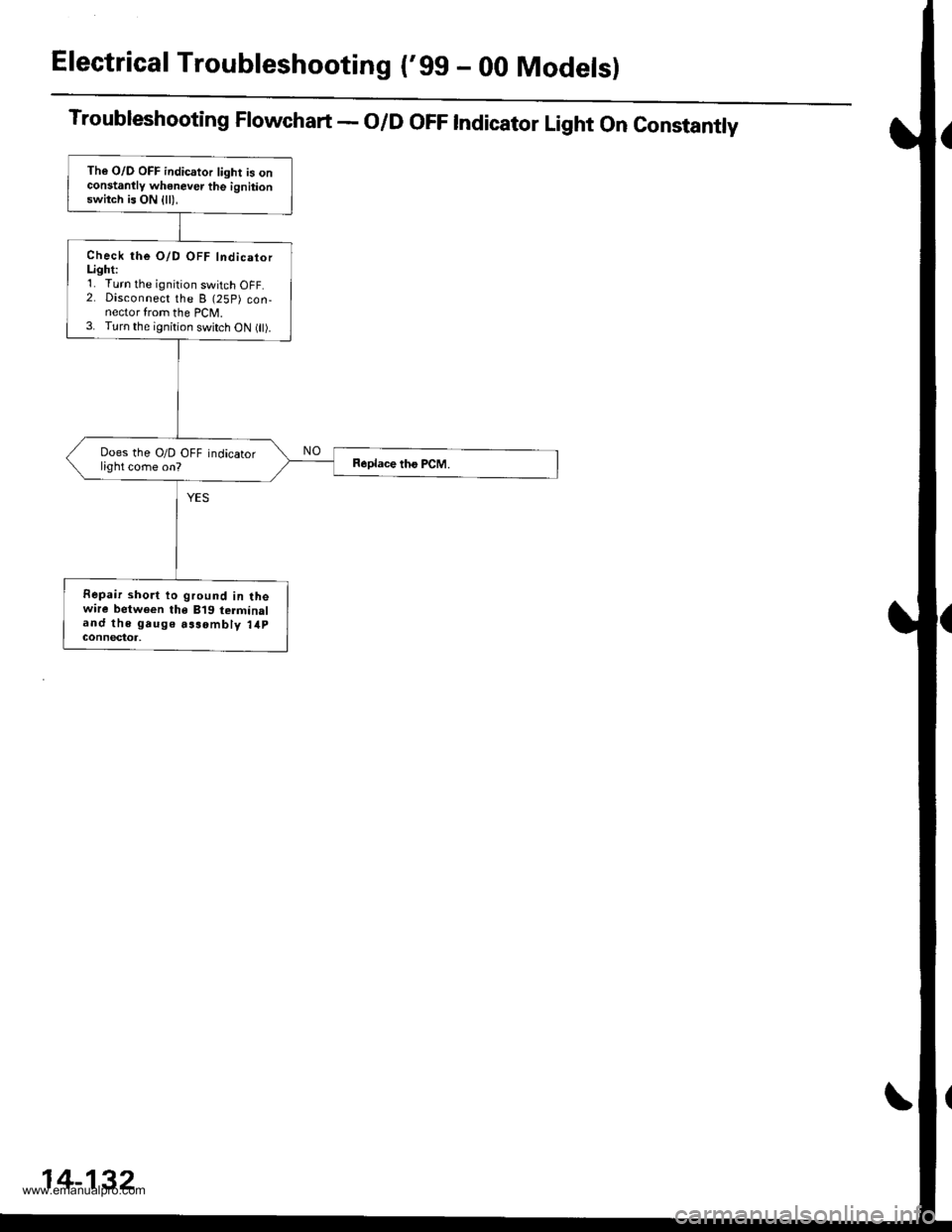
Troubleshooting Flowchart - O/D OFF Indicator Light On Constantly
The O/D OFF indicator light is onconstanllv whenever the ignitionswitch is ON {ll),
Check the O/D OFF IndicatorLighti'1. Turn the ignition switch OFF.2. Disconnect the B (25P) con-nector from the PCM.3. Turn the ignition switch oN flt).
Does the O/D OFF indicatorlight come on?
Fepair short to ground in lhewire between the B'19 terminaland the gauge aasombly 14pGOnnectot,
14-132
www.emanualpro.com
Page 1126 of 1395
Troubleshooting
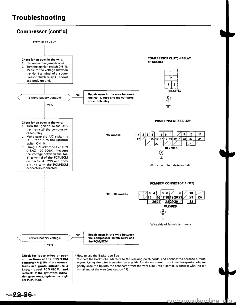
Compressor (cont'dl
COMPRESSOR CLUTCH RELAY4P SOCKET
1
2
43
BLK/YEL
PCM CONNECTOB A I32P)
'97 model:
Wire side of female terminals
PCM/ECM CONNECTOR A {32P}
38 - 00 models:
Wire side of {em6le terminals
* How to use the BackDrobe SetsConnect the backprobe adapters to the stacking patch cords, and connect the cords to a multi-meter. Using the wire insulation as a guide for the contoured tip ot the backprobe adapter,gently slide the tip into the connector trom the wire side until it comes in contact with the teFminalend o{the wire {see section l1).
Frcm page 22-34
Ch6ck for an open in the wire:1. Disconnect the jumper wire.2. Turn the ignition switch ON (ll).
3, Measure the voltage betweenthe No. 4 terminal ot the com'pressor clutch relay 4P socketand body ground.
Repair op.n in the wire betweenthe No. l7 fu3e and the compres-sor clutch ielay.
Check for an opon in the wire:1. Turn the ignition switch OFF,then reinstall the compressorclutch relay.2. Make sure the A"/C switch isOFF, then turn the ignitionswitch ON (ll).
3. Using a *Backprobe Set (T/N
07SAZ - 001000A), measurethe voltage between the No.17 terminal ol the PCM/ECMconnector A (32P) and bodyground with the PC M/ECMconnectors connected,
Repair open in lhe wire betwoonthe compressor clutch r6lay andthe PCM/ECM.
Check tor loose wires or Doorconnections at the PCM,/ECMconnecto. A {32P1. lf the connec-tions are good, sub3titute aknown-good PCM/ECM, androcheck. lf the symptom/indica-tion goas away, replac€ the origi-nal PCM/ECM.
126I1011
12151617'181S222321
BLK/RED
22-36
www.emanualpro.com
Page 1272 of 1395
Rear Window Defogger
Function Test
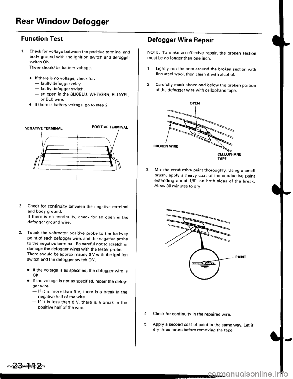
1. Check for voltage between the positive terminal andbody ground with the ignition switch and defoggerswitch ON.
There should be battery voltage.
. lf there is no voltage. check for:- faulty defogger relay.- faulty defogger switch.- an open ,n the BLK/BLU, WHT/GRN, BLU/YEL,
or BLK wire.
. lf there is battery voltage, go to step 2.
POSITIVE TERMINAL
Check for continuity between the negative terminaland body ground.
lf there is no continuity, check for an open in thedefogger ground wire.
Touch the voltmeter positive probe to the halfwaypoint of each defogger wire, and the negative probe
to the negative terminal. Be careful not to scratch ordamage the defogger wires with the tester probe.There should be approximately 6 V with the ignitionswitch and the defogger switch ON.
. lf the voltage is as specified, the defogger wire isoK.
. lf the voltage is not as specified, repair the defog-ger wire.- lf it is more than 6 V, there is a break in thenegative half of the wire.- lf it is less than 6 V, there is a break in thepositive half of the wire.
23-112
Defogger Wire Repair
NOTE: To make an effective repair, the broken sectionmust be no longer than one inch.
1. Lightly rub the area around the broken section withfine steel wool, then clean it with alcohol.
2. Carefully mask above and below the broken portionof the defogger wire with cellophane tape.
CELLOPHANETAPE
Mix the conductive paint thoroughly. Using a smallbrush, apply a heavy coat of the conductive paint
extending about 1/8" on both sides of the break.Allow 30 minutes to dry.
Check for continuity in the repaired wire.
Apply a second coat of paint in the same way. Let itdry three hours before removing the tape.
5,
OPEN
www.emanualpro.com
Page 1333 of 1395
Troubleshooting
From page 24-35
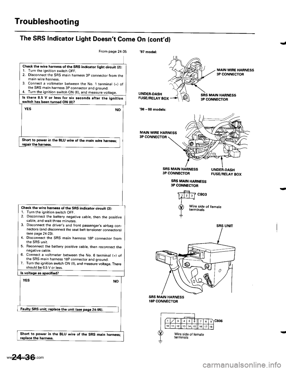
Check lhe wire harness otthe SRS indicator light circuit l2l:L Turn the ignitjon switch OFF.2. Disconnect the SRS main harness 3p connector from themain wire harness.3. Connect a voltmeter between the No. I terminal (+) ofthe SRS main harness 3P connector and qround.4. Turn the ignition switch ON (ll), and measure voltaqe.
ls there 8.5 V o. less tor six seconds atter the ignitionswitch has been turned ON
Short to power in th€ BLU wire of the main wiro halno3s;
Check th€ wire hahess of th6 SRS indicator ci.cuit {31:1. Turn the ignition switch OFF.2. Disconnect the battery negative cable, then the positivecable, and wait three minutes.3. Disconnect the driver's and front passenger,s airbag con-nectors {and disconnect the seat belt tensioner connectors}(see page 24-23).4. Disconnect the SRS main harness 18p connector from
5. Reconnect the battery positive cable, then reconnect thenegative cable.6. Connect a voltmeter between the No. 6 terminal (+) ofthe SRS main harness 'l8P connector and ground.7. Turn the ignition switch ON (ll), and measure voltage. Thereshould be 0.5 V or less.
Short to power in the BLU wire oI the SRS main harngas;
The SRS Indicator Light Doesn't Come On (cont,dl
'97 modol:
J
MAIN WIRE HARNESS3P CONNECTOR
UNDER.DASHFUSE/RELAY BOX
'98 - 00 models:
SRS MAIN HARN€SS3P CONNECTOR
MAIN WIRE HARNESS3P CONNECTOR
SRS MAIN HARNESS3P CONNECTOR
SRS MAIN HARNESS3P COI{NECTOB
FUSE/RELAY BOX
c803
SRS MAIN HARNESS18P CONNECTOR
24-36
www.emanualpro.com