And HONDA CR-V 1999 RD1-RD3 / 1.G Workshop Manual
[x] Cancel search | Manufacturer: HONDA, Model Year: 1999, Model line: CR-V, Model: HONDA CR-V 1999 RD1-RD3 / 1.GPages: 1395, PDF Size: 35.62 MB
Page 1280 of 1395
Wipers/Washers
1.
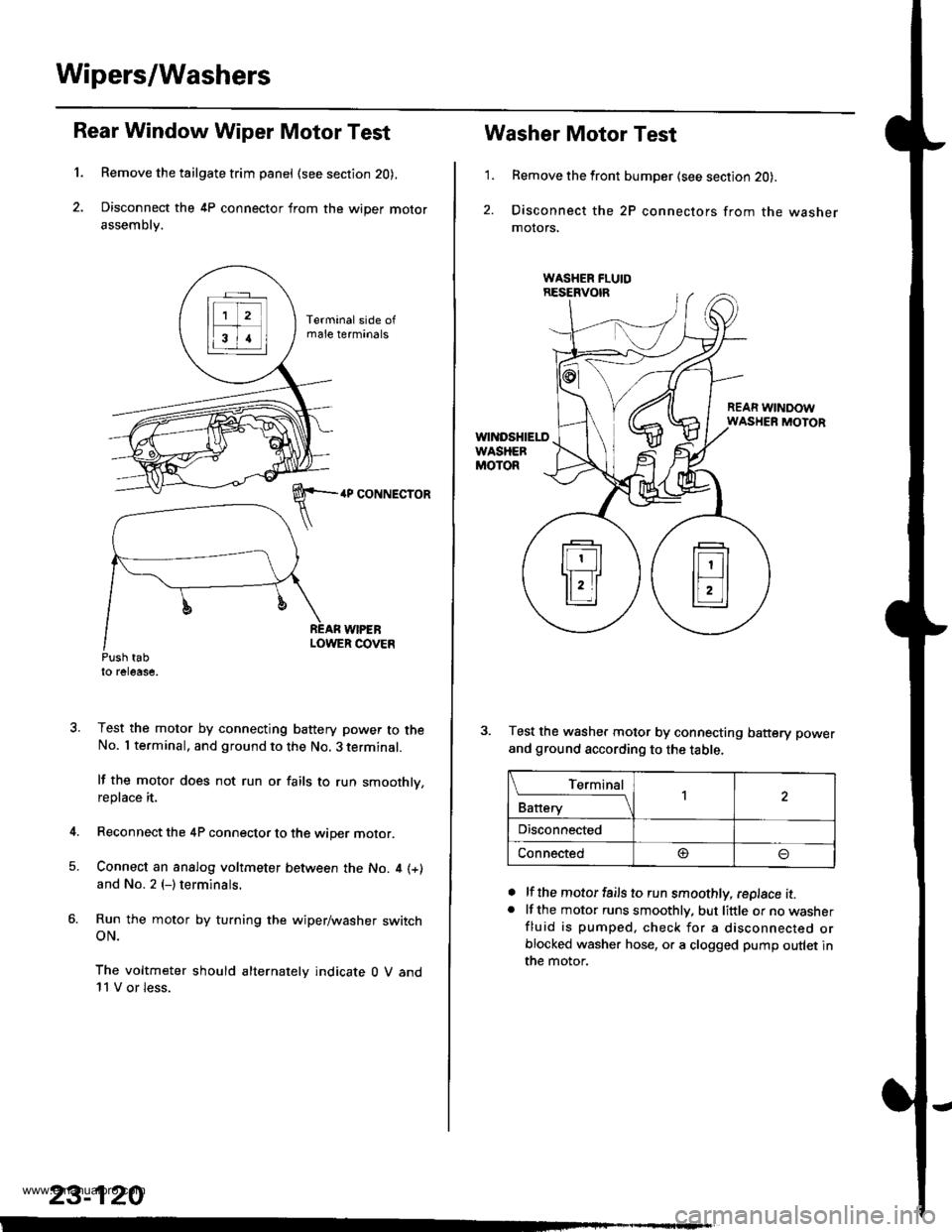
Rear Window Wiper Motor Test
Remove the tailgate trim panel (see section 20),
Disconnect the 4P connector from the wiper motor
assembly.
4P CONNECTOR
WIPEBLOWER COVEnPush tabto release,
Test the motor by connecting battery power to theNo. I terminal, and ground to the No. 3 terminal.
lf the motor does not run or fails to run smoothly,replace it.
Reconnect the 4P connector to the wiper motor.
Connect an analog voltmeter between the No. 4 (+)
and No. 2 (-) terminals.
Run the motor by turning the wiper/washer switchoN.
The voltmeter should alternately indicate 0 V and11 V or less.
4.
5.
23-120
1.
Washer Motor Test
Remove the front bumper (see section 20).
Disconnect the 2P connectors from the washermolors,
REAR WINDOWWASHER MOTOR
Test the washer motor by connecting battery power
and ground according to the table.
lf the motor fails to run smoothly, replace it.lf the motor runs smoothly, but little or no washerfluid is pumped, check for a disconnected orblocked washer hose, or a clogged pump outlet inthe motor.
a
a
L_Iq'.r91
Battery
,l
Disconnected
Connected@
www.emanualpro.com
Page 1281 of 1395
Hatch Glass Opener
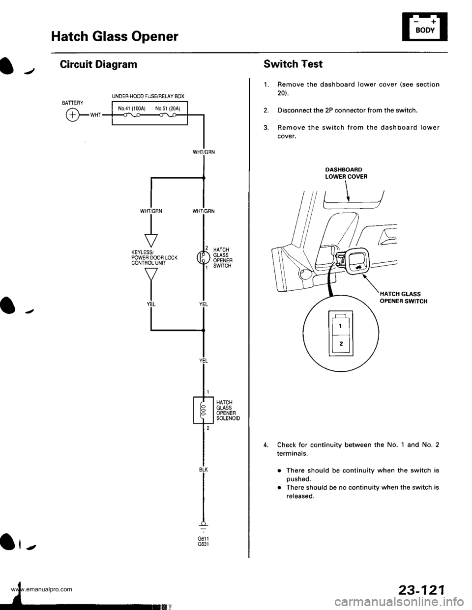
Circuit Diagram
BATTEFY
@*"
UNDER.H@D FUSE/RELAY BOX
|-*;rr^!...',r,*;l.......1<\o<
+l
I
I
IWHT/GRN
WHT/GRN
II
rt
KEYLESSiPOWEF DOOB LOCKCONTROL UNIT
V
IIIYEL
HATCHGLASSOPENERsoLENOr0
J
TBLK
I
out,G631
WHT/GBN
Ot-
23-121
1. Remove the dashboard lower cover (see section
20).
2. Disconnect the 2P connector from the switch.
3. Remove the switch from the dashboard lower
cover.
Switch Test
DASHBOANDLOWER COVER
HATCH GLASSOPENER SWITCH
Check for continuity between the No. 1 and No. 2
terminals.
. There should be continuity when the switch is
pushed.
. There should be no continuity when the switch is
released.
www.emanualpro.com
Page 1282 of 1395
Hatch Glass Opener
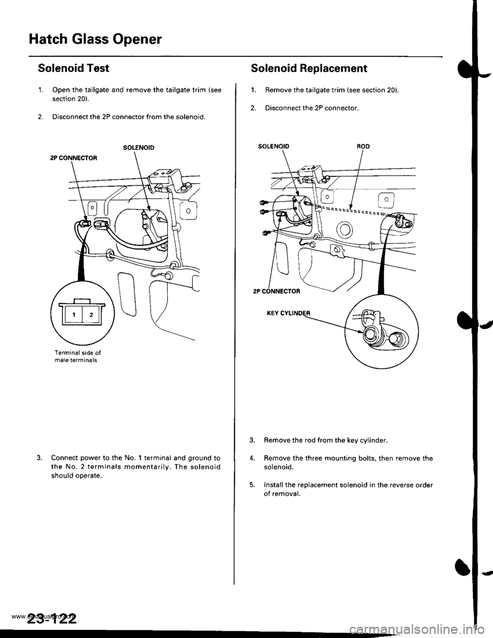
Solenoid Test
1. Open the tailgate and remove the tailgate trim (see
section 20).
2. Disconnect the 2P connector from the solenoid.
Terminalsade ofmale termtnals
Connect power to the No. 1 terminal and ground to
the No.2 terminals momentarilv. The solenoid
should ooerate.
SOLENOID
23-122
't.
2.
4.
Solenoid Replacement
Remove the tailgate trim (see section 20).
Disconnect the 2P connector.
Remove the rod from the key cylinder.
Remove the three mounting bolts, then remove the
solenoid.
Install the replacement solenoid in the reverse oader
of removal.
www.emanualpro.com
Page 1286 of 1395
Power Door Locks
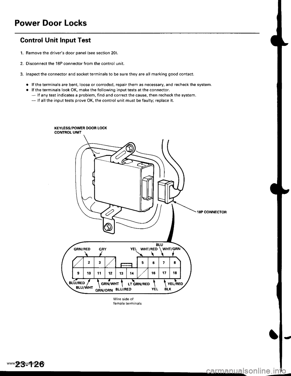
Gontrol Unit Input Test
1. Remove the driver's door panel (see section 20).
2. Disconnect the 18P connector from the control unit.
3. lnspect the connector and socket terminals to be sure they are all marking good contact.
. lf the terminals are bent, loose orcorroded, repairthem as necessary, and recheck the system.
. lf the terminals look OK, make the following input tests at the connector.- lf any test indicates a problem, find and correct the cause, then recheck the system.- lf all the input tests prove OK, the control unit must be faulty; replace it.
BLUGRN/BED GRY YEL WHT/REO WHT/GRN
723,/58
101t12 1131416171E
GRN/WHT I LT
18P CONNECTON
female terminals
23-126
www.emanualpro.com
Page 1287 of 1395
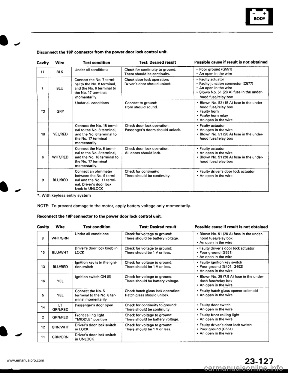
Disconnoci the 18P connestor from the pow€r door lock control unit.
Cavity WireTest conditionTost: Dcsired resultPo$ible csuse il result is not obtainod
Possible cause if result is not obtain€d
*: With keyless entry system
NOTE: To prevent damage to the motor, apply battery voltage only momentarily.
Feconnoct the 18P conneqtor to the power door lock control unit,
Cavity Wir6Test conditionTost: D€sirod result
118LKUnder all conditionsCheck for continuity to ground:
Ther€ should be continuity.
. Poorground (G55'l). An open in the wire
7BLU
Connect the No. 7 termi'nalto the No. 8 terminal,and the No. 6 terminal tothe No. 17 terminalmomentarily.
Check door lock operation:Driver's door should unlock.Faulty actuatorFaulty junction connector (C577)
An open in the wireBlown No. 51 (20 Al{use in the under-
hood fuse/relay box
GRY
Under all conditionsConnect to ground:Horn should sound,Blown No. 52 (15 A)tuso in the under-hood fuse/relay boxFaulty hornFaulty horn relayAn open in tho wire
YEURED
Connect the No. 'l8 termi-nalto the No. 8 terminal,and the No. 6 terminal tothe No. 17 terminalmomentarily.
Check door lock operation:Passenger's doors should unlock.Faulty actuatorAn open in the wireBlown No.51 (20 A)fuse in the under-hood fuse/relay box
WHT/RED
Connect the No.6termi-nal to th6 No. I terminal,and the No. 18 terminal tothe No. 17 terminalmomentarily.
Check door lock operationlAll doors should lock.Faulty actuatorAn open in the wireBlown No. 51 {20 A) fuse in ihe under-hood fuse/relay box
9BLU/RED
Connect an ohmmeterbetween the No. 9 termi-nal and the No. l7 termi-nal. Driver's door lockknob in UNLOCK
Check for conlinuity:There should be continuity.
' Faulty driver's door lock actualor. An open in the wire
WHT/GRNUnder all conditionsCheck for voltage to ground:
There should be battery voltage.Blown No. 51 (20 Alfuse in the under-hood tuse/relay boxAn open in the wire
10BLUAVHTDriver's door lock knob inLOCKCheck tor voltage to ground:There should be 1 V or less.Faulty driver's door lock actuatorPoor ground (G551)
An open in the wire
13BLU/REDlgnition key is in the igni-tion switchCheck tor voltage to ground:
There should b€ 1 V or less.Faulty ignition key switchPoor ground (G401, G402)An open in the wire
YELlgnition switch ON (ll)Check for voltage to ground:
There should be battery voltage.Blown No. 25 (7.5 A) fuse in the under-dash fuse/relay boxAn open in the wire
5YELConnect the No. 5terminal to the No. I ter-minal momentarily
Check hatch glass lock operation:Hatch glass should unlock.
. Faulty hatch glass opener solenoid. An opon in the wire
14LTGRN,NEDPassengor's door openCheck for continuity to ground:There should b€ continuity.
. Fa(llty door switch. An open in the wire
2GRN/R€DFront ceiling light"MlDDLE" positionCheck tor voltage to ground:There should be battery voltage.Faulty lront ceiling lightAn open in the wire
12GRNAr'VHTDriver's door lock switchin LOCKCheck lor voltage to ground:There should be 1V or less.Faulty driver's door lock switchPoor ground {G551)An open in the wire' GRN/ORNDriver's door lock switchin UNLOCK-
23-127
www.emanualpro.com
Page 1288 of 1395
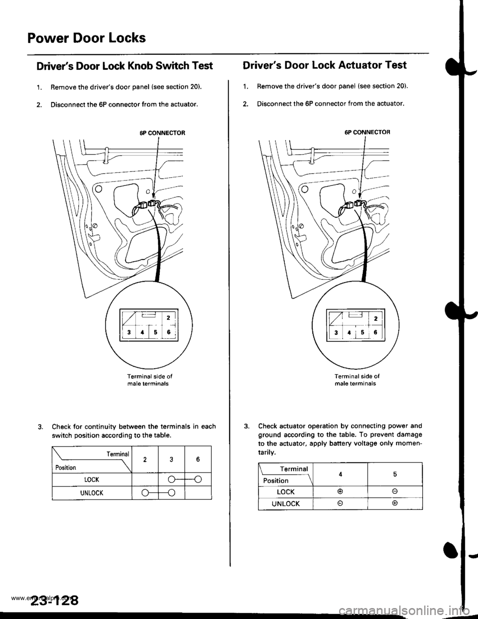
Power Door Locks
Driver's Door Lock Knob Switch Test
1. Remove the driver's door panel (see section 20).
2. Disconnect the 6P connector from the actuator.
Terminalside otmale terfiinals
Check for continuity between the terminals in each
switch position according to the table.
rsrmrnal
Position \
?6
LOCKo--o
UNLOCKo---o
23-128
.
6P CONNECTOR
Driver's Door Lock Actuator Test
1, Remove the driver's door panel (see section 20).
2. Disconnect the 6P connector from the actuator.
Terminal side ofmale terminals
Check actuator operation by connecting power and
ground according to the table. To prevent damsge
to the actuator. apply battery voltage only momen-
tarilv,
6P CONNECTOR
Terminal
F*'',1."
__l
LOCK@o
UNLOCK@
'-
www.emanualpro.com
Page 1289 of 1395
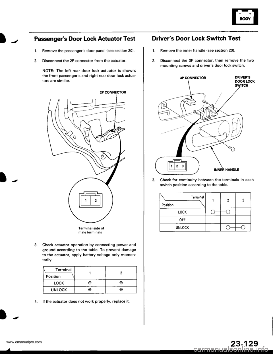
Passenger's Door Lock Actuator Test
Remove the passenger's door panel (see section 20).
Disconnect the 2P connector from the actuator.
NOTE: The left rear door lock actuator is shown;
the front passenger's and right rear door lock actua-
tors are similar.
Terminal side ofmale terminals
Check actuator operation by connecting power and
ground according to the table. To prevent damage
to the actuator, apply battery voltage only momen-
raflry.
Terminal
;;il;--r
,l
LOCK@
UNLOCK@
1.
2P CONNECTOR
4. lf the actuator does not work properly, replace it.
23-129
L
Driver's Door Lock Switch Test
Remove the inner handle {see section 20).
Disconnect the 3P connector. then remove the two
mounting screws and driver's door lock switch.
Check for continuitv between the terminals in each
switch position according to the table.
lermlnal
Position \
123
LOCKo---o
OFF
UNLOCKo--_o
www.emanualpro.com
Page 1290 of 1395
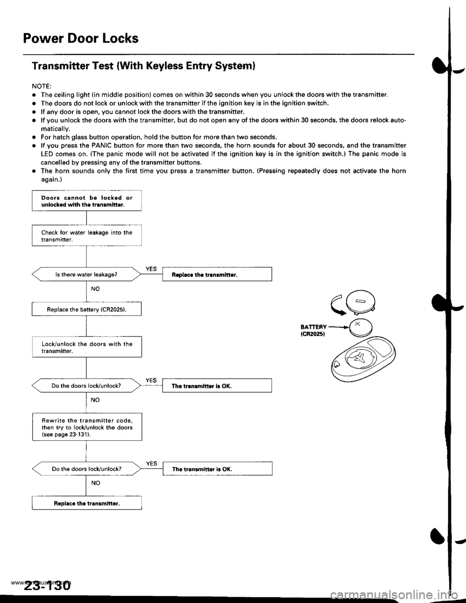
Power Door Locks
Transmitter Test (With Keyless Entry Systeml
NOTE:
. The ceiling light (in middle position) comes on within 30 seconds when you unlock the doors with the transmitter.
. The doors do not lock or unlock with the transmitter if the ignition key is in the ignition switch.
. lf any door is open, you cannot lockthe doorswith thetransmitter.
o lf you unlock the doors with the transmitter, but do not open any of the doors within 30 seconds, the doors relock auto-
matically.
. For hatch glass button operation, hold the button for more than two seconds.
. lf you press the PANIC button for more than two seconds, the horn sounds for about 30 seconds, and the transmitter
LED comes on. (The panic mode will not be activated if the ignition key is in the ignition switch.) The panic mode is
cancelled by pressing any of the transmitter buftons.
. The horn sounds only the first time you press a transmitter button, (Pressing repeatedly does not activate the horn
again.)
BATTERY{cR20251
23-130
Doors cannot bo locked orunlocked whh lhe transmitter.
Rewrite the transmitter code,then try to locldunlock the doors{see page 23-131}.
www.emanualpro.com
Page 1291 of 1395
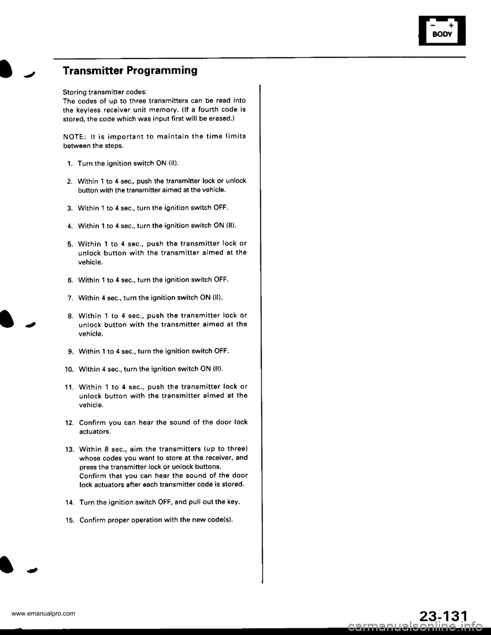
Transmitter Programming
Storing transmitter codes:
The codes of up to three transmitters can be read into
the kevless receiver unit memory (lf a fourth code is
stored. the code which was inDUt first will be erased.)
NOTE: lt is important to maintain the time limits
between the steps.
1.
11.
Turn the ignition switch ON (ll).
Within 1 to 4 sec., push the transmitter lock or unlock
button with the transmitter aimed at the vehicle.
Within 1 to 4 sec., turn the ignition switch OFF.
Within 1 to 4 sec., turn the ignition switch ON (ll).
Within 1 to 4 sec.. push the transmitter lock or
unlock button with the transmitter aimed at the
vehicle.
Within 1 to 4 sec., turn the ignition switch OFF.
Within 4 sec., turn the ignition switch ON {ll).
Within 1 to 4 sec., push the transmitter lock or
unlock button with the transmitter aimed at the
vehicle.
Within 1 to 4 sec., turn the ignition switch OFF,
Within 4 sec., turn the ignition switch ON (ll).
Within 1 to 4 sec., push the transmitter lock of
unlock button with the transmitter aimed at the
vehicle.
Confirm you can hear the sound of the door lock
aduators.
Within 8 sec., aim the transmitters (up to three)
whose codes you want to store at the receiver, and
press the transmitter lock or unlock buttons.
Confirm that you can hear the sound of the door
lock actuators after each transmitter code is stored.
Turn the ignition switch OFF, and pull out the key.
Confirm proper operation with the new code{sl.
-
o.
1.
9.
10.
12.
13.
14.
-
15.
23-131
www.emanualpro.com
Page 1294 of 1395
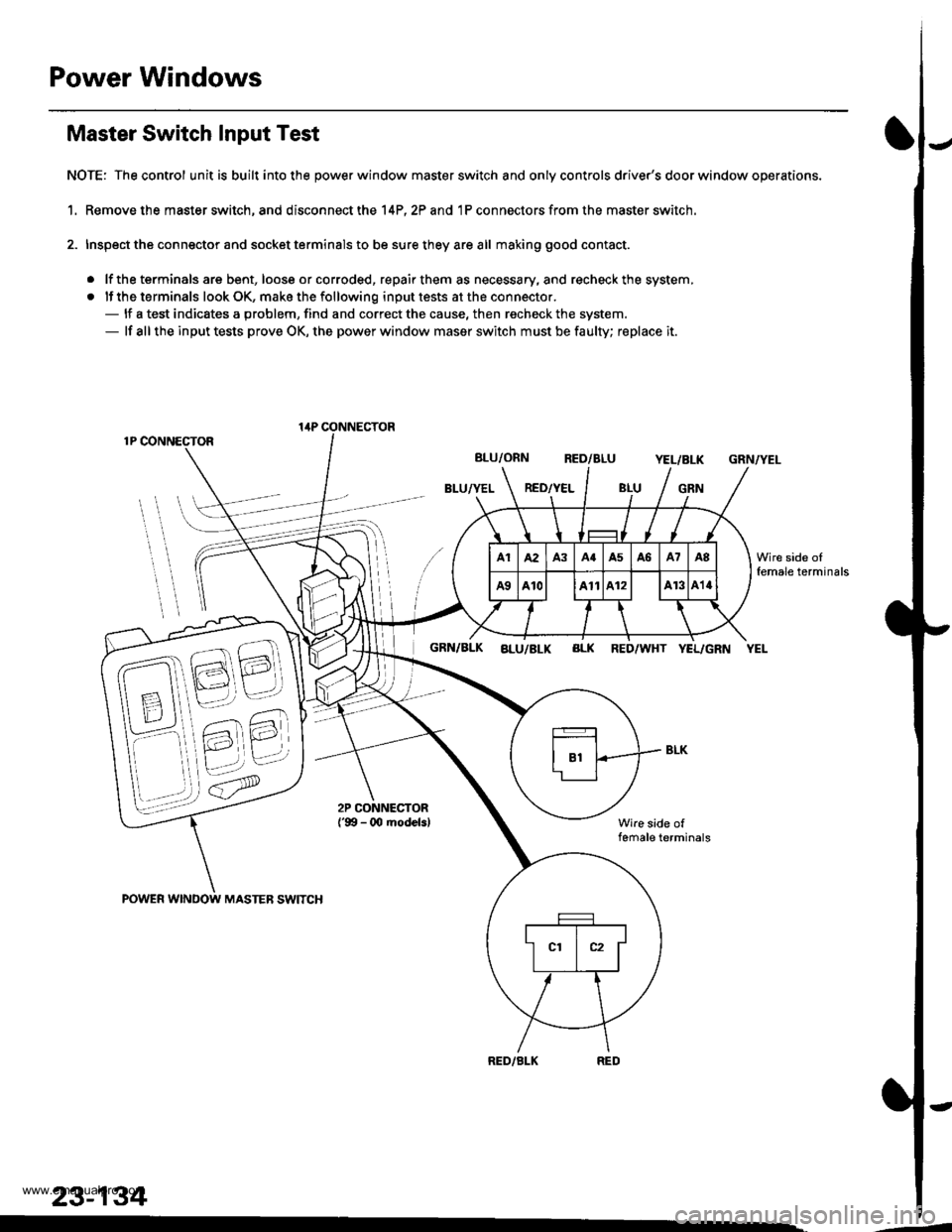
Power Windows
Master Switch Input Test
NOTE: The control unit is built into the power window master switch and only controls driver's door window operations.
1. Remove the master switch, and disconnect the 14P,2? and 1P connectors from the master switch.
2. Inspect the connector and socket terminals to be sure they are all making good contact.
. lf the terminals are bent, loose or corroded, repair them as necessary, and recheck the system,
. lf the terminals look OK, make the following input tests at the connector.- lf a test indicates a problem, find and correct the cause, then recheck the system.- lf all the input tests prove OK, the power window maser switch must be faulty; replace it.
1P CONNECTOR
BLU/ORN RED/BLUYEL/BLK
BLU/YEL RED/YELGRN
GRN/YEL
POWER WINDOW MASTEB SWITCH
GRN/BLK aLu/BLK BLK RED/WHT YEL/GRN YEL
Wire side offemale terminals
RED/BLK
lirP CONNECTOR
23-134
Wire side oIfemale terminals
.-
www.emanualpro.com