Adjust Ac HONDA CR-V 1999 RD1-RD3 / 1.G Workshop Manual
[x] Cancel search | Manufacturer: HONDA, Model Year: 1999, Model line: CR-V, Model: HONDA CR-V 1999 RD1-RD3 / 1.GPages: 1395, PDF Size: 35.62 MB
Page 1004 of 1395
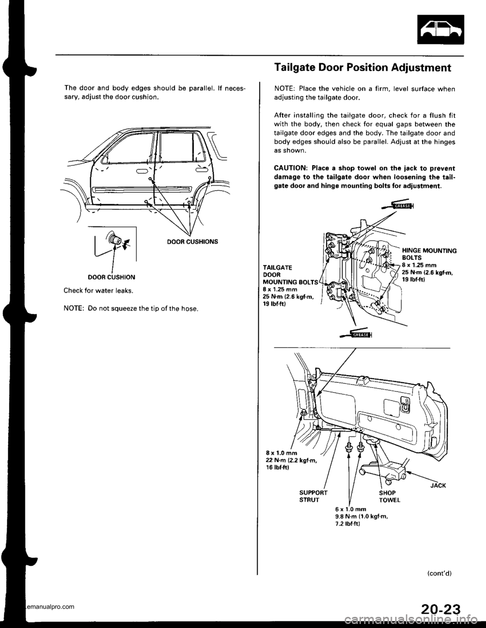
The door and body edges should be parallel. lf neces-
sary, adjust the door cushion.
ry.DOOR CUSHION
Check for water leaks.
NOTE: Do not squeeze the tip ofthe hose.
oooR cusHroNs
Tailgate Door Position Adjustment
NOTE: Place the vehicle on a firm, level surface when
adjusting the tailgate door.
After installing the tailgate door. check for a flush fit
with the body, then check for equal gaps between the
tailgate door edges and the body. The tailgate door and
body edges should also be parallel. Adjust at the hinges
as snown.
CAUTION: Place a shop towel on the iack lo prevent
damage to the tailgale door when loos€ning the tail-
gate door and hinge mounting bolts for adiustment.
TAILGATEDOORMOUNTING sOLTS8 x 1.25 mm25 N.m {2.6 kgf.m,19 tbf.ft)
HINGE MOUNYINGBOLTS8 x 1.25 mm25 N.m 12.6 kgt m,19 rbf.ftl
8x1.0mm22 N'rrl� 12.2 kgl.m,16 tbt.ftl
6xl.0mm9.8 N.m {1.0 kgt m,1.2 tbl.ltl
(cont'd)
20-23
www.emanualpro.com
Page 1005 of 1395
Doors
(cont'd)
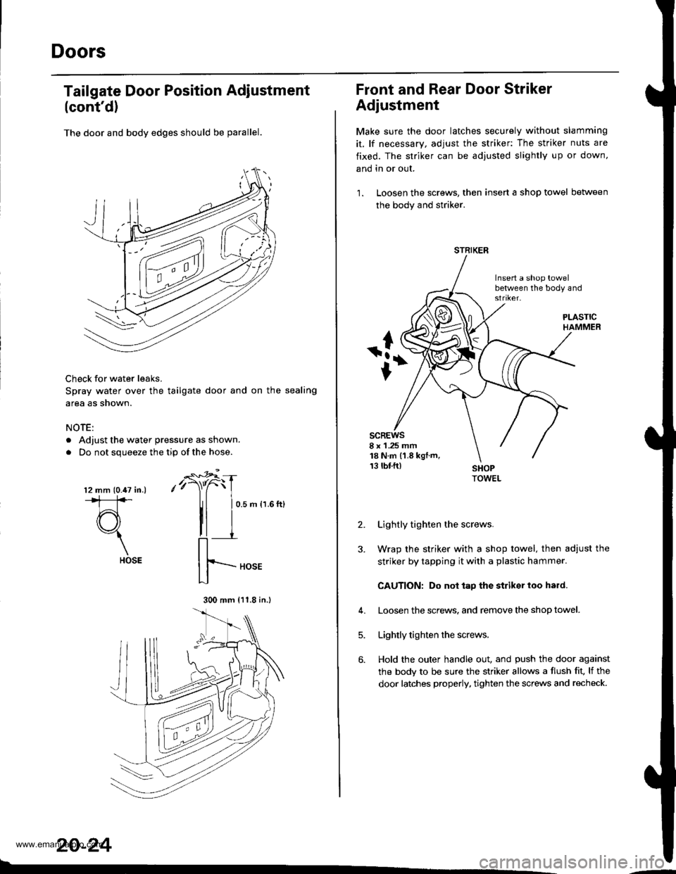
The door and body edges should be parallel.
Check for water leaks.
Spray water over the tailgate door and on the sealing
area as shown.
NOTE:
. Adjust the water pressure as shown.
. Do not squeeze the tip ofthe hose.
Tailgate Door Position Adiustment
-€*4
,'r)"C
II
0.5 m {1.6 ft}
20-24
l2 mm (0.47 in.).*1:]*
d3"1
HOSE
300 mm {11.8 in.l
Front and Rear Door Striker
Adjustment
Make sure the door latches securely without slamming
it, lf necessary, adjust the striker: The striker nuts are
fixed. The striker can be adjusted slightly up or down,
and in or out.
1. Loosen the screws, then insert a shop towel between
the body and striker.
Insert a shop towelbetween the body and
scREws8 x 1 .25 mm18 N.m (1.8 kgt.m,13 rbf.ft)
2.
J.
Lightly tighten the screws.
Wrap the striker with a shop towel, then adjust the
striker by tapping it with a plastic hammer.
CAUTION: Do not tap the striksr loo hard.
Loosen the screws. and remove the shop towel.
Lightly tighten the screws.
Hold the outer handle out, and push the door against
the body to be sure the striker allows a flush fit, lf the
door latches properly. tighten the screws and recheck.
4.
5.
6.
STRIKER
www.emanualpro.com
Page 1006 of 1395
Tailgate Door Striker Adjustment
Make sure the door latches securely without slamming
it. lf necessary, adjust the striker: The striker nuts are
fixed. The striker can be adjusted slightly up or down,
and in or out.
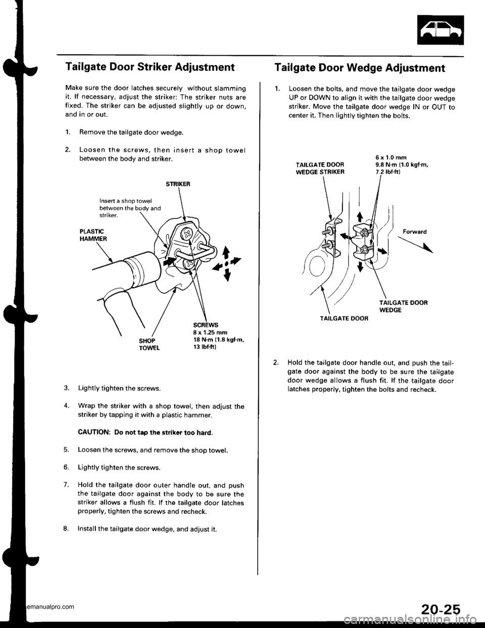
1. Remove the tailgate door wedge.
2. Loosen the screws, then insert a shop towel
between the body and striker.
8 x 1.25 mm18 N.m (1.8 kgf.m,r 3 tbf.ft)
1.
4.
Lightly tighten the screws.
Wrap the striker with a shop towel, then adjust the
striker by tapping it with a plastic hammer.
CAUTION: Do not tap the striker too hard.
Loosen lhe screws, and remove the shop towel.
Lightly tighten the screws.
Hold the tailgate door outer handle out, and push
the tailgate door against the body to be sure thestriker allows a flush fit. lf the tailgate door latchesproperly, tighten the screws and recheck.
Install the tailgate door wedge, and adjust it.
STRIKER
Insen a shoptowelbetween the body and
Tailgate Door Wedge Adjustment
1. Loosen the bolts, and move the tailgate door wedge
UP or DOWN to align it with the tailgate door wedge
striker. Move the tailgate door wedge lN or OUT to
center it. Then lightly tighten the bolts.
TAILGATE OOOR
Hold the tailgate door handle out, and push the tail-gate door against the body to be sure the tailgate
door wedge allows a flush fit. lf the tailgate door
latches properly, tighten the bolts and recheck.
Forward
20-25
www.emanualpro.com
Page 1014 of 1395
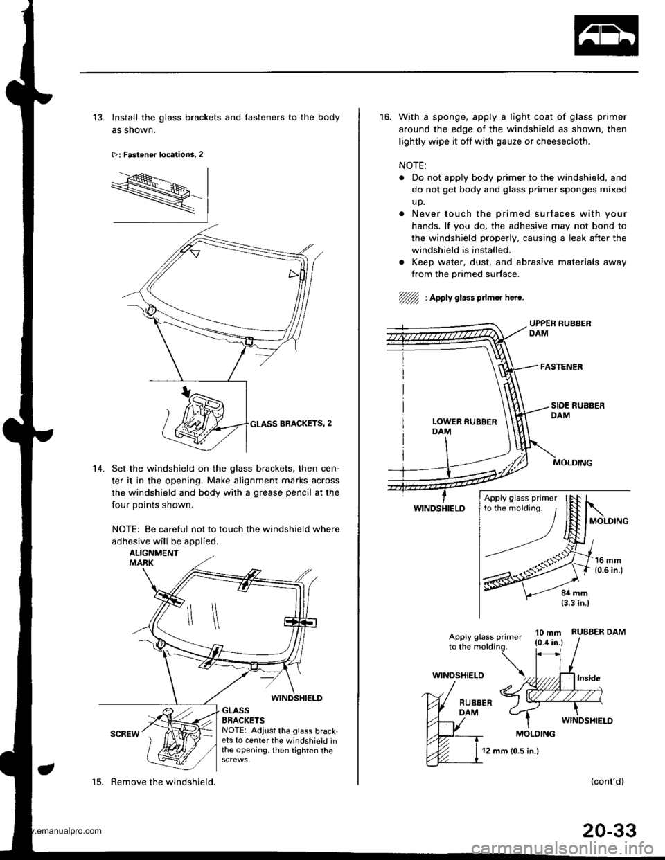
'13. Install the glass brackets and fasteners to the body
as shown.
>: Fastener locations, 2
R-
14. Set the windshield on the glass brackets. then cen
ter it in the opening. Make alignment marks across
the windshield and body with a grease pencil at the
four points shown.
NOTE| Be careful not to touch the windshield where
adhesive will be applied.
ALIGNMENTMABK
WINDSHIELD
GLASSBRACKETSNOTE: Adjust the glass brack-ets to center the windshield inthe opening, then tighten the
15. Remove the windshield.
12 mm 10.5 in.)
16. With a sponge, apply a light coat of glass primer
around the edge of the windshield as shown, then
lightly wipe it off with gauze or cheesecloth.
NOTE:
Do not apply body primer to the windshield, and
do not get body and glass primer sponges mixed
up.
Never touch the primed surfaces with your
hands. lf you do, the adhesive may not bond to
the windshield properly, causing a leak after the
windshield is installed.
. Keep water, dust, and abrasive materials away
from the primed surface.
//fu : Apply glass ptimar hea.
WINDSHIELD
10 mm{0.4 in.}RUBBER DAMApply glass primerto the molding.
(cont'd)
20-33
Apply glass primer
WINDSHIELD
MOLDING
www.emanualpro.com
Page 1041 of 1395
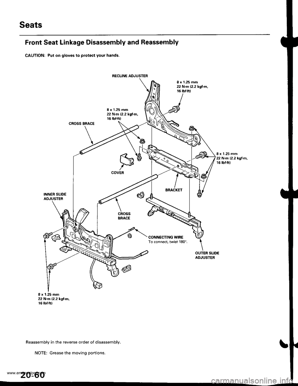
Seats
RECUNE ADJUSTER
Front Seat Linkage Disassembly and Reassembly
CAUTION: Put on gloves to protect your hands.
8 x 1 .25 mm22 N.m 12.2 kgl.m,16 tbf.fi)
8 x 1.25 mm22 N.m 12.2 kd-m,16 tbtf0
CROSS BRACE
8 x 1.25 mm22 N.m 12.2 kgl.m,16 tbf.f0
INNER SLIDEADJUSTER
8 x 1.25 mm22 N.rn l.2.2 kgl-m,16 rbr.ft)
CONNECTING WIRETo connect, twist 180".
cRossBRACE
OUTER SLIDEAOJUSTER
Reassembly in the reverse order of disassembly.
NOTE: Grease the moving portions.
20-60
www.emanualpro.com
Page 1049 of 1395
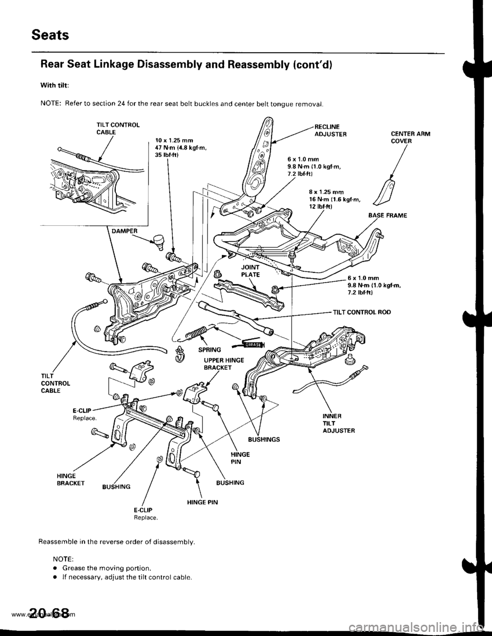
Seats
Rear Seat Linkage Disassembly and Reassembly (cont'd)
with tilt:
NOTE: Refer to section 24 for the rear seat belt buckles and center belt tongue removal
TILT CONTFOLCABLE10 x 1.25 mm47 N.m {i1.8 kgt.m,35 tbf.ft)
ARM
6x1.0mm9.8 N.m n.0 kgt.m,7.2 tbt.tll
CENTEBCOVER
/
n
//-)
ASE FRAME
8 r 1.25 mm16 N.m (1.6 kgf.m,12 tbt.ftl
DAMPER
6x1.0mm9.8 N.m 11.0 kgtm,7.2 tbttr)
TILT CONTROL ROD
A
@
SPRING
UPPER HINGE
TILTCONTROLCABLE
Replace.
q
BUSHING
E.CLIPReptace.
Reassemble in the reverse order of disassembly.
NOTE:
. Grease the moving ponion.
. lf necessary, adjust the tilt control cable.
20-64
HINGE PIN
www.emanualpro.com
Page 1054 of 1395
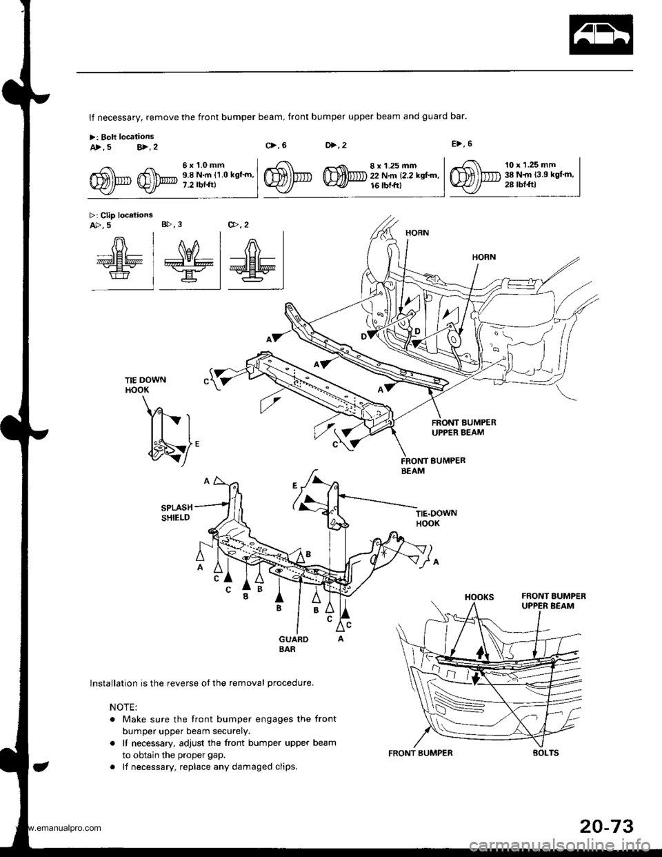
A>, 5 V.2
>: Clip locationsA>, 5 B>.3
lf necessary, remove the front bumper beam, front bumper upper beam and guard bar.
>: Boh locationsc>.6D>,2E>,6
TIE DOWNHOOK
Yl- r
{to/
Installation is the reverse ot the removal procedure.
NOTE:
. Make sure the front bumper engages the front
bumper upper beam securely.
. It necessary, adjust the front bumper upper beam
to obtain the proper gap.
. lf necessary, replace any damaged clips.
Gfu @p;i,li',ll-"-'
TIE.DOWNHOOK
v1
10 x 1.25 mm38 N.rn {3.9 kgf.m,28 rbl.ftl
@,,2
nln-nlznr I
dE6 I #\Er+ | ;lHl= |€ =.=r t:Wl
BEAM
FRONT BUMPEB
20-73
www.emanualpro.com
Page 1056 of 1395
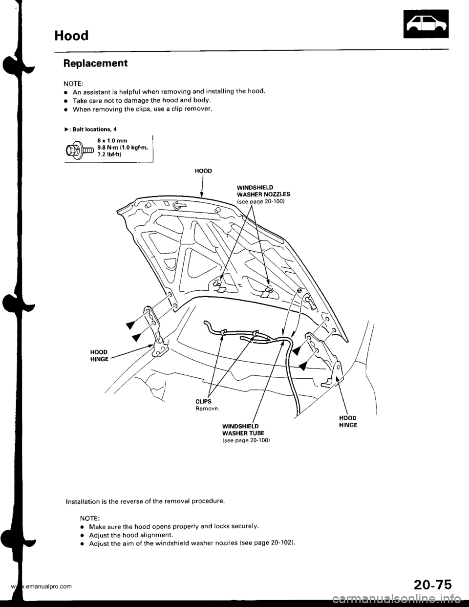
Hood
Replacement
NOTE:
. An assistant is helpful when removing and installing the hood.
a Take care not to damage the hood and body
. When removing the clips, use a clip remover.
>: Bolt locations, 4
6x1.0mm9.8 N.m {1.0 kgt.m,7.2 tbtfr)
WINDSHIELDWASHER NOZZLES(see page 20-100)
G
{
\HOODHINGEWINDSHIELDWASHER TUBE(see page 20-100)
Installation is the reverse of the removal procedure
NOTE:
. Make sure the hood opens properly and locks securely.
. Adjust the hood alignment.
. Adjust the aim of the windshield washer nozzles (see page 20-102)
HOOD
20-75
www.emanualpro.com
Page 1057 of 1395
Hood
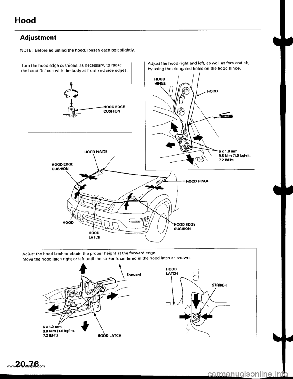
Adjustment
NOTE: Before adjusting the hood, loosen each bolt slightly.
Turn the hood edge cushions, as necessary, to make
the hood fit flush with the bodv at front and side edges.
f
sz
+
14---+ik-
HOOD EDGECUSHION
Adiust the hood latch to obtain the proper height at the forward edge'
Move the hood latch right or left until the striker is centered in the hood latch as shown
HOOD HINGE
\
?--
HOODLATCH
9.8 N.m (1.0 kgf m,
7.2 rbf.ftlHOOD LATCH
20-76
Adjust the hood right and left, as well as fore and aft,
by using the elongated holes on the hood hinge
6x1.0mm9.8 N.m (1.0 kgtm,7 .2 tbt.ttl
HOOD HINGE
www.emanualpro.com
Page 1059 of 1395
Rear Hatch Glass
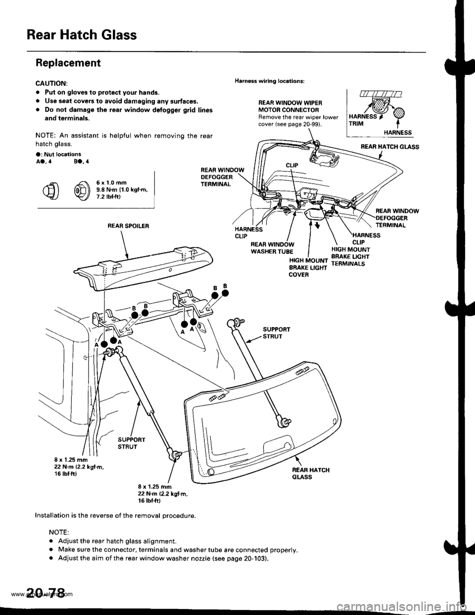
Replacement
CAUTION:
. Put on gloves to protecl your hands.
. Use seal covers to avoid damaging any surfaces.. Do not damage the rear window delogger grid lines
and terminals.
NOTE: An assistant is helpful when removing the rear
hatch glass.
a: Nul locationsAa.4 Ba.4
€ @ i!iff*-"-
Harnoss wiring locations:
REAR WINDOW WIPERMOTOR CONNECTORRemove the rear wiper lowercover (see page 20-99i.
HARNESS 'TRIM
.;=-
8 x 1.25 mm22 N-m l'2.2 kgl.m,'16 tbt fr)
8 x 1.25 mm22N.m l.2.2*ql.m,16 tbf.ft|
Installation is the reverse of the removal orocedure.
NOTE:
. Adjust the rear hatch glass alignment.
. Make sure the connector, terminals and washer tube are connected properly.
. Adjust the aim of the rear window washer nozzle (see page 20-103).
20-78
REAR SPOILER
'--
www.emanualpro.com