Valve HONDA CR-V 1999 RD1-RD3 / 1.G Workshop Manual
[x] Cancel search | Manufacturer: HONDA, Model Year: 1999, Model line: CR-V, Model: HONDA CR-V 1999 RD1-RD3 / 1.GPages: 1395, PDF Size: 35.62 MB
Page 591 of 1395
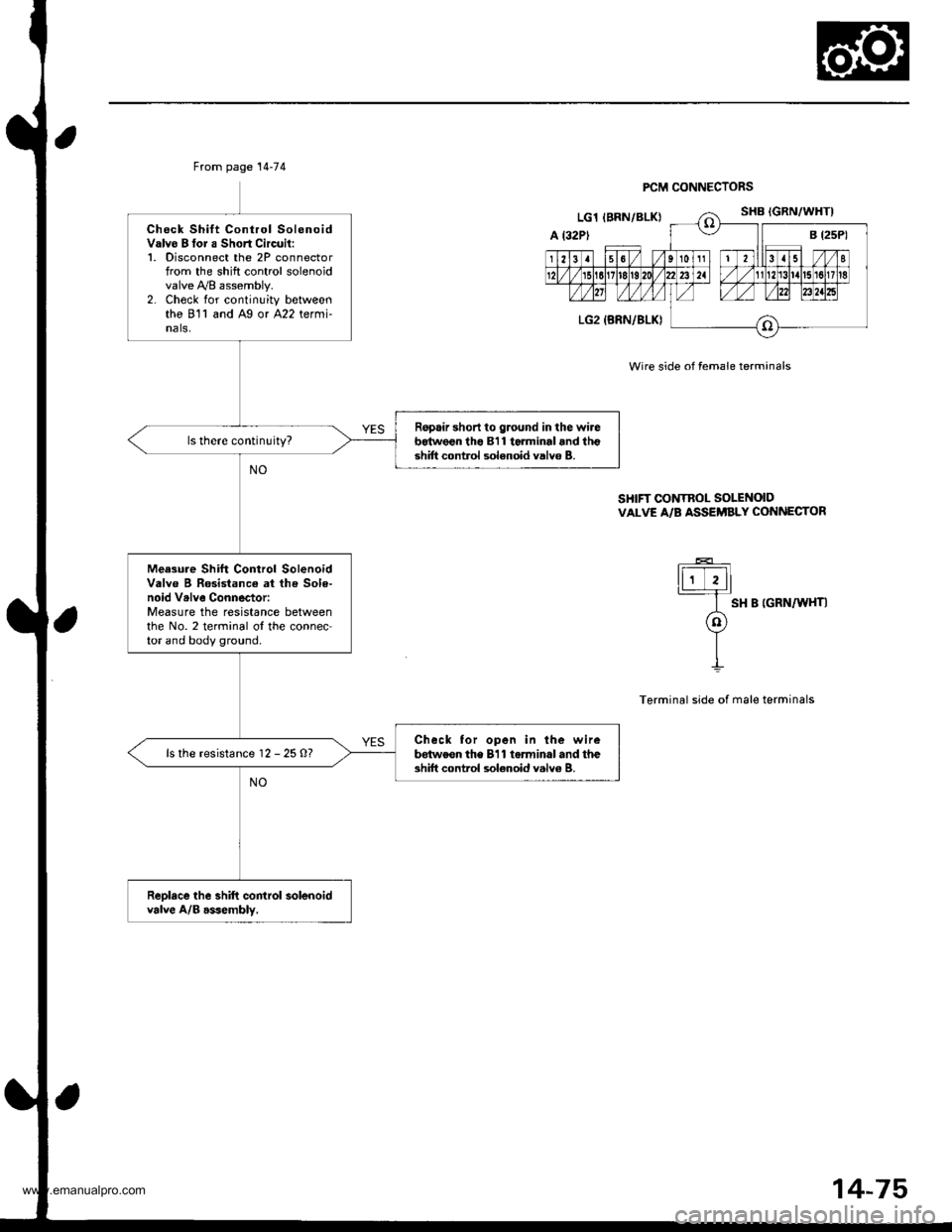
From page 14-74
Check Shift Control SolenoidValvo B tor a Short Circuil:1. Disconnect the 2P connectorfrom the shift control solenoidvalve y'y'8 assembly.2. Check for continuity betweenthe 811 and Ag or A22 termi-nals,
Ropair short to ground in the wireb64w€€n tho 811 torminal and lhgshift control solenoid valvo B.
Meesure Shift Control SolenoidValve B Rosistance at lh€ Sole-noid Vrlve Connector:Measure the resistance betweenthe No. 2 terminal ol the connector and body ground.
Check tor open in the wirebdtweon the 811 torminal and theshift control sol€noid valv6 B.ls the resistance 12 - 25 O?
Reolace the shift control solenoidvalve A/B asJembly,
PCM CONNECTORS
Wire side of female terminals
SHIFT CONTROL SOLENOIDVALVE A/B ASSEi'BLY CONNECTOR
ti;Tll
I sH B |GRN/W{T|
o
YII
Terminal side of male terminals
14-75
www.emanualpro.com
Page 598 of 1395
Electrical Troubleshooting ('97 Model)
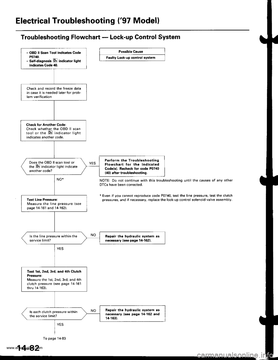
. OBD ll Scan Tool indicrt6 Cod6P0740.. Self-diagno3b E indicator lightindicatos Codc 40.
Check and record the freeze datain case it is needed laterlor prob-
lem verification
Check tor Another Code:Check whether the OBD ll scantool or the E indicator lightindicates another code.
Perlorm the TroubleshootingFlowchart lor th€ indicat€dCodo{s). Rocheck tor code P0740
{ilol after troubl$hooting.
Does the OBD ll scan tool orthe E indicator light indicateanother code?
Tesl Line Pressure:Measure the line pressure (seepage 14-161 and 14-162).
ls the line pressure within theservice limit?R6pair tho hydraulic ayst€m asnecessary {see page 14-162}.
Test lst, 2nd, 3rd, and 4th ClutchPressure:Measure the 1st, 2nd, 3rd, and 4thclutch pressure (see page 14161thru 14''163).
Repair the hydraulic system dsnecessary {see pago 14-152 rnd14-163).
ls each clutch pressure withinthe service limit?
Troubleshooting Flowchart - Lock-up Control System
Possiblo Cause
Faulty Lock-up control sy3t6m
NOTE: Do not continue with this troubleshooting until the causes of any otherDTCS have been corrected.
* Even if yotl cannot reproduce code P0740. test the line pressure, test the clutchpressures, and i{ necessary, replace the lock-up control solenoid valve assembly
1
To page 14-83
4-82
www.emanualpro.com
Page 599 of 1395
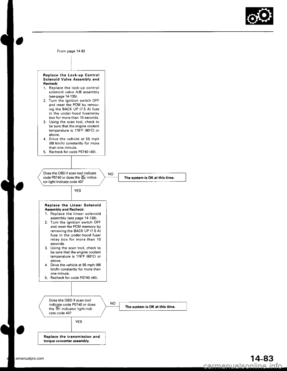
From page 14 82
Replace the Lock-up ControlSolenoid Valve Assembly andRecheck:1. Replace the lock-up controlsolenoid valve A/B assembly(see page 14-'135).2. Turn the ignition switch OFFand reset the PCM by remov-ing the BACK uP (7.5 A) fusein the under-hood fuse/relaybox for more than 10 seconds.3. lJsing the scan tool, check tobe sure that the engine coolanttemperature is 176"F 180'C) orabove,4. Drive the vehicle at 55 mph(88 km/h) constantly for moretnan one mrnute.5. Recheck for code P0740 (40).
Does the OBD ll scan tool indicatecode PO74O or doesthe El indicator light indicate code 40?The svstem is OK ai this time.
Replace the Linear Sol€noidA$embly and Recheck:'1. Beplace the linear solenoidassembly {see page 14-138).2. Turn the ignition switch OFFand reset the PCM memory byremoving the BACK UP (7.5 A)fuse in the underhood fuse/relay box for more than 10seconds.3. Using the scan tool, check tobe sure that the engine coolanttemperature is 176"F (80'C) orabove.4. Drive the vehicle at 55 mph (88
km/h) constantly for more thanone minute,5. Recheck for code P0740 {40).
Does the OBD ll scan toolindicate code P0740 or doesthe E indicator light indicate code 40?
The svsteo is OK at this tim€.
Replace the transmission andtorque convertor assembly.
www.emanualpro.com
Page 600 of 1395
Electrical Troubleshooting ('97 Model)
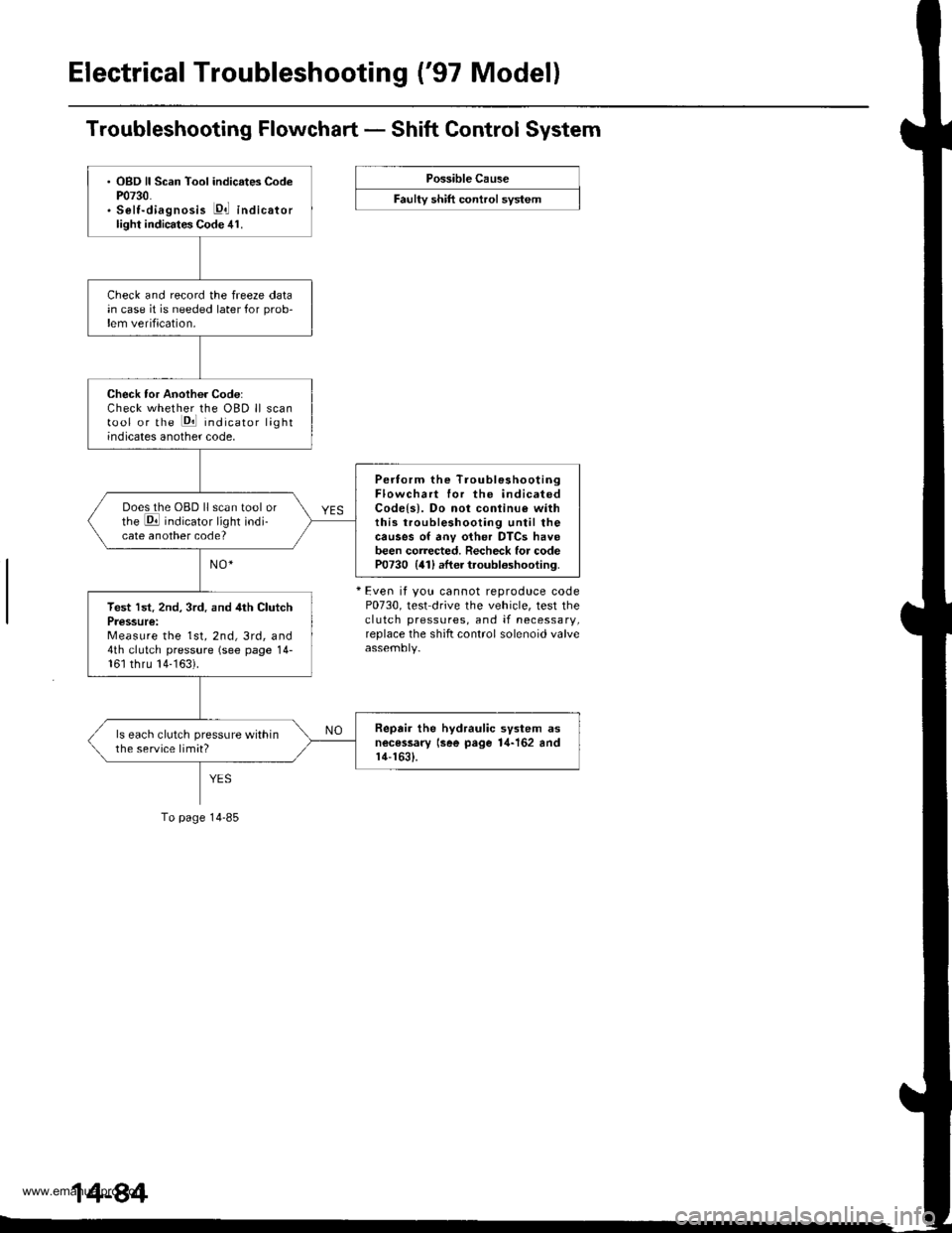
Troubleshooting Flowchart - Shift Control System
Possible Cause
F""lty "t lft ".tttr"l "y"t..
+ Even it you cannot reproduce codeP0730, test drive the vehicle, test theclutch pressures, and if necessary,replace the shift control solenoid valve
. OBD ll Scan Tool indicates CodeP0730.. Selt-diagnosis E,l indicatorlight indicates Code 41.
Check and record the freeze datain case it is needed later for prob-lem verification.
Check tor Another Code:Check whether the OBD ll scantool or the Pll indicator lightindicates another code,
Pertorm the TroubleshootingFlowchart for the indicatedCodels). Do not conlinu€ withthis troubleshooting until thecauses of anv other DTCS havebeen corrected. Recheck for codeP0730 {41) after troubloshooting.
Does the OBD ll scan tool orthe E indicator light indi-cate another code?
Test lst. 2nd, 3rd. and 4th ClutchPressure:Measure the 1st, 2nd, 3rd, and4th clutch pressure (see page 14-161 thru 14-163).
Repair the hydraulic svstem asnecessary lsee page 1,1-162 andr4-1631.
ls each clutch pressure withinthe service limit?
To page 14-85
www.emanualpro.com
Page 601 of 1395
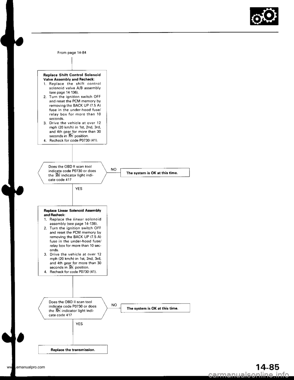
Replace Shift Control Solenoidvslve Assembly and Recheck:1. Replace the shift controlsolenoid valve A/B assembly(see page'14 136).2. Turn the ignition switch OFFand reset the PCM memory byremoving the BACK UP (7.5 A)fuse in the under-hood fuse/relay box for more than 10seconds.3. Drive the vehicle at over 12mph (20 km/h) in 1st,2nd,3rd,and 4th qear for more than 30seconds in E position.
4. Recheck for code P0730 (41).
Does the OBD ll scan toolindicate code P0730 or doesthe E indicator light indicate code 41?
The svstem is OK at this time.
Replace Linea. Solenoid Ass€mblyand Recheck:1. Replace the linear solenoidassembly lsee page 14-138).2. Turn the ignition switch OFFand reset the PcM memory byremoving the BACK UP 17.5 A)fuse in the underhood fuse/relay box tor more than 10 sec'onos.3. Drive the vehicle at over '12
mph {20 km/h) in 1st,2nd,3rd,and 4th geal for more than 30seconds in -Da position.
4. Recheck for code P0730 (41).
Does the OBD llscan toolindicate code P0730 or doesthe Di indicator light indi-cate code 41?
The syslem is OK at this time.
From page 14-84
14-85
www.emanualpro.com
Page 609 of 1395
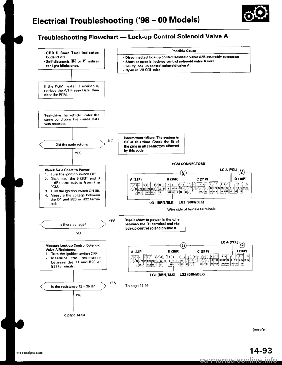
Electrical Troubleshooting ('98 - 00 Models)
Troubleshooting Flowchart - Lock-up Control Solenoid Valve A
Poslible Cause
. Dbconnected lock-up control solenoid valve A/B assemblY connector. Short or open in lock-up control solenoid valve A wire. Faulty lock-up control solenoid valve A' Open in vB SOL wire
LGI|BRN/BLK) LG2IBRN/BLK)
To page 14 95
(cont'd)
14-93
A t32Pli r rriltI l,1 I I ltDrste,0n,,2. t3r B'r!51 r.
LGl IBRN/BLKI LG2 (BRN/BLKI
Wire side of female terminals
A {32P)
.OBD ll Scan Tool indicatesCode Pl753.. Self-di.gnosis E or E indica-
tor light blinks once.
lf the PGM Tester is available,retrieve the M Freeze Data, then
clear the PCM.
Test-drive the vehicle under the
same conditions the Freeze Data
lntermittent failul.. The system is
OK at this time. Check the fit of
the Din3 in all connectors affected
by thb code.
Did the code return?
Check for a Short to Power:'1. Turn the ignition switch OFF.
2. Disconnect the B (25P) and D(16P) connectors trom thePCM,3. Turn the ignition switch ON (ll).
4. Measlre the voltage betweenthe D1 and 820 or 822 termi-nals,
n€pair short lo power in the wire
betw€€n the Dl terminal and the
lock-up control solenoid valve A
Mg.sure Lock-up Control SolenoidValve A Rssistance:1. Turn the ignition switch OFF.2. M easu re the resistancebetween the D1 and 820 or822 terminals.
ls the resistance 12 - 25 o?
To page 14-94
www.emanualpro.com
Page 610 of 1395
Electrical Troubleshooting ('98 - 00 Models)
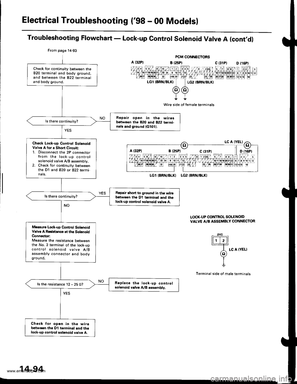
Troubleshooting Flowchart - Lock-up Control Solenoid Valve A (cont'dl
FCM CONNECTORS
B {25P} C t31Pl
Wire side ot female terminals
LGlIARN/ALKI LG2IBRN/BLKI
LOCK-UP CONTROL SOLENOIDVALVE A/B ASSEMBLY CONNECTOR
tFttl._T=
A LC A (YELI(o)Y
I
Terminal side of male terminals
From page 14-93
Check tor continuity between theB20 terminal and body ground,and between the 822 terminaland body ground.
Ropair open in the wire3b€tweon tha 820 and 822 termi-nals and ground lG101l.
Ch6ck Lock-up Control SolonoidValv6 A tor a Short Ci.cuit:'1. Disconnect the 2P connectorfrom the lock up controlsolenoid valve A/B assembly.2. Check for continuity betweenthe Dt and B2O or 822 te(minals.
Ropai. lhort to g.ound in the wireb€twe€n the Dl terminal and thelock-up control solonoid vslvg A.
Mersurg Lock-up Co|ttrol SolonoidValvo A Rolktanco at tho SolonoidConnoctor:Measure the resistanco betweenthe No. 2 terminal of the lock,upcontrol soleno;d valve A/Bassembly connector aod bodyground.
Replace the lock-up controlsolonoid vrlve A/B a$ambly,ls the resistance 12 - 25 0?
Chsck for open in th€ wircbctwe€n tho Dl terminal lnd th6lock-up cont.ol solonoid v.lve A.
a t32P)D l16Pl
a l32Plc t3lPl
14-94
www.emanualpro.com
Page 612 of 1395
Electrical Troubleshooting ('98 - 00 Models)
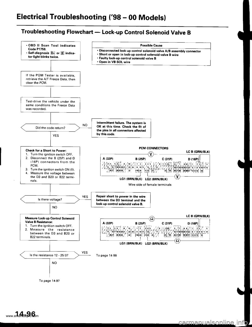
Troubleshooting Flowchart - Lock-up Control Sotenoid Valve B
Possibl€ Cause
. Disconnected lock-up control solenoid valve A/8 assembly connector. Short or open in lock-up control solenoid valve B wire. Fauhy lock-up control solenoid valve B. Open in VB SOL wir€
PCM CONNECTORSLC B {GRN/8LKI
LG1{BRN/BLK} I-G2{BRN/BLK)
Wire side of female terminals
A {32P1
To page 14 98
.OBD ll Scan Tool indicatesCode P'l758.. Sell-diagnosis Dl or E indica-tor light blinks twic€.
lf the PGM Tester is available,relrieve the A,/T Freeze Data, thenclear the PCM-
Test-drive the vehicle under thesame conditions the Freeze Data
Interm ittant tailure. The lystem isOK at this time. Check the tii ottho pin3 in all connectors athedby this code.
Did the code return?
Check for a Short to Pow€r:1. Turn the ignition switch OFF.2. Disconnect the B 125P) and D(16P) con nectors lrom thePCM.3. Turn the ignition switch ON 1ll).4. Measure the voltage betlveenthe D3 and 820 or 822 termi-nals.
Repair shon to power in the wirebetween tho D3 terminal and thelook-up control solenoid valve B.
Measure Lock-up Control SolanoidValve B Resistanc€:1. Turn the ignition switch OFF.2. Measure the resistancebetween the D3 and 820 or822 terminals.
ls the resistance 12 - 25 O?
To page 14-97
www.emanualpro.com
Page 613 of 1395
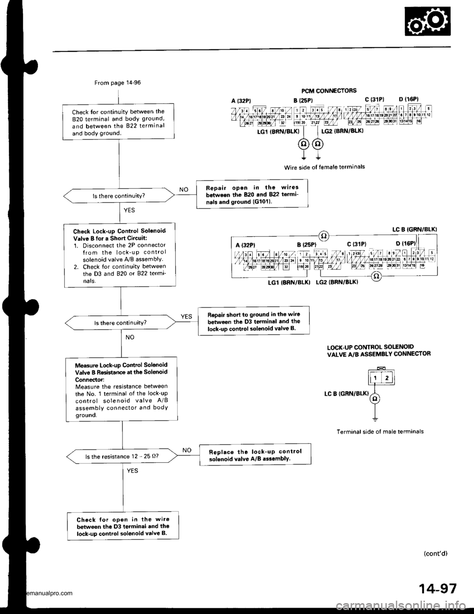
From page 14-96
Check Ior continuity betlveen the
B2O terminal and body ground,
and between the 822 terminal
and body ground.
Bepair open in the wirea
between the 820 and 822 te.mi-
nals and ground (G1011.
Check Lock-up Control Solenoid
Valve I fo. a Short Circuit:1. Disconnect the 2P connectorfrom the lock_u p control
solenoid valve A,/B assembly2. Check for continuity betweenthe D3 and 820 or 822 termi
nats.
Rep.ir short to ground in the wiie
between the D3 terminal and the
lock-uD control solenoid valve B.ls there continuity?
Measure Lock-up Control Solenoid
valve B Resistance at the solenoid
ConnedoMeasure the resistance between
the No. 1 terminal of the lock_up
control solenoid valve A/B
assembly connector and bodYground.
Replace the lock_up conirol
solenoid valve A/8 a$embly.ls the resistance 12 - 25 O?
Check for open in the wiro
betwoen the D3 terminal and the
lock-up control solenoid valve B.
PCM CONNECTORS
B (25Pt c (31P1 D (16P1
rc1 rBRN/BLKk'
c$G2
{BRN/BLKI
t
Wire side ol female terminals
L(rcK.UP CONTROL SO1TNOID
VALVE A/B ASSEMBLY CONNECTOR
LC B IGRN/BLK)
(cont'd)
14-97
A {32P1
www.emanualpro.com
Page 614 of 1395
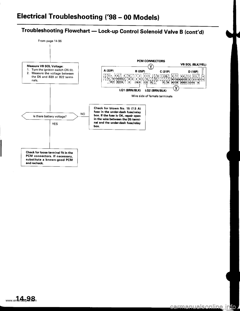
Electrical Troubleshooting ('98 - 00 Modelsl
Troubleshooting Flowchart - Lock-up Control Solenoid Valve B (cont,d)
From page 14 96
PCM CONNECTORSVB SOL (BLK/YEL}
LG1 (BBN/8LKI LG2 (BRN/BLKI
Wire side of Iomale terminals
Measuro VB SOL Voltago:1. Turn the ignition switch ON llt).2. Measure the voltage betlveenthe D5 and 820 or 822 terminals,
Check tor blown No. t5 (7.5 Alfuse in the underdash fu36/.elaybox. lf th6 fuse is OK, ..pair openin the wire betwooo tho D5 t.rmi-nel and thg underdash two/relayItox.
ls there battery voltage?
Check for loose terminal lit in thePCM connectors. ll n€ces3a.y,substitute a known-good pCM
and .€check.
A l32P)
14-98
www.emanualpro.com