Bolt HONDA CR-V 1999 RD1-RD3 / 1.G Workshop Manual
[x] Cancel search | Manufacturer: HONDA, Model Year: 1999, Model line: CR-V, Model: HONDA CR-V 1999 RD1-RD3 / 1.GPages: 1395, PDF Size: 35.62 MB
Page 946 of 1395
Brake Hoses/Lines
Hose Replacement
CAUTION: Do not spill brak€ fluid on the vehicl€; it m8y
damage th€ paint; if brak€ lluid doos contact tho paint,
wash it off immediately with water.
NOTE:
. Before reassembling, check that all pans are free of
dust and other foreign particles.
. Replace parts with new ones whenever specified to
qo so,
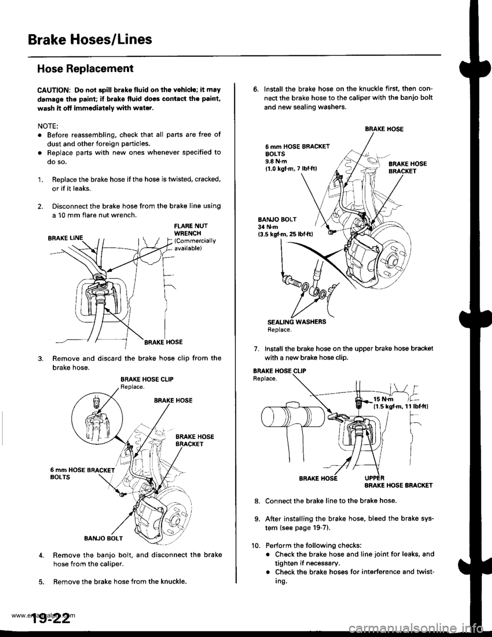
Replace the brake hose ifthe hose is twisted, cracked.
or if it leaks.
Disconnect the brake hose from the brake line using
a 10 mm flare nut wrench.
'1.
FLARE NUTWRENCH(Commercially
available)
BRAKE HOSE
Remove and discard the brake hose cliD from the
brake hose.
Remove the banjo bolt, and disconnect the brake
hose from the calioer.
5. Remove the brake hose from the knuckle.
19-22
6. Install the brake hose on the knuckle first, then con-
nect the brake hose to the caliper with the banjo bolt
and new sealing washers.
6 mm HOSE BRACKETEOLTS9.8Nm(1.0 kgf.m,7 lbf.ftlBRAKE HOSE
BANJO BOLT34 N.m
13.5 kgf.m, 25 lbl.ftl
SEALING WASHERSHeplace.
7. Installthe brake hose on the upper brake hose bracket
with a new b.ake hose clip.
Replace.
BRAKE HOSE ARACKET
Connect the brake line to the brake hose.
After installing the brake hose, bleed the brake sys-
tem (see page '19-7).
Perform the following checks;
. Check the brake hose and line joint for leaks, and
tighten if necessary.
. Check the brake hoses for interference and twist-
Ing
1 tbtftl
F
)
/
8.
9.
www.emanualpro.com
Page 981 of 1395
Pulsers/Wheel Sensors
Wheel Sensor Replacement
NOTE;
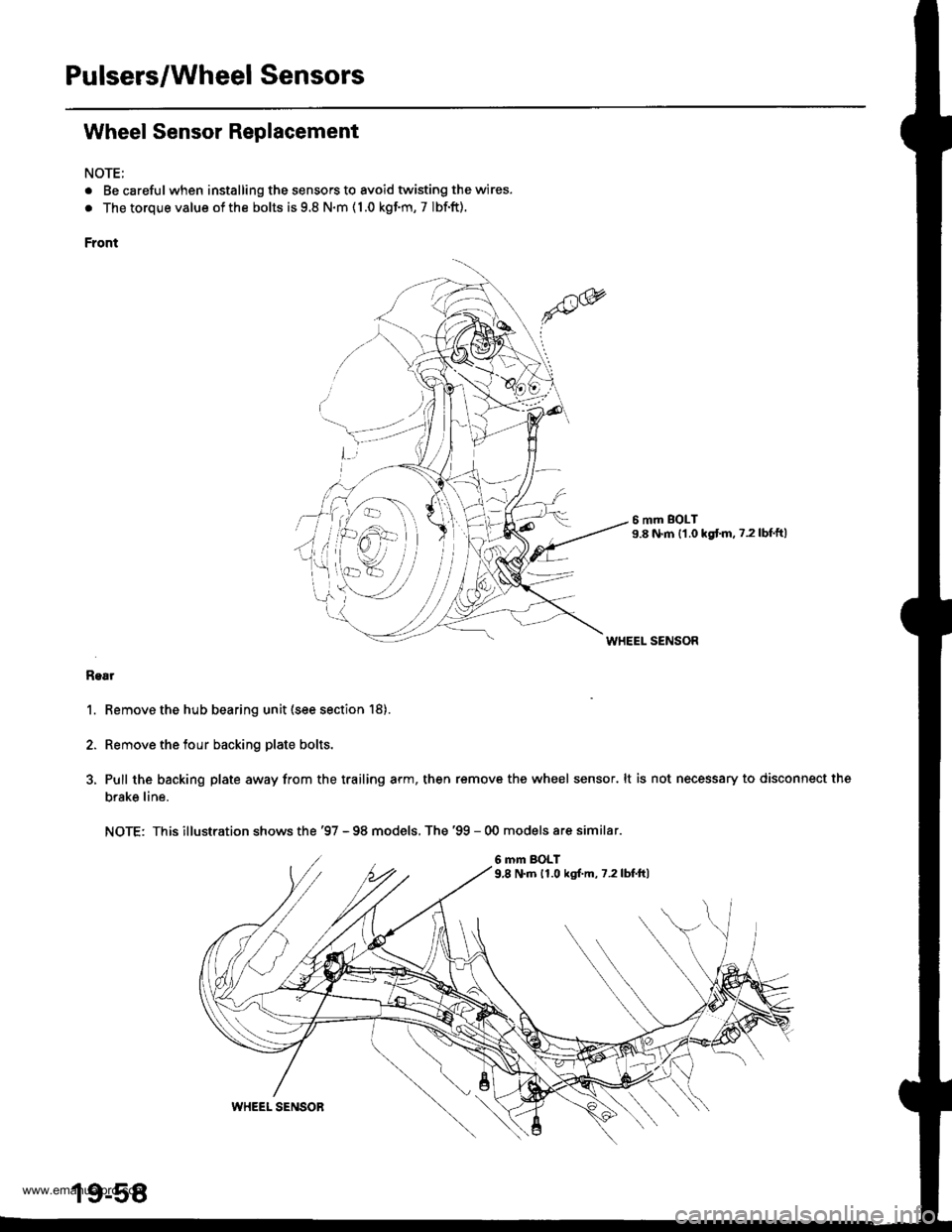
. Be carefulwhen installing the sensors to avoid twisting the wires.
. The torque value of the bolts is 9.8 N.m ( 1.0 kgf.m, 7 Ibf.ft).
Front
6 mm BOLT9.8 N.m {1.0 kgtm. ?.2lbf'ft)
WHEEL SENSOR
Rgar
1. Remove the hub bearing unit (see section 18).
2. Remove the tour backing plate bolts.
3, Pull the backing plate away from the trailing arm, then remove the wheel sensor. lt is not necessary to disconnect the
brake line.
NOTE: This illustration shows the '97 - 98 models, The '99 - 00 models are similar.
6 mm BOLT9,8 N.m 11.0 kgf.m, 7.2lbf.ft)
\all
19-58
WHEEL SENSOR
www.emanualpro.com
Page 989 of 1395
Doors
Front Door Outer Handle Replacement
CAUTION: Put on gloves to protect your hands.
NOTE; Raise the glass fully.
2.
1.Removel
. Door panel (see page 20-7). Plastic cover {see page 2O-2)
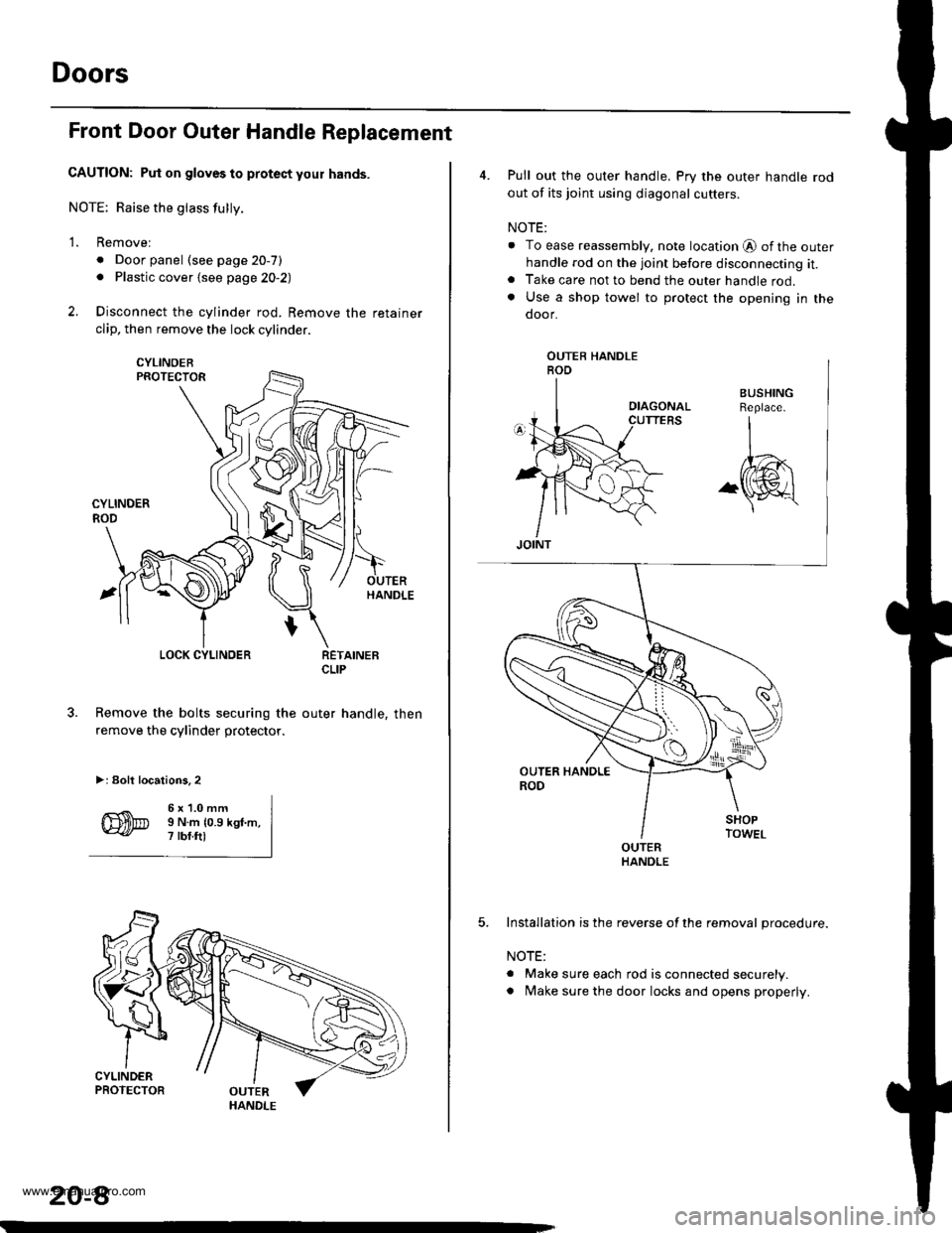
Disconnect the cylinder rod. Remove the retainer
clip, then remove the lock cylinder.
5.
6 x'1.0 mmI N.m {0.9 kgt.m,7 rbf.ftl
LOCK CYLINDER
Remove the bolts securing the
remove the cylinder protector.
>: Eolt locations,2
RETAINEBCLIP
outer handle, then
HANDLE
20-8
4. Pull out the outer handle, Pry the outer handle rod
out of its joint using diagonal cutters.
NOTE:
. To ease reassembly, note location @ ofthe outerhandle rod on the joint before disconnecting it.. Take care not to bend the outer handle rod.. Use a shop towel to protect the opening in the
door.
OUTEBHANDLE
5. Installation is the reverse of the removal procedure.
NOTE:
. Make sure each rod is connected securely.. Make sure the door locks and opens properly.
www.emanualpro.com
Page 990 of 1395
Front Door Latch Replacement
CAUTION: Put on gloves to protect your hands,
NOTEr Raise the glass fully.
'1. Remove:
. Door panel (see page 20-7)
. Plastic cover (see page 20-21
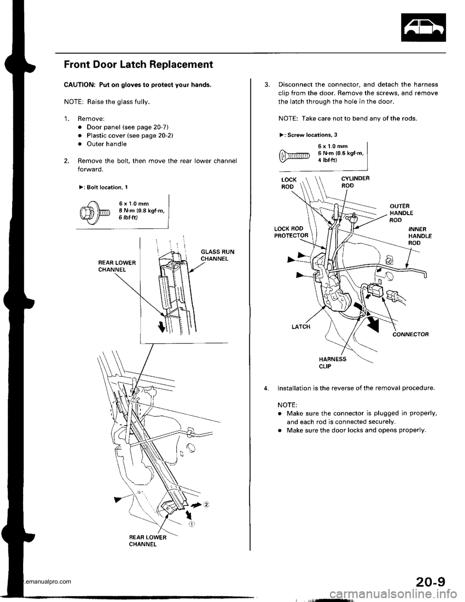
. Outer handle
2. Remove the bolt, then move the rear lower channel
forward.
>: Bolt location, 1
6xl.0mm8 N.m (0.8 kgf m,6 tbf ft)
3. Disconnect the connector, and detach the harness
clip from the door. Remove the screws, and remove
the latch through the hole in the door.
NOTE: Take care not to bend any of the rods.
>: Screw locations,3
6x1.0mm6 N.m 10.6 kgt m,4 tbf.ft)
CYLINDERROD
OUTERHANDLEROD
LOCK RODPROTECTOR
CONNECTOR
HARNESS
Installation is the reverse of the removal procedure.
NOTE:
. Make sure the connector is plugged in properly,
and each rod is connected securely.
a Make sure the door locks and opens properly.
CLIP
20-9
www.emanualpro.com
Page 991 of 1395
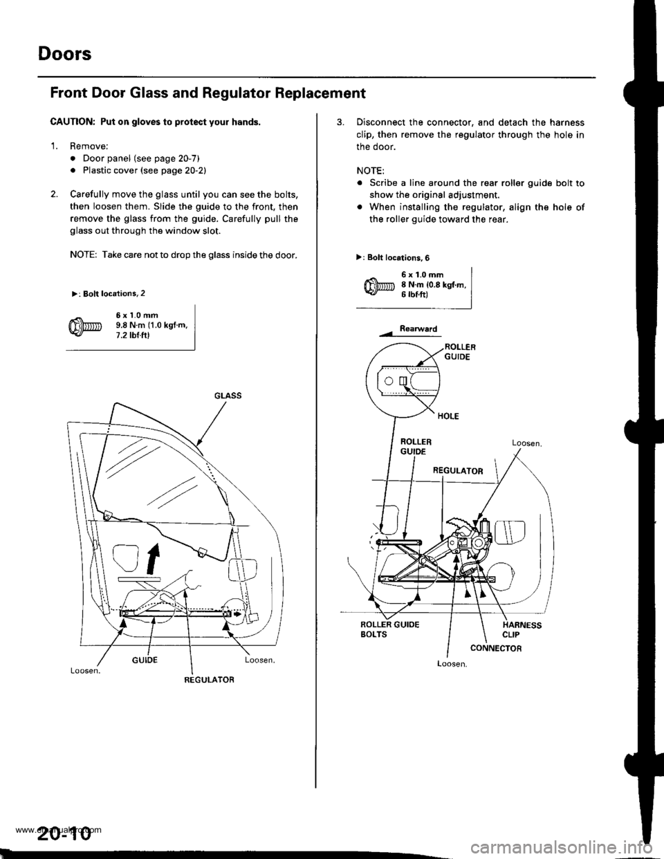
Doors
Front Door Glass and Regulator Replacement
CAUTION: Put on gloves to protect your hands,
1. Remove;
. Door panel (see page 20-7)
. Plastic cover (see page 20-21
2. Carefully move the glass until you can see the bolts,
then loosen them. Slide the guide to the front, then
remove the glass from the guide. Carefully pull the
glass out through the window slot.
NOTE: Take care not to drop the glass inside the door.
>: Bolt locations,2
6xl.0mm9.8Nm(1.0kgt.m.7.2 tbt.ftl
GLASS
REGULATOR
20-10
3. Disconnect the connector, and detach the harness
clip, then remove the regulator through the hole in
the door.
NOTE:
. Scribe a line around the rear roller guide bolt to
show the original adjustment.
. When installing the regulator, align the hole of
the roller guide toward th€ rear.
>: Bolt locations,6
6x1.0mm8 N.m {0.8 kgt.m,6 rbtft)
Roaru/ard
Loosen,
www.emanualpro.com
Page 993 of 1395
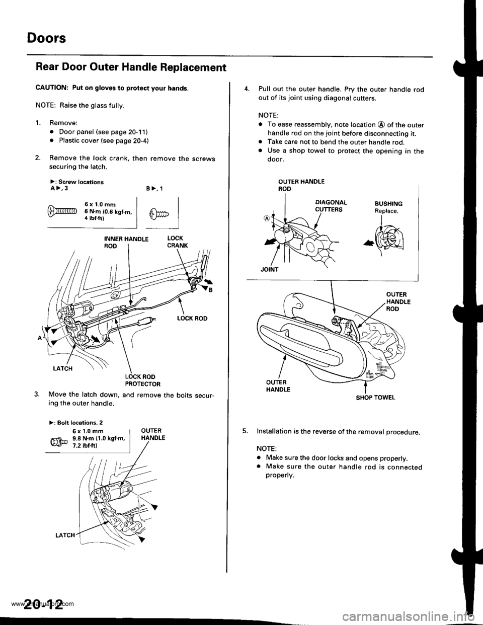
Doors
Rear Door Outer Handle Replacement
CAUTION: Put on gloves to protect your hands.
NOTE: Raise the glass fully.
1. Remove:
. Door panel (see page 20-11). Plastic cover (see page 20-4)
2. Remove the lock crank. then remove the screws
securing the latch.
>: Screw locationsA>.3
6x1.0mm6 N.m 10.6 kgf.m.4 tbf.ft)
B>,'l
^lPC tlTn-i I
LOCK RODPROTECTOR
and remove the bolts secur-Move the latch down,
ing the outer handle,
>: Bolt locations. 2
20-12
.
6x1.0mm9.8 N.m {1.0 kgf.m,7.2 rbf.ft)
4, Pull out the outer handle. Pry the outer handle rod
out of its joint using diagonal cutters.
NOTE;
o To ease reassembly, note location @ of the outerhandle rod on the joint before disconnecting it.. Take care not to bend the outer handle rod.. Use a shop towel to protect the opening in the
door.
5. Installation is the reverse ofthe removal procedure.
NOTE:
a Make sure the door locks and opens properly.. Make sure the oute. handle rod is connectedproperly.
OUTER HANDLEROD
SHOP TOWEL
www.emanualpro.com
Page 994 of 1395
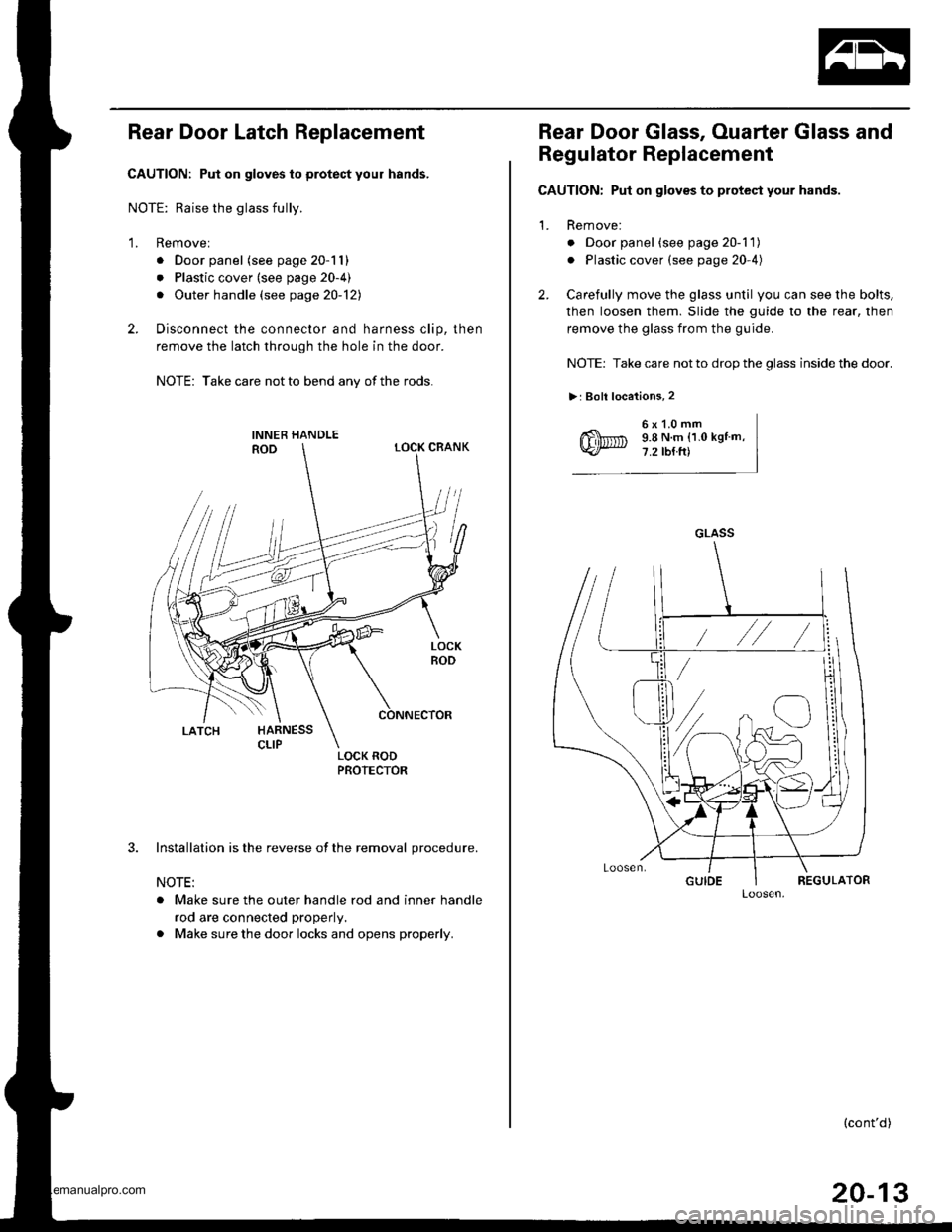
Rear Door Latch Replacement
CAUTION: Put on gloves to protect your hands,
NOTE: Raise the glass fully.
1. Removel
. Door panel (see page 20-11)
. Plastic cover (see page 20-4)
. Outer handle (see page 20-121
2. Disconnect the connector and harness clip, then
remove the latch through the hole in the door.
NOTE: Take care not to bend any of the rods.
3. Installation is the reverse of the removal procedure.
NOTE:
. Make sure the outer handle rod and inner handle
rod are connected properly.
. Make sure the door locks and opens properly.
Rear Door Glass, Ouarter Glass and
Regulator Replacement
CAUTION: Put on gloves to protect your hands.
1. Remove:
o Door panel (see page 20-1 1)
. Plastic cover (see page 20-4)
2. Carefully move the glass until you can see the bolts,
then loosen them. Slide the guide to the rear, then
remove the glass from the guide.
NOTE: Take care not to drop the glass inside the door.
>: Boll locations, 2
6x1.0mm9.8 N.m (1.0 kgtm,7.2 tb{ft)
GLASS
(cont'd)
20-13
www.emanualpro.com
Page 995 of 1395
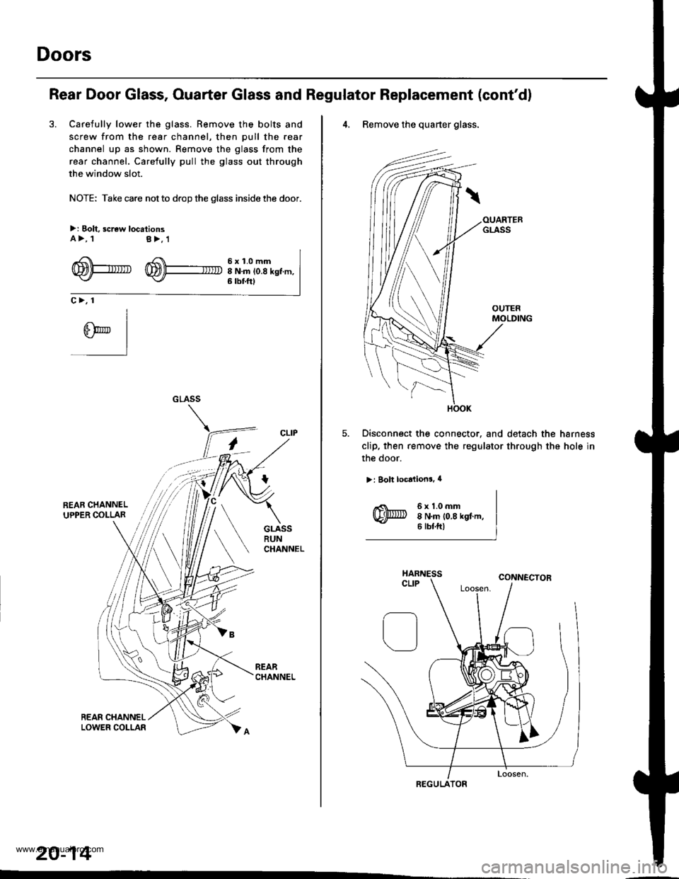
Doors
Rear Door Glass, Ouarter Glass and Regulator Replacement (cont'd)
3. Carefully lower the glass. Remove the bolts and
screw from the rear channel, then pull the rear
channel up as shown. Remove the glass from the
rear channel. Carefully pull the glass out through
the window slot.
NOTE: Take care not to drop the glass inside the door.
>: Bolt, screw locationsA>, tB>,1
-4 f 6 x 1.0 mmrTmtl-larR '^S\\\-.- -
WPU W)+ INmio.8ksf m,6 tbf.ftt
c>, 1
CLIP
20-14
''
4. Remove the quarter glass.
Disconnect the connector. and detach the harness
clip, then remove the regulator through the hole in
the door.
>: Bolt localions, 4
6x1.0mm8 N.m 10,8 kgf.m,6 tbtftl
REGULATOR
www.emanualpro.com
Page 996 of 1395
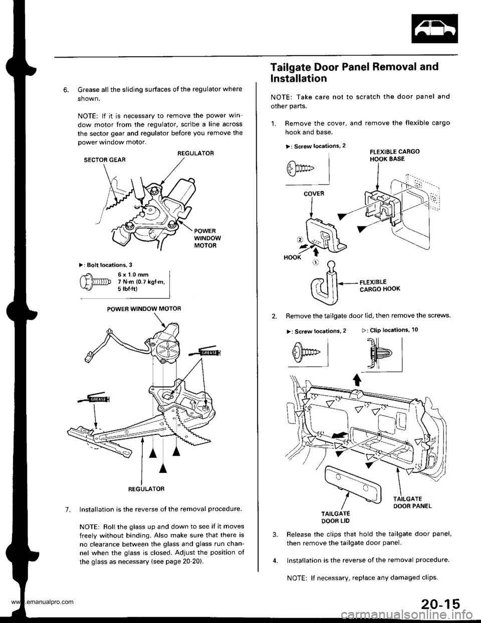
6. Grease all the sliding surfaces of the regulator where
shown.
NOTE: lf it is necessary to remove the power win-
dow motor from the regulator, scribe a line across
the sector gear and regulator before you remove the
power window motor.
REGULATORSECTOR GEAB
POWERwtNDowMOTOR
>: Bolt locations.3
6x1.0mm7 N.m 10.7 kgf.m,5 rbnftl
POWER WINDOW MOTOR
REGULATOR
7. lnstallation is the reverse of the removal procedure.
NOTEr Roll the glass up and down to see if it moves
freely without binding. Also make sure that there is
no clearance between the glass and glass run chan-
nel when the glass is closed. Adjust the position of
the glass as necessary {see page 20 20).
1. Remove the cover,
hook and base.
>: Screw locations.2
Tailgate Door Panel Removal and
lnstallation
NOTE: Take care not to scratch the door panel and
other parts.
and remove the flexible cargo
FLEXIBLE CARGOHOOK BASE
>: CliP locations.
?11 |
HPI,4| |
I
FLEXIBLECARGO HOOK
2. Remove the tailgate door lid, then remove the screws.
>: Screw locations.2
TAILGATEDOOR LIO
Release the clips that hold the tailgate door panel,
then remove the tailgate door panel.
Installation is the reverse of the removal procedure.
NOTE: lf necessary, replace any damaged clips.
3.
@t"
COVER
i
20-15
www.emanualpro.com
Page 998 of 1395
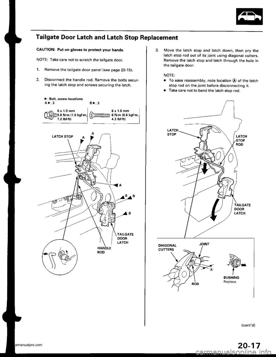
Tailgate Door Latch and Latch Stop Replacement
CAUTION: Put on gloves to protect your hands.
NOTE: Take care notto scratch the tailgate door.
'1. Remove the tailgate door panel (see page 20-15).
2. Disconnect the handle rod. Remove the bolts secur-
ing the latch stop and screws securing the latch.
>: Bolt, screw locationsA>,3 B>,3
6x1.0mm
3. Move the latch stop and latch down, then pry the
latch stop rod out of its joint using diagonal cutters.
Remove the latch stop and latch through the hole in
the tailgate door.
NOTE:
. To ease reassembly, note location @ of the latch
stop rod on the joint before disconnecting it.. Take care not to bend the latch stop rod.
''-t.-Ngta
-\S/r
tBUSHING
(cont'd)
20-17
www.emanualpro.com