seat memory HONDA CR-V 1999 RD1-RD3 / 1.G Workshop Manual
[x] Cancel search | Manufacturer: HONDA, Model Year: 1999, Model line: CR-V, Model: HONDA CR-V 1999 RD1-RD3 / 1.GPages: 1395, PDF Size: 35.62 MB
Page 1310 of 1395
)
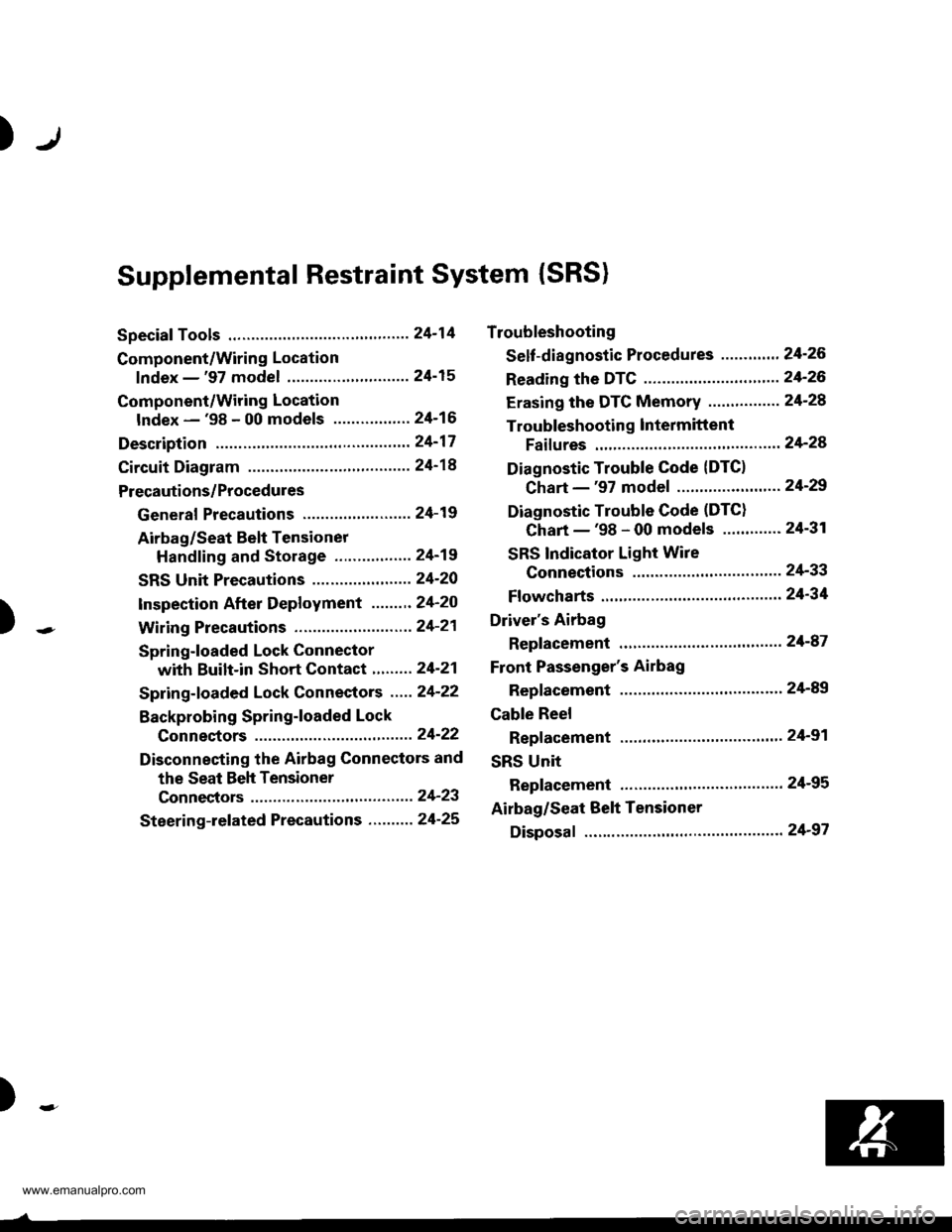
Supplemental Restraint System (SRS)
Special Tools .."....."" 24-14
Component/Wring Location
lndex - '97 model ..........'.." '.....""" 24-15
Component/Wiring Location
lndex - '98 - 00 models ..............." 24-16
Description .'.........."'.24'17
Circuit Diagram .........24'14
Precautions/Procedures
General Precautions ......".."'........... 24-19
Airbag/Seat Belt Tensioner
Handling and Stolage ....''........... 24-19
SRS Unit Precautions ...............'...... 24-20
lnspeciion After Deployment .......'.24'20
)
with Built-in Short Contact '...'....24-21
Spring-loaded Lock Connectors .."' 24-22
BackProbing SPring-loaded Lock
Conneetors ,.......24-22
Disconnecting the Airbag Connectors and
the Seat Beh Tensioner
Connectors ....'....24-23
Steering-lelated Precautions .......... 24-25
Troubleshooting
Self -diagnostic Procedures ............. 24-26
Reading the DTC .................. .....".."' 24'26
Erasing the DTC Memory ................24-28
Troubleshooting lntermittent
Faifures "'...........24'24
Diagnostic Trouble Gode {DTC}
Chart -'97 model ....""....... "......24-29
Diagnostic Trouble Gode (DTCI
Chart -'98 - 00 models ............. 24-31
SRS Indicator Light Wire
Connections ','," 24'33
Ff owcharts ....-........24'34
Driver's Airbag
Repf acement ..'......21'87
Front Passenger's Airbag
Repfacement .....'.',24'AS
Gable Reel
Replacement .......'.24-91
SRS Unit
Replacement .........24-95
Airbag/Seat Belt Tensioner
Disposaf .................24'97
)-e
www.emanualpro.com
Page 1313 of 1395
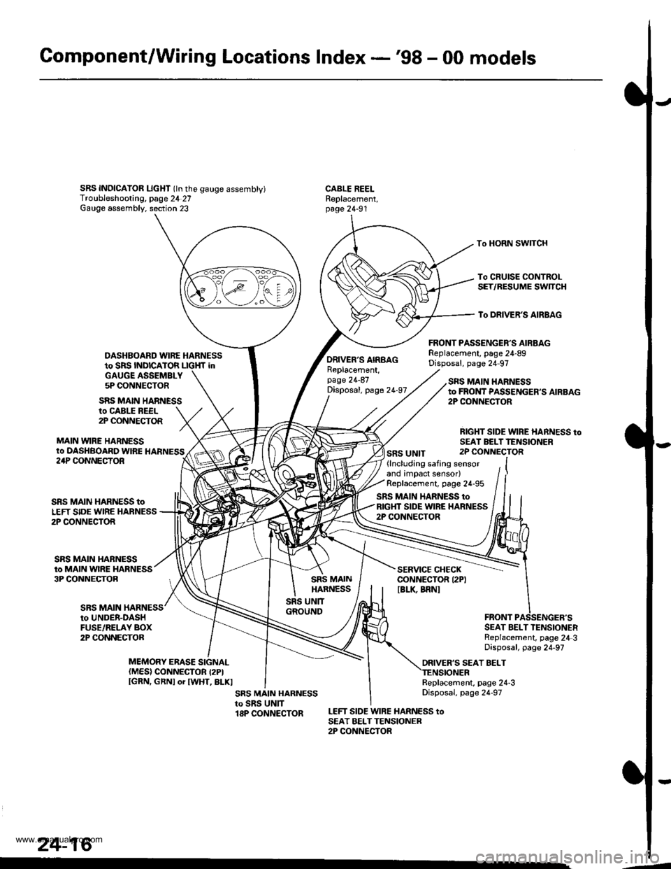
Gomponent/Wiring Locations Index -'98 - 00 models
SRS INDICAIOR LIcHT (ln the gauge assembty)Troubleshooting, page 24 27Gauge assembly. section 23
DASHBOARD WIRE HARNESSto SRS INDICATOR LIGHf inGAUGE ASSEMBLY5P CONNECTOR
FRONT PASSENGER'S AIRBAGReplacement, page 24-89Disposal, page 24 97
CABLE REELReplacement,page 24-91
To HORN SWITCH
To CRUISE CONTROLSET/RESUME SWTCH
To DRIVER'S AIRBAG
ro CABLE REEL2P CONNECTOR
MAIN VYIRE HARNESSto DASHBOARD WIRE HARNESS
SRS MAIN HARNESS
ORIVER'S AIRBAGReplacement,page 24-87Disposal, page 24-97
SRS UNIT
SRS MAIN HARNESSto FROI{T PASSENGER,S AIRBAG2P CONiIECTOR
RIGHT SIDE WIRE HARNESS toSEAI BELTTENSIONER2P CONNECTOR24P CONNECTOR
SRS MAIN
SRS MAIN HARNESS toLEFT SIDE WIRE HARNESS2P CONNECTOR
SRS MAIN HARNESSto MAIN WIRE HARNESS3P CONNECTOB
(lncluding safing sensorand impact sensor)Replacement, page 24-95
SRS MAIN HARNESS toRIGHT SIDE WIRE HARNESS2P CONNECTOR
SERVICE CHECKCONNECTOR I2PIIBLK BRNI
to UNDER-DASHFUSE/RELAY BOX2P CONNECTORSEAT BELT TENSIONERReplacement, page 24 3Disposal, page 24-97
ORIVER'S SEAT BELTMEMORY ERASE SIGNAL(MES) CONNECTOR I2PIIGRN, GRNI or IWHT, BLKIReplacement, page 24-3Disposal, page 24-97
LEFT SIDE WIRE HARNESS toSEAT BELTTENSIONER2P CONNECTOR
24-16
.4
www.emanualpro.com
Page 1314 of 1395
Description
J)
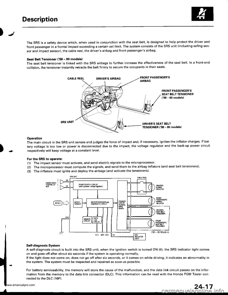
The SRS is a safety device which, when used in conjunction with the seat belt, is designed to help protect the driver and
front passenger in a frontal impact exceeding a certain set limit. The system consists of the SRS unit (including safing sen-
sor and impact sensor), the cable reel, the driver's airbag and front passenger's airbag.
Seat Bolt Tensioner {'98 - 00 models}
The seat belt tensioner is linked with the SRS airbags to further increase the effectiveness of the seat belt. In a front-end
collision, the tensioner instantly retracts the belt firmly to secure the occupants in their seats
FRONT PASSENGER'SAIREAGDRIVER'S AIRBAG
FRONT PASSENGER'SSEAT BELT TENSIONER{'98 - 00 modelsl
)
SRS UNITDRIVER'S SEAT BELTTENSIONER l'98 - 0O modeb)
Operation
The main circuit in the SRS unit senses and judges the force of impact and, if necessary, ignites the intlator charges. lf bat
tery voltage is too low or power is disconnected due to the impact, the voltage regulator and the back-up power circuit
respectively will keep voltage at a constant level.
For the SRS to operate:
(1) The impact sensor must activate, and send electric signals to the microprocessor.
(2) The microprocessor must compute the signals, and send them to the airbag inflators (and seat belt tensioners).
(3) The inflators must ignite and deploy the airbags (and activate the tensioners).
Selt-diagnosis System
A self-diagnosis circuit is built into the SRS uniU when the ignition switch is turned ON (ll), the SRS indicator Iight comes
on and goes off after about six seconds if the system is operating normally.
lf the light does not come on, does not go off after six seconds, or it comes on while driving, it indicates an abnormality in
the system. The system must be inspected and repaired as soon as possible.
For battery serviceability, the memory will store the cause of the malfunction, and the data link circuit passes on the infor
mation from the memory to the data link connector (DLC). This information can be read with the Honda PGM Tester con-
nected to the DLC {16P).
198
---__-l
TENSTO1En II
_-___J- 00 N4ode s)
24-17
www.emanualpro.com
Page 1315 of 1395
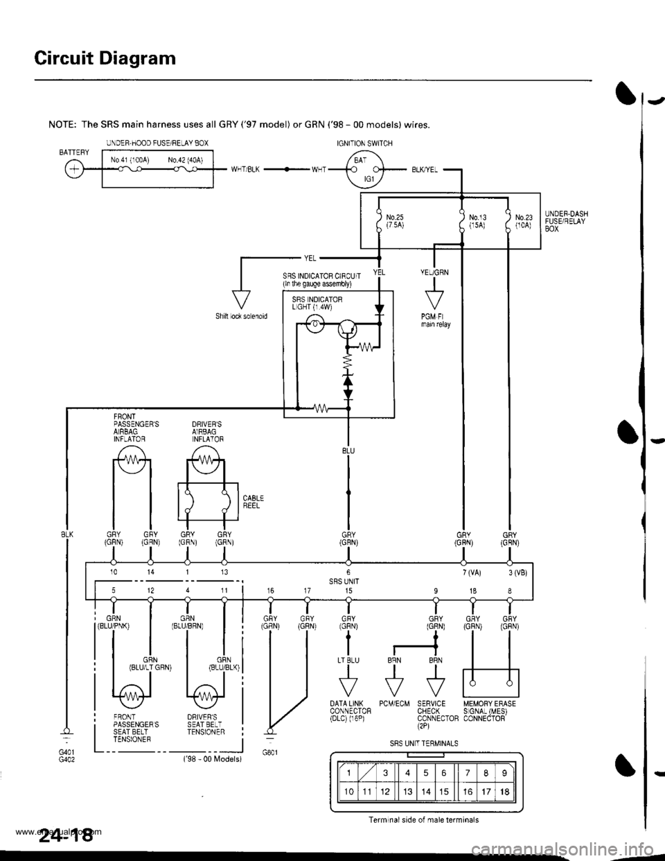
Circuit Diagram
UNDER.DASHFUSE/RELAYBOX
NOTE: The SRS main harness uses all GRY('97 model) or GRN ('98 - 00 models) wires.
WHT/BLK -'- WHT
DRIVEB'SAIRBAGNFLATOR
A
#+
tt tll./ d I
GRY GRY(GRN) (GRN)
FRONTPASSENGER'SALRBAGINFLAlOR
tlGRY GFY(GFN) (GRN)
DRIVER'SSEAT EELTTENSIONER
FRONTPASSENGERSSEAT BELTTENSIONEF
GRN(BLU/PNK)
BLK
G401
24-18
PCM/ECM SERVICE MEMORY ERASECHECK S GNAL (MES)CONNECTOB CONNECTOR(2P)
DATA LINXCONNECTOR(Drc) (r6P)
Models)('98 - 00
IGNITION SWITCHUNDEF,HOOD FUSE/RELAY BOX
YEUGRN
+
PGM FImam relay
SFS INDICATOR CIRCUIT(ln lhe gauge assembly)
Shill loc* so enoid
BLU
GR\
GNY GRY
H
GFY GRYlcFNt (GlN)
??
I r-?LT BLU BRN BRN
tttr?F?F
VVV
SRS NDICATORL GHT {r.4W)
5 12 4 11 | 16 17 15 I 18 I
10 14 113
U
S8S UN T TERMINALS
3567I
101114151718
Terminal side of male terminals
-4
www.emanualpro.com
Page 1339 of 1395
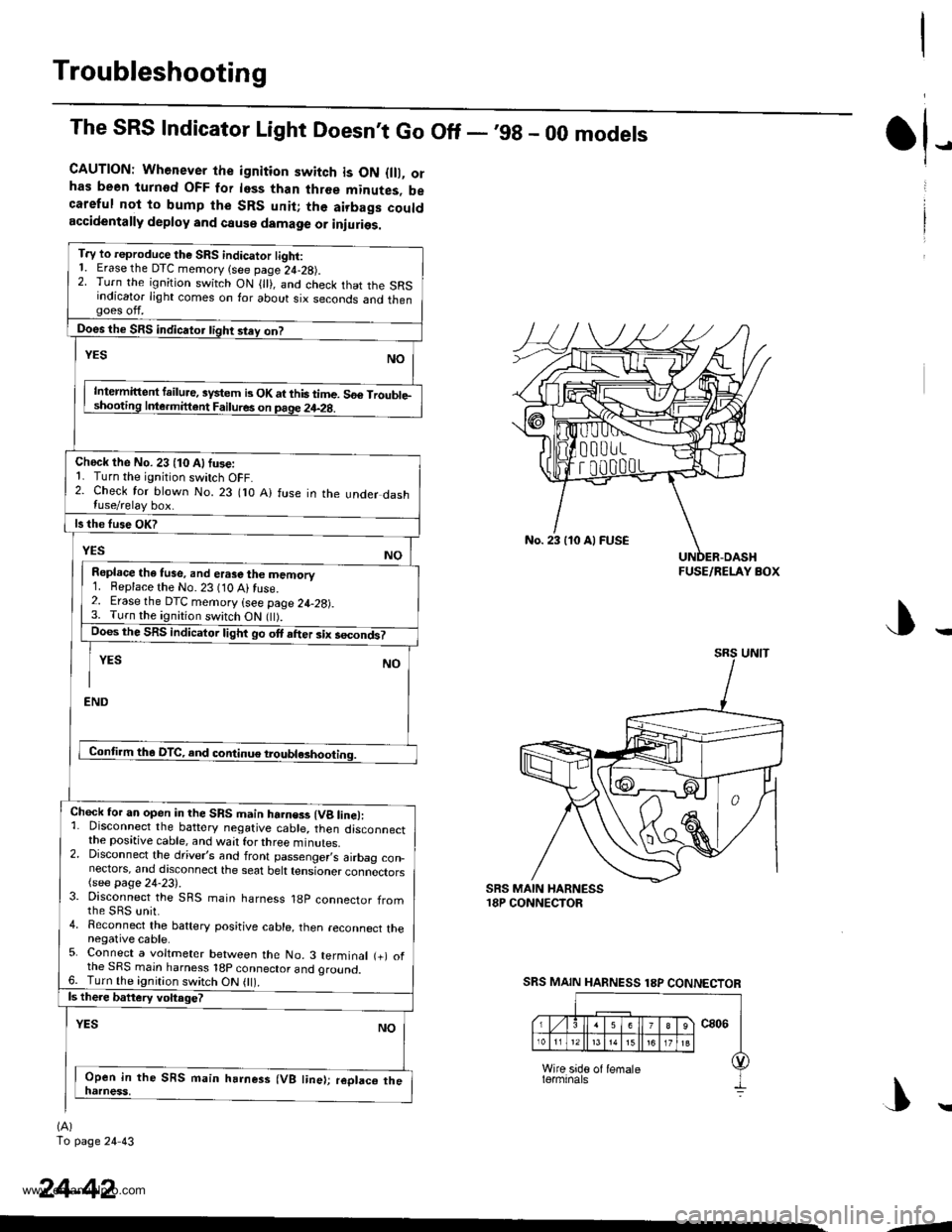
Troubleshooting
The SRS Indicator Light Doesnt Go Off - ,99 - 00 models
CAUTION: Whenever the ignition switch is ON {lll, orhas been turnod OFF for less than three minutes, becareful not to bump the SRS unit; the airbags couldaccidentally deploy and cause damage or iniuries.
T.y to reproduce the SRS indicator tight:1. Erase the DTC memory (see page 24-28).2. Turn the ignition switch ON { }, and check that the SRSindicator light comes on for about six seconds and thengoes off.
Does the SRS indicator tight stey on?
NOYES
Intermittent failure, system b OK at this time. 56€ Trouble-shooting Inle.mittent Failures on page 24-2g.
Check the No. 23 (10 Alfuse:1. Turn the ignition switch OFF.2. Check for blown No. 23 flO A) fuse in the under dashluse/relay box.
ls the fuse OK?
YESNO
Repl.ce the tuse, and erase the memory1. Beplace the No. 23 (10 Ai fuse.2. Erase the DTC memory (see page 24-28).3. Turn the ignition switch ON flt).Does the SRS indicator light go ott after six secondt
YES NO
I
END
Conti.m tha DTC, and continue troubl*hooting.
Chock for an open in the SRS main harness (Vg line):1. Disconnect the battery negative cable, then disconnectthe positive cable, and wait for three minutes.2. Disconnect the driver,s and front passenger,s airbag con_nectors, and discoonect the seat belt tensioner connectors(see page 24-23).3. Disconnect the SRS main harness 18p connector fromthe sRs unit.4. Reconnect the baftery positive cable, then reconnect thenegative cable.5. Connect a voltmeter between the No. 3 terminal (+) ofthe SRS main harness 18p connector and oround.6. Turn the ignition switch ON 0l).ls there battery voltage?
YESNO
Open in the SRS main harness (VB line); replaco thenatness,
(A)
To page 24 43
tl-
24-42
No. 23 110 Al FUSE
FUSE/RELAY BOX
SRS MAIN HARNESS 18P CONNECTOR
|\
-1
www.emanualpro.com
Page 1348 of 1395
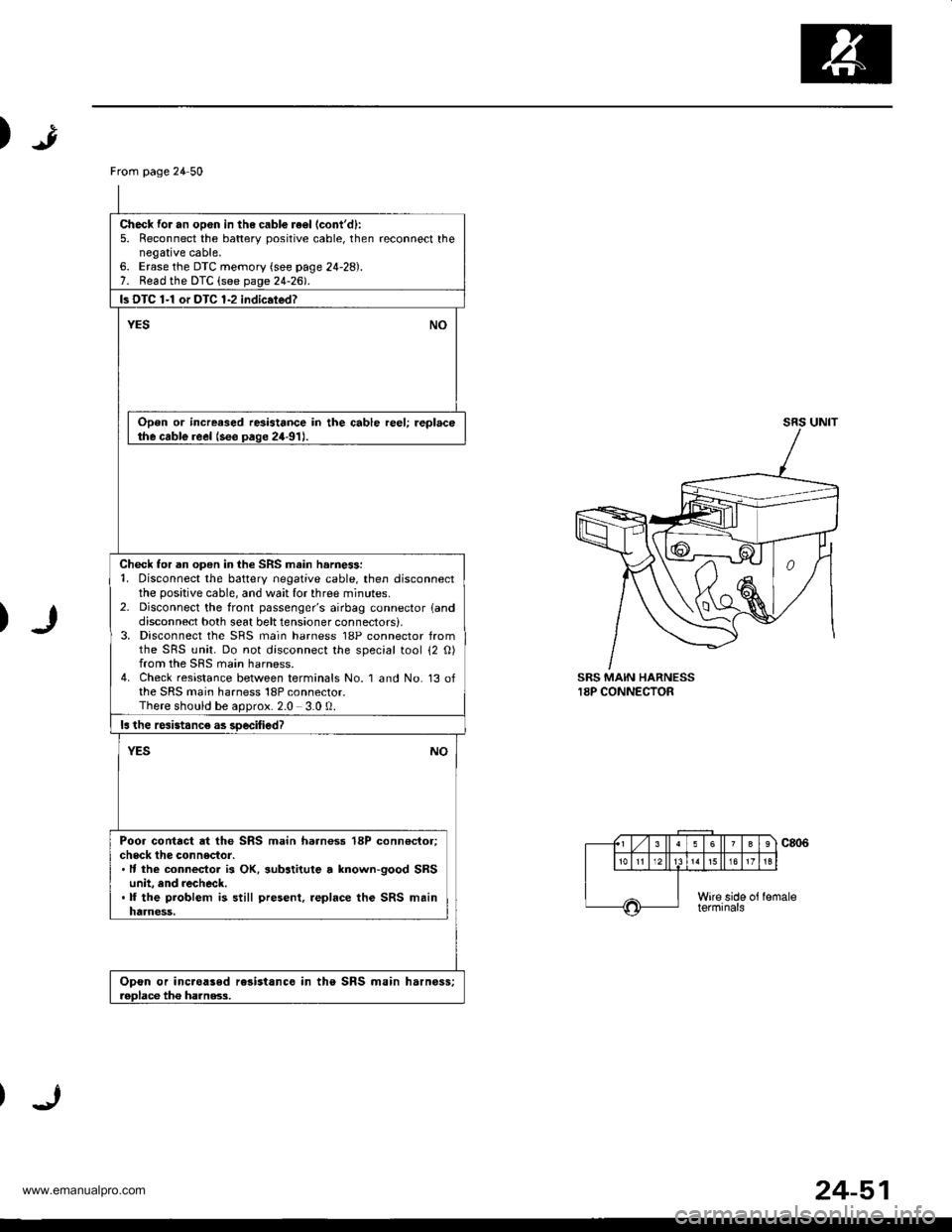
)
)
SRS MAIN HARNESS18P CONNECTOR
From page 24 50
Check for an opon in the cabl€ re€l (cont'd):
5. Reconnect the batterv positive cable, then reconnect thenegative cable,6. Erase the DTC memory (see page 24-28).7. Read the DTC (see page 24-2d.
ls DTC 1-1 or DTC 1-2 indic.ted?
YESNO
Open or increased resistance in the cable reel; replacethe cable reel (see paqe 24-91J.
Check for an open in the SRS main harne$:1. Disconnect the battery negative cable, then disconnectthe positive cable, and wait lor three minutes.2- Disconnect the front passenger's airbag connector landdisconnect both seat belt tensioner connectors),3, Disconnect the SRS main harness 18P connector fromthe SRS unit. Do not disconnect the special tool 12 O)from the SRS main harness.4. Check resistance between terminals No. 1 and No. 13 ofthe SRS main harness 18P connector.There should be aoorox.2.0 3.0 0.
ls the rcsistanc€ as soecified?
NOYES
Poor contact at the SRS main harnoss 18P conn€ctor;check the connector.. It the connecior is OK, substitute a lnown-good SRSunit, and recheck..lf the problem is still present, .eplace the SRS mainharness,
Opon or inc.oased rc3istance in the SRS main harnoss;roDlace tho ha]nss.3.
24-51
www.emanualpro.com
Page 1350 of 1395
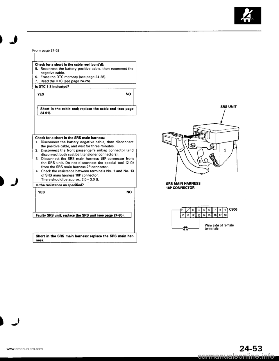
From page 24-52
Chock for a shon in th6 cablo recl {cont'dl:5. Reconnect the battery oositive cable, then reconnect thanegative cable.6. Ersse the DTC memory (see page 24-28).7. Read the DTC (see page 24-26l'.
ls DTC 'l-3 indic{tod?
NOYES
Short in the csble reel; replace tha cabls rcol lsao paga
24-911.
Chock for a short in th€ SRS main ha.nors:1. Disconnect the battery negative cable, th€n disconnectthe Dositive cable, and wait for three minutes.2. Disconn€ct tho lront passengor's airbag connector (and
disconnect both seat belt tensioner connectors).3. Disconnect the SRS main harness 18P connector fromthe SRS {rnit. Do not disconnect the special tool (2 0)from the SRS main harness 2P connector.4. Check the resistance between terminals No. 1 and No. 13of SRS main harness 18P connector.There should be aDorox. 2.0 - 3.0 0.
b th€ rsciitlnce a3 sDecifi6d?
NOYES
Faulty SRS unit; rspl.c. th6 SRS unit l.co p.sc 2a-95,,
Shori in the SRS m.in h.rn.e!; ropbce the SRS main htr-ne33.
SRS UNIT
)SRS MAIN HABNESS18P CONNECTOR
c806
)
(., Lzl 3 ll63
1518
Wire side ottormrnats
24-53
www.emanualpro.com
Page 1352 of 1395
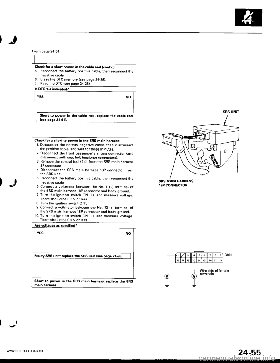
Ftom page24-54
Check for 6 short power in the cable r6el {cont'd):5. Reconnect the battery positive cable, then reconnect thenegative cable.6. Erase the DTC memory (see page 24-28).7. Read the DTC (see page 24-261.
b DTC 1-4 indicarodz
YESNO
Short to power in lhe cablo roel; replace th€ cabl€ ieel{see pago 24-91).
Check tor a short to power in th. SRS main harn$s:1. Disconnect the battery negative cable, then disconnectthe positive cable, and wait for three minutes.2. Disconnect the front passenger's airbag connector {anddisconnect both seat belt tensioner connectors).3. Rernove the special tool (2 O) from the SRS main harness2P connector.4. Disconnect the SRS main harness 18P connector fromthe SRS unit.5. Beconnect the batterv positive cable, then reconnect thenegative cable.6. Connect a voltmeter between the No. 1 {+) terminal olthe SRS main harness 18P connector and body ground.7. Turn the ignition switch ON (ll), and measure voltage.There should be 0.5 V or less.8. Turn the ignition switch OFF.9. Connect a voitmeter between the No. 13 {+i terminal ofthe SRS main harness 18P connector and body ground.10.Turn the ignition switch ON lll), and measure voltage.There should be 0.5 V or less.
Are voltages as specified?
YESNO
Faulty SRS unit; replaco th€ SRS unit lsoo pas6 24-95).
Short to power in th€ SRS main hamoss; roplece the SRSmain haanass.
SRS MAIN HARNESS18P CONNECTOR
24-55
www.emanualpro.com
Page 1363 of 1395
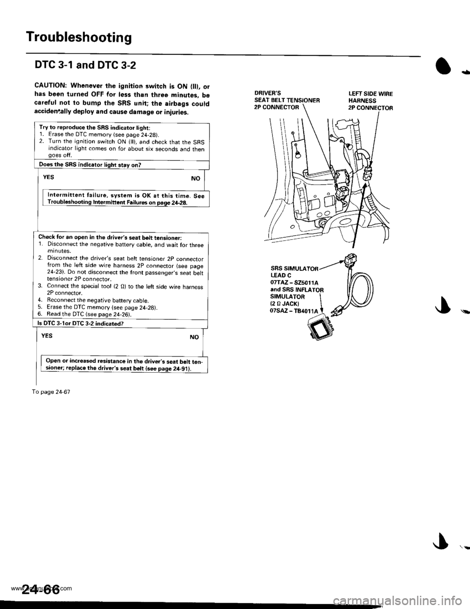
Troubleshooting
DTC 3-1 and DTC 3-2
CAUTION: Whenever the ignition switch is ON flll, orhas been turned OFF for less than three minutes, b€careful not to bump th€ SRS unit; the airbags couldaccidenlally deploy and cause damage or iniuries.
DRIVER'SSEAT BELT TENSIONERLEFT SIOE WIREHARNESS2P CONNECTOR2P CONNECTOR
-
\
SRS SIMULALEAD C07TAZ - SZ501rAand SRS INFLATORSTMULAToR It2 0JACKI IoTsaz - TB4ot lA t
24-66
Try to reproduce the SRS indicatoi light:1. Erase the DTC memory (see page 24-29).2. Turn the ignition switch ON 1 ), and check that the SRSindicator light comes on for about six seconds and thengoes off.
Does the SRS indicaior lighr stay on?
YESNO
Intermittent failure, system is OK at this time. SeeTroubleshooting lfiermittent Failu.6s on page 24-28.
Check tor an open in the driver's seat b6lt tensioner:1. Disconnect the negative battery cable, and wait lor threeminutes.2. Disconnect the drave/s seat belt tensioner 2p connectorfrom the left side wire harness 2P connector (see page24-23). Do not disconnect the lront passenger,s seat belttensioner 2P connector.3. Connect the special tool {2 O) to the left side wire harness2P connector,4. Reconnect the negative baftery cable5. Erase the DTC memory {see page 24,28).6. Read the DTC (see page 24-26).
ls OTC 3-1or DTC 3-2 indicatedT
YESNO
Open or increased resistance in the d.iver's seat belt ten-sioner; replace the driver's seat belt {see page 2il-91).
To page 24 67
www.emanualpro.com
Page 1364 of 1395
)
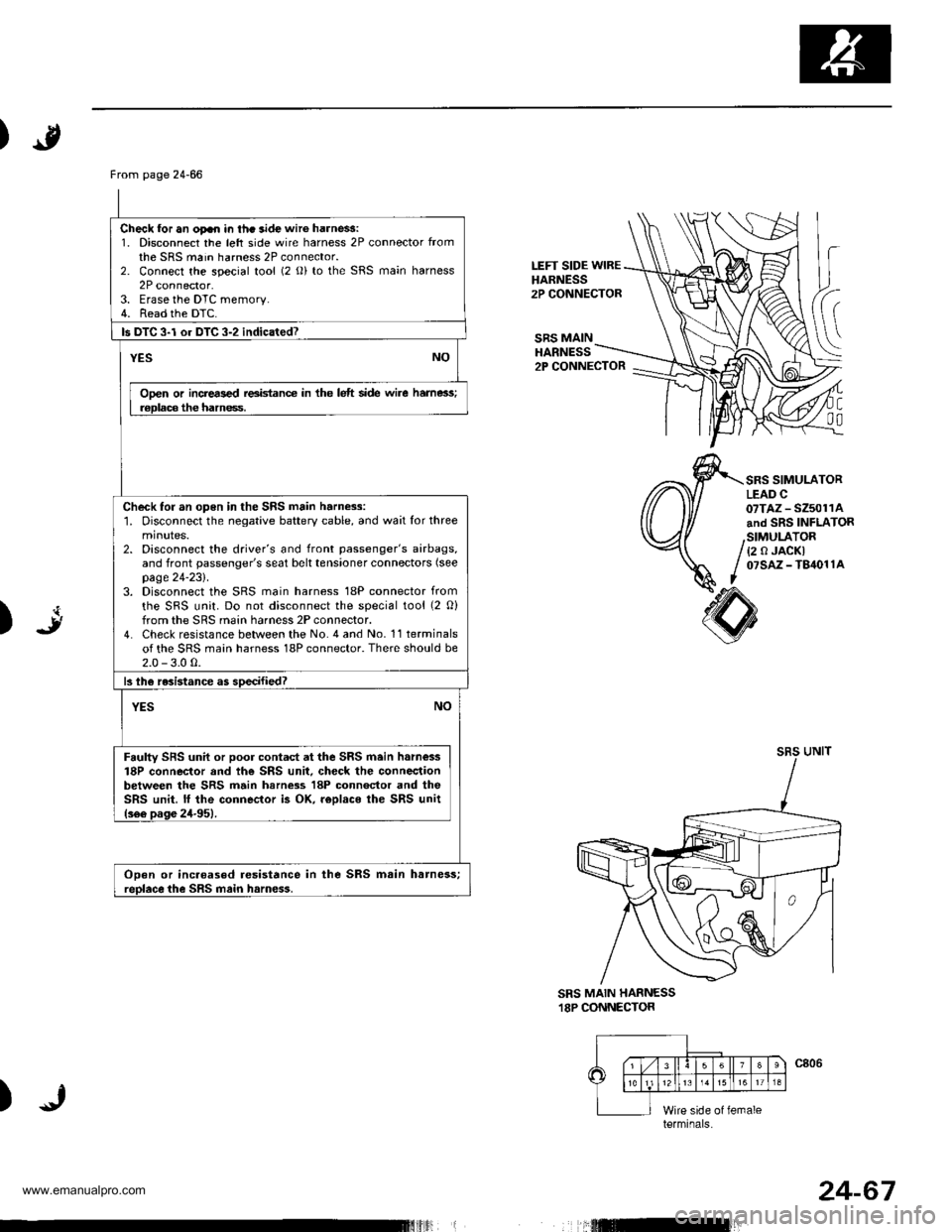
LEFT SIDE WIREHARNESS2P CONNECTOR
SRS MAINHARNESS2P CONNECTOR
C
00
SRS SIMULATORLEAD C07TAZ - SZ5011Aand SRS INFLATOR
{2 0 JACKI07sAz - T84011A
art)
sRsUNIT
SRS MAIN HARNESS.I8P CONNECTOR
)
From page 24-66
Check for an oFn in thc aide wir6 harne$:1. Disconnect the left side wire harness 2P connector fromthe SRS main harness 2P connector.2. Connect the special tool (2 o) to the SRS main harness2P connector.3. Erase the DTC memory.4. Read the DTC.
ls DTC 3-l or DTC 3-2 indicated?
YESNO
Ooen or incrers€d reeidance in the lelt side wire hame3s;r€Dlaca the hamess.
Check for an open in the SRS main harness:1. Disconnect the negative battery cable, and wait for threeminutes.2. Disconnect the driver's and front passenger's airbags,and front passenger's seat belt tensioner connectors (see
page 24-231.3. Disconnect the SRS main harness 18P connector from
the SRS unit. Do not disconnect the special tool (2 O)from the SRS main harness 2P connector.4. Check resistance between the No. 4 and No. 11 terminalsof the SRS main harness 18P connector. There should be2.0 - 3.0 0.
13lhe resistance as soecified?
NOYES
Faulty SFS unil or poor contad at the SRS main h.m€ss18P connector and th€ SRS unit. check the connectionbetween the SRS main harn$s 18P connector and theSRS unit. lf the connector i3 OK. r€Dlaco ihe SRS unit(s66 pas6 24-951.
ODen or incaoased resistance in the SRS msin harness;reolace the SRS main harn€ss.
terminals
24-67
www.emanualpro.com