Air mix HONDA CR-V 1999 RD1-RD3 / 1.G User Guide
[x] Cancel search | Manufacturer: HONDA, Model Year: 1999, Model line: CR-V, Model: HONDA CR-V 1999 RD1-RD3 / 1.GPages: 1395, PDF Size: 35.62 MB
Page 1103 of 1395
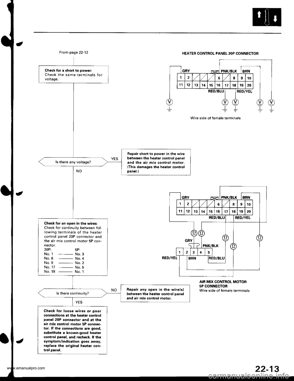
Ftom page 22.12HEATER CONTROL PANEL 2OP CONNECTOR
Wire side ol female terminals
Check tor a short to poweriCheck the same terminals forvoltage.
Repair shon lo power in the wi.ebetween the heater control paneland the air mix control motor,(This damages the heater controlDanel.l
Check tor an open in the wires:Check for continuity between fol-lowing terminals of the heatercontrol panel 20P connector andthe air mix control motor 5P con-nector,zOPi 5P:No. 1 - No.3No.6 _ No. 4No.g _ No.2No. 17 _ No.5No. 18 _ No. 1
Repair any open in the wire{s)betweon the heater control panel
and air mix control motor.
Check toa loos€ wir63 or poorconnections rl the heater controlpanel 20P connector and st theair mix control motor 5P connsc-tor. lJ the connections aro good,substitute a known-good hoatercontrol panel, and rechock. I thesymptom/indication goes away,..pl.ce the original heater con-trol panel.
REO/8LURED/YEL
RED/YEL
AIR MIX CONTROL MOTOR5P CONNECTORWire side of female terminals
www.emanualpro.com
Page 1130 of 1395
Troubleshooting
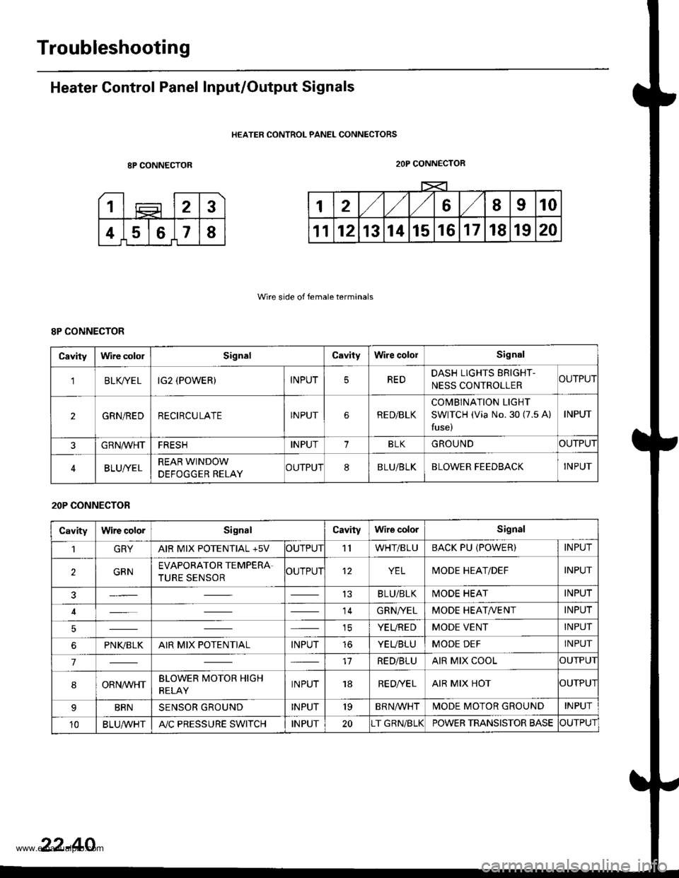
Heater Control Panel Input/Output Signals
HEATER CONTROL PANEL CONNECTORS
8P CONNECTOR
Wire side of female terminals
2OP CONNECTOR
8P CONNECTOR
Cavitylrvire cololSignalCavityWire cololSignal
'lBLK/TE LIG2 (POWER)INPUTREDDASH LIGHTS ERIGHT-
NESS CONTROLLERCUTPUT
2GRN/REDRECIRCULATEINPUTRE D/BLK
COMBINATION LIGHT
SWITCH (Via No. 30 (7.5 A)
fuse)
INPUT
GRN/VVHTFRESHINPUT1BLKGROUNDOUTPUT
BLUI/ELREAR WINDOW
DEFOGGER RELAYCUTPUT8BLU/BLKBLOWER FEEDBACKINPUT
20P CONNECTOR
CavityWire colorSignalCavityWire colorSignal
1GRYAIR MIX POTENTIAL +5VOUTPUT'llWHT/BLUBACK PU (POWER)INPUT
2GRNEVAPORATOR TEMPERA.
TURE SENSOROUTPUT12YELMODE HEAT/DEFINPUT
13BLU/BLKMODE HEATINPUT
14GRN/YELMODE HEAT/VENTINPUT
ICYEUREDMODE VENTINPUT
6PNI(BLKAIR MIX POTENTIALINPUTtoYEUBLUMODE DEFINPUT
717RED/BLUAIR MIX COOLOUTPUI
8ORNrur'HTBLOWER MOTOR HIGH
RELAYINPUT18RE D/VE LAIR MIX HOTOUTPUI
BRNSENSOR GROUNDINPUT'19BRNA/VHTIVIODE MOTOR GROUNDINPUT
10BLU,ryVHTA"/C PRESSURE SWITCHINPUT20T GRN/BLKPOWER TRANSISTOR BASECUTPUT
22-40
www.emanualpro.com
Page 1133 of 1395
Air Mix Gontrol Motor
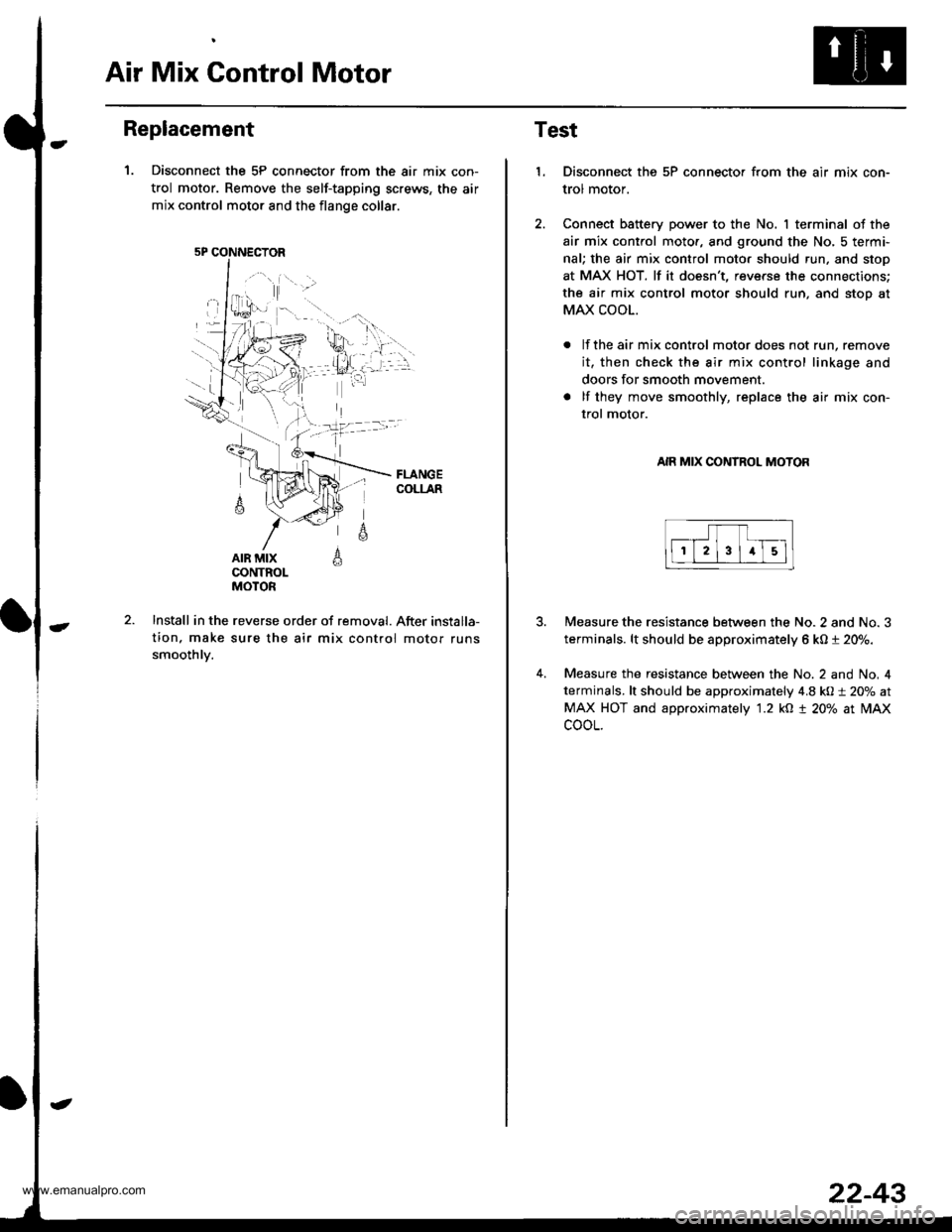
Replacement
1. Disconnect the 5P connector from the air mix con-
trol motor. Remove the self-tapping screws, the air
mix control motor and the flange collar.
AIR MIXCONTROLMOTOR
A
6
Install in the reverse order of removal. After installa-
tion. make sure the air mix control motor runs
smoothlv.
5P CONNECTOR
22-43
Test
1.Disconnect the 5P connector from the air mix con-
trol motor.
Connect battery power to the No. I terminal of the
air mix control moto., and ground the No, 5 termi-
nal; the air mix control moto. should run, and stop
at MAX HOT. lf it doesn't, reverse the connections;
the air mix control motor should run, and stoo at
MAX COOL.
lf the air mix control motor does not run, remove
it, then check the air mix control linkage and
doors for smooth movement.
lf they move smoothly, replace the air mix con-
trol motor.
AIR MIX CONTROL MOTOR
4.
Measure the resistance between the No. 2 and No. 3
terminals. lt should be approximately 6 kO t 20%.
Measure the resistance between the No. 2 and No, 4
terminals, lt should be approximately 4.8 kO:t 20% at
MAX HOT and approximately '1.2 kO t 20% at lilAx
cooL.
www.emanualpro.com
Page 1141 of 1395
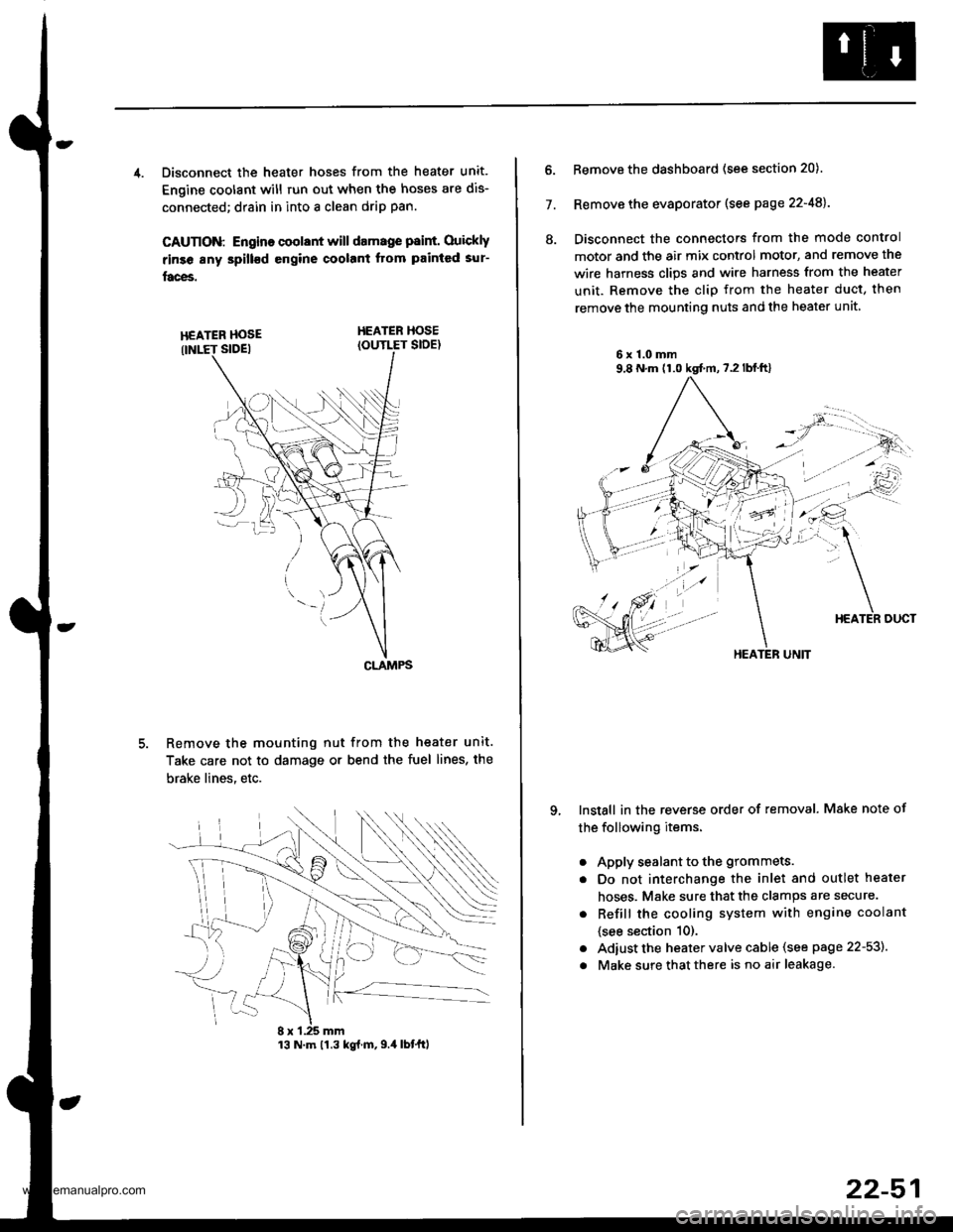
4. Disconnect the heater hoses from the heater unit.
Engine coolant will run out when the hoses are dis-
connected; drain in into a clean drip pan.
CAUTION: Engino coolant will damage p8int. Ouickly
rinse any spill€d engine coolant Itom painted sur-
faces.
HEATER HOSEIOUTLET SIDE)
Remove the mounting nut from the heater unit.
Take care not to damage or bend the fuel lines, the
brake lines. etc.
CLAMPS
13 N.m 11.3 kg{.m,9.4 lbtftl
22-51
7.
ll.
Remove the dashboard (see section 20).
Remove the evaporator (see page 22-48).
Disconnect the connectors from the mode control
motor and the air mix control motor, and remove the
wire harness clips and wire harness from the heater
unit. Remove the clip from the heater duct, then
remove the mounting nuts and the heater unit
6x1.0mm9,8 N.m (1.0 kgt m,7.2lblft)
qInstall in the reverse order of removal. Make note of
the following items.
a
a
a
a
Apply sealant to the grommets.
Do not interchange the inlet and outlet heater
hoses. Make sure that the clamps are secure.
Refill the cooling system with engine coolant
{see section 10).
Adiust the heater valve cable (see page 22-53).
Make sure that there is no air leakage.
HEATER UNIT
www.emanualpro.com
Page 1143 of 1395
Temperature Control
Adjustment
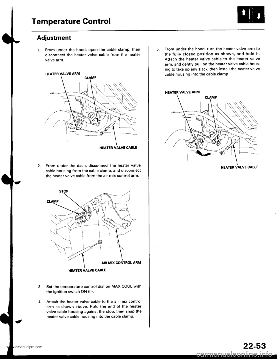
l. From under the hood, open the cable clamp, then
disconnect the heater valve cable from the heater
vatve arm.
From under the dash, disconnect the heater valve
cable housing from the cable clamp. and disconnect
the heater valve cable from the air mix contlol arm
Set the temperature control dial on MAX COOL with
the ignition switch ON (ll).
Attach the heater valve cable to the air mix control
arm as shown above. Hold the end of the heater
valve cable housing against the stop, then snap the
heater valve cable housing into the cable clamp.
HEATER VALVE ARM
HEATER VALVE CABLE
5. From under the hood. turn the heater valve arm to
the fullv closed position as shown, and hold it.
Attach the heater valve cable to the heater valve
arm, and gently pull on the heater valve cable hous-
ing to take up any slack, then install the heate. valve
cable housing into the cable clamp.
HEATER VALVE ARM
HEATER VALVE CABLE
22-53
www.emanualpro.com
Page 1144 of 1395
A/C Service Tips and Precautions
The air conditioner system uses HFC-'134a (R-134a) refrigerant and polyalkyleneglycol {PAG) refrigerant oil*, which are not
compatible with CFC-12 (R-12) refrigerant and mineral oil. Do not use R-12 refrigerant or mineral oil in this system, and do
not attempt to use R-12 servicing equipmenu damage to the air conditioner system or your servicing equipment will
resutr.
*KEIHIN SP-10:
. P/N 38897 - Pl3 - A01AH: 120 m{ (4 fl.oz, il.2 lmp.oz)
. P/N 38899 - Pl3 - A01: 40 mf 11113tl.oz,1.4 lmp.oz)
Use only service equipment that is U.L.-listed and is certified to meet the requirements of SAE J2210 to remove R-134a
from the air conditioner system,
CAUTION: Exposure to air conditioner refrigerant and lubricant vapor or misl can irritats eyes, nose and throat. Avoid
breathing the air conditioner refrigerant and lubricant vapor or mist,
lf accidental system discharge occurs, ventilate work area before resuming service.
R 134a service equipment or vehicle air conditioner systems should not be pressure tested or leak tested with compressed
air.
E@ Some mixtures of air and R-13,1a have been shown to be combustible at elevat€d pressures and can result
in fire or explosion causing iniury or property damage. Never use complessed air to pressure test R-l3,[a service equip-
ment or vehicle air conditioner systems.
Additional health and safety information may be obtained from the refrigerant and lubricant manufacturers.
1. Always disconnect the negative cable from the battery whenever replacing air conditioning parts.
2. Keep moisture and dust out of the system. When disconnecting any lines, plug or cap the fittings immediately; don't
remove the caps or plugs until just before you reconnect each line.
3. Before connecting any hose or line. apply a few drops of refrigerant oilto the O-ring,
4. When tightening or loosening a fitting, use a second wrench to support the matching fitting.
5. When discharging the system, use a R l34a refrigerant recovery/recycling/charging station; don't release refrigerant
into the atmosphere.
6. Add refrigerant oil after replacing the following parts.
Note these items when handling refrigerant oil:
o To avoid contamination, do not return the oil to the container once dispensed, and never mix it with other refriger-
ant oils.
. lmmediately after using the oil, replace the cap on the container, and seal it to avoid moisture absorption.
. Do not spill the refrigerant oil on the vehicle; it may damage the painu if the refrigerant oil contacts the paint, wash
it off immediately.
Condenser . 25 ml (5/6 tl.oz, 0.9 lmp.oz)
Evaporator.,................................40 m/ 11 113ll.oz,l.4 lmp.ozl
Line or hose ........... 10 ml (1/3 fl.oz, 0.4 lmp.oz)
Receiver/Dryer....... 10 ml (1/3 fl.oz, 0.4 lmp.oz)
Leakage repair............................ 25 m/ (5/6 ll.oz, 0.9 lmp.oz)
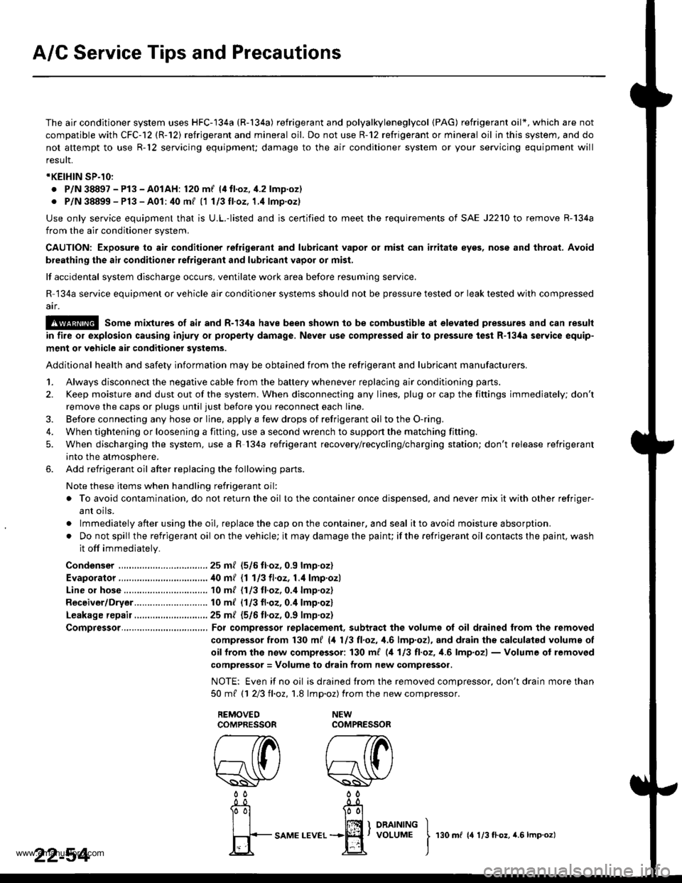
Compressor.......,..., For compressor replacement, subtract the volumg ol oil drained from the removed
compressor from 130 m{ (4 113 tl.oz, 1,6lmp.ozl, and drain the calculatsd volume of
oif from the now comprossor: 130 ml (,1 113 tl,oz, 1.6lmp'ozl - Volume of removed
compressor = Volume to drain from new compressor.
NOTE: Even if no oil is drained trom the removed compressor, don't drain more than
50mt 11 213ll,oz,1.8 lmp.oz) from the newcompressor.
22-54I
rso m r rr:0.o., r.s r-o.o.t
www.emanualpro.com
Page 1146 of 1395
A/G System Service
Performance Test
The performance test will helD determine if the air con-
ditioner system is operating within specifications.
Use only service equipment that is U.L.-listed and is cer-
tified to meet the requirements of SAE J2210 to remove
HFC-134a (R-134a) from the air conditioner svstem.
CAUTION: Exposure to air condiiioner r€trigerant and
lubricant vapor or mist can irritate €yes, nose and
throat. Avoid bre8thing the air conditioner retrige.ant
and lubricant vapor or mist,
lf accidental system discharge occurs. ventilate work
area before resuming service.
R-134a service equipment o. vehicle air conditioner sys-
tems should not be pressure tested or leak tested with
comDressed air.
@ some mixtur€s ol air and R-134a have becn
shown to be combuslible at olsvated pressures and can
result in lire or explosion causing iniury or property
damage. Never use compressed air to prgssure test R-
13i[a service equipment or vehicle air conditioner sys.
tems.
Additional health and safety information may be obtained
from the refrigerant and lubricant manufacturers.
Recovory/Recycling/charging station
LOW.PRESSURESIDE
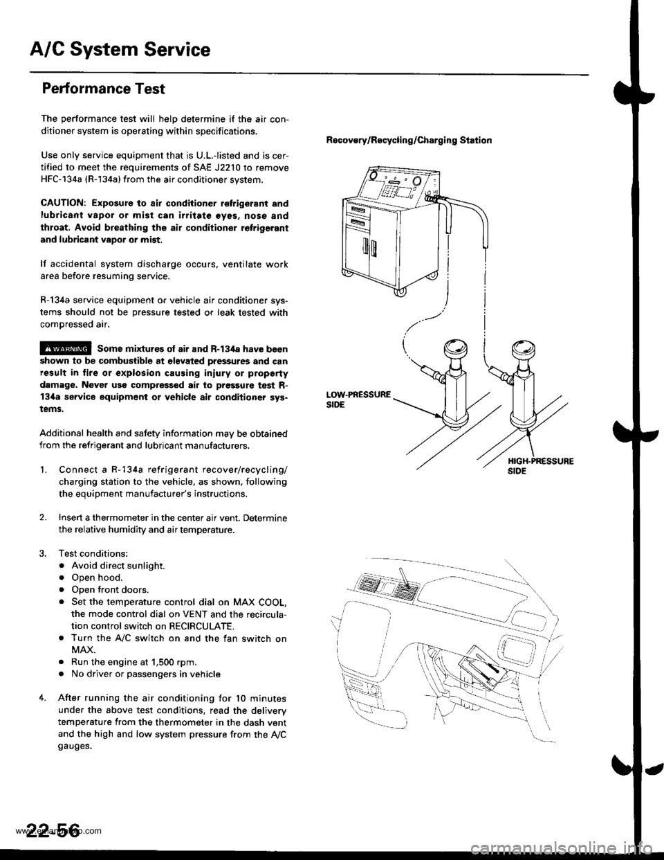
1.Connect a R-134a refrigerant recover/recycling/
charging station to the vehicle, as shown. following
the equipment manufacturer's instructions,
Insen a thermometer in the center air vent. Determine
the relative humidity and air temperature.
Test conditions:
. Avoid direct sunlight.
o Open hood.
. open front doors.
. Set the temperature control dial on MAX COOL,
the mode control dial on VENT and the reci.cula-
tion control switch on RECIRCULATE.
. Turn the A,/C switch on and the fan switch on
MAX.
. Run the engine at 1,500 rpm.
. No driver or passengers in vehicle
After running the air conditioning for 10 minutes
under the above test conditions, read the deliverv
temperature from the thermometer in the dash vent
and the high and low system pressure from the Ay'Cgauges.
2.
22-56
www.emanualpro.com
Page 1149 of 1395
Recovery
Use only service equipment that is U.L.-listed and is cer-
tified to meet the requirements of SAE J2210 to remove
HFC-134a (R-134a) from the air conditioner system.
CAUTION: Exposure to air conditioner refrigerant and
lubricant vapor or mist can irritate eyes, nose and
throat. Avoid brqathing the air conditioner retrigerant
and lubricant vapor or mist.
lf accidental system discharge occurs, ventilate work area
before resuming service.
R-134a service equipment or vehicle air conditioner sys-
tems should not be pressure tested or leak tested with
compressed arr.
@@ some mixtures of air and R-134a have been
shown to be combustible at elevated plessures and can
result in fire or explosion causing iniury or property dam-
age. Never use compressed air to pressure tect R-134a
service equipment or vehicle air conditioner systems.
Additional health and safety intormation may be obtained
from the refrigerant and lubricant manufacturers.
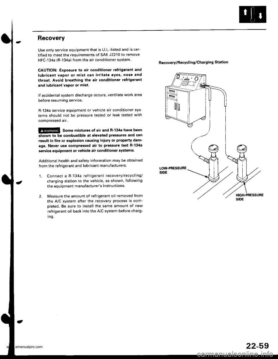
'1. Connect a R-134a refrigerant recove rylrecycling/
charging station to the vehicle, as shown, following
the equipment manufacturer's instructions
2. Measure the amount of refrigerant oil removed trom
the A,/C system after the recovery process is com-
oleted. Be sure to install the same amount of new
refrigerant oil back into the AVC system before charg-
inq.
Recovery/Recycling/Charging Station
22-59
www.emanualpro.com
Page 1150 of 1395
A/C System Service
Evacuation
Use only service equipment that is U.L.-listed and is cer-tified to meet the requirements of SAE J2210 to removeHFC-134a {R-134a)from the air conditioner system.
CAUTION: Exposure to air conditioner refrigerant andlubricant vapor or mist can irrhate eyes, noso and throat.Avoid breathing the air condhioner retrigerant and lubri-cant vapor or mist.
lf accidental system discharge occu.s. ventilate workarea before resuming service.
R 134a service equipment or vehicle air conditioner sys-tems should not be pressure tested or leak tested withcompressed arr.
!@ some mixtures of air and R-134a hsvo beenshown to be combustible at elevated pressures and canresult in tire or explosion causing iniury ot property
damage. Never use compressed air to pressure test R-134a service equipment or vehicle air conditioner svs-tems.
Additional health and safety information may be obtainedfrom the refrigerant and lubricant manufacturers.
1, When an A,/C System has been opened to the atmo-
sphere, such as during installation or repair, it must
be evacuated using a R-l34a refrigerant recovery/
recycling/charging station. {lf the system has beenopen for several days, the receiver/dryer should bereplaced, and the system should be evacuated forseveral hours.)
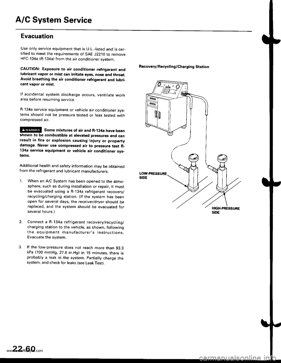
Connect a R-134a refrigerant recovery/recyclin g/
charging station to the vehicle, as shown, following
the equipment manufacturer's instructions.
Evacuate the system,
lf the low-pressure does not reach more than 93.3kPa (700 mmHg,27.6 in.Hg) in 15 minutes, there isprobably a leak in the system. partially charge thesystem, and check for leaks (see Leak Test).
Recovery/Recycling/Charging Station
22-60
www.emanualpro.com
Page 1151 of 1395
Charging
Use only service equipment that is U.L.-listed and is cer-
tified to meet the requirements of SAE J2210 to remove
HFC-134a (R-134a) from the air conditioner system.
CAUTION: Exposure to air conditioner refrigerant and
lubricant vapor or mist can irritate eyes, nose and
throat. Avoid breathing th€ air conditioner refrigerant
and lubricant vapor or mist.
lf accidental system discharge occurs, ventilate work
area before resuming service. Additional health and
safety information may be obtained from the relrigerant
and lubricant manufacturers.
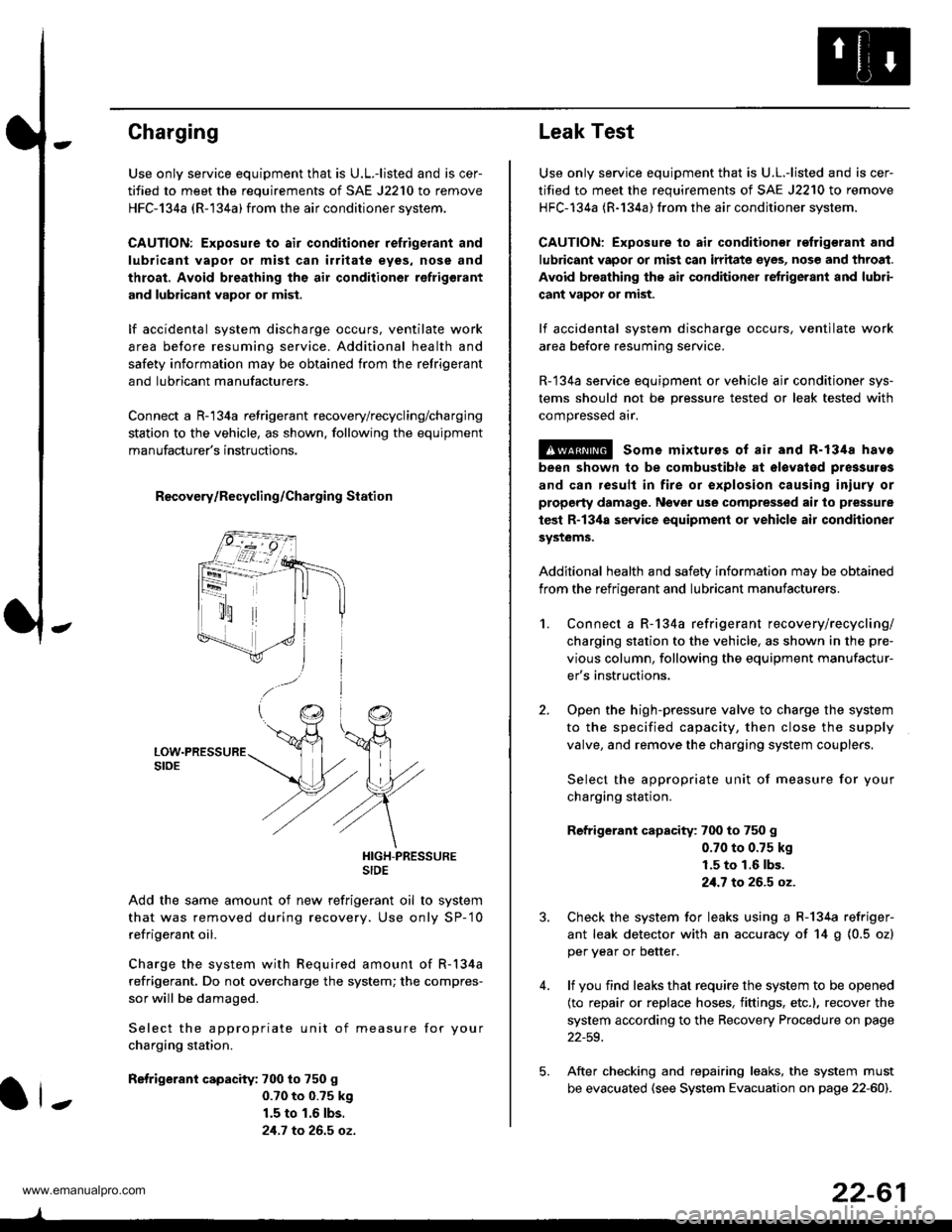
Connect a R-'134a refrigerant recovery/recycling/charging
station to the vehicle, as shown. following the equipment
manufacturer's instructions.
R€covery/Recycling/Charging Station
HIGH-PRESSURESIDE
Add the same amount of new refrigerant oil to system
that was removed during recovery. Use only SP-'10
refrigerant oil.
Charge the system with Required amount of R-134a
refrigerant. Do not overcharge the system; the compres-
sor will be damaged.
Select the appropriate unit of measure for your
charging station.
Refrigerant capacity: 700 to 750 g
0.70 to 0.?5 k9
1.5 to 1.6 lbs.
21.7 to 26.5 oz.
ll-
22-61
Leak Test
Use only service equipment that is U.L.-listed and is cer-
tified to meet the requirements of SAE J2210 to remove
HFC-134a (R-134a) from the air conditioner system.
CAUTION: Exposure to air conditionor refrigerant and
lubricant vapor or mist can irritate eyes, nose and throat.
Avoid breathing the air conditioner retrigerant and lubri-
cant vapor or mist.
lf accidental system discharge occurs, ventilate work
area before resuming service.
R-134a service equipment or vehicle ajr conditioner sys-
tems should not be pressure tested or leak tested with
compressed arr.
!@ some mixturos of air and R-1348 have
been shown to be combustible at olovatod pres3uras
and can result in fire or explosion causing iniury or
property damage. Never use comprelised air to pressure
test R-13ila service equipment or vehicle air conditioner
systems.
Additional health and safety information may be obtained
from the refrigerant and lubricant manufacturers.
2.
1.Connect a R-134a refrigerant recove rylrecycling/
charging station to the vehicle, as shown in the pre-
vious column, following the equipment manufactur-
er's instructions.
Open the high-pressure valve to charge the system
to the specified capacity, then close the supply
valve, and remove the charging system couplers.
Select the appropriate unit of measure for your
charging station.
Refrigerant capacity: 700 to 750 g
0.70 to 0.75 kg
1.5 to 1.6 lbs.
21.7 to 26.5 oz.
Check the system for leaks using a R-134a refriger-
ant leak detector with an accuracy of 14 g (0.5 ozl
per year or better.
lf you find leaks that require the system to be opened
(to repair or replace hoses, fittings, etc.), recover the
system according to the Recovery Procedure on page
22-59.
After checking and repairing leaks, the system must
be evacuated (see System Evacuation on page 22-601.
5.
www.emanualpro.com