Page 1 HONDA CR-V 1999 RD1-RD3 / 1.G User Guide
[x] Cancel search | Manufacturer: HONDA, Model Year: 1999, Model line: CR-V, Model: HONDA CR-V 1999 RD1-RD3 / 1.GPages: 1395, PDF Size: 35.62 MB
Page 64 of 1395
lgnition System
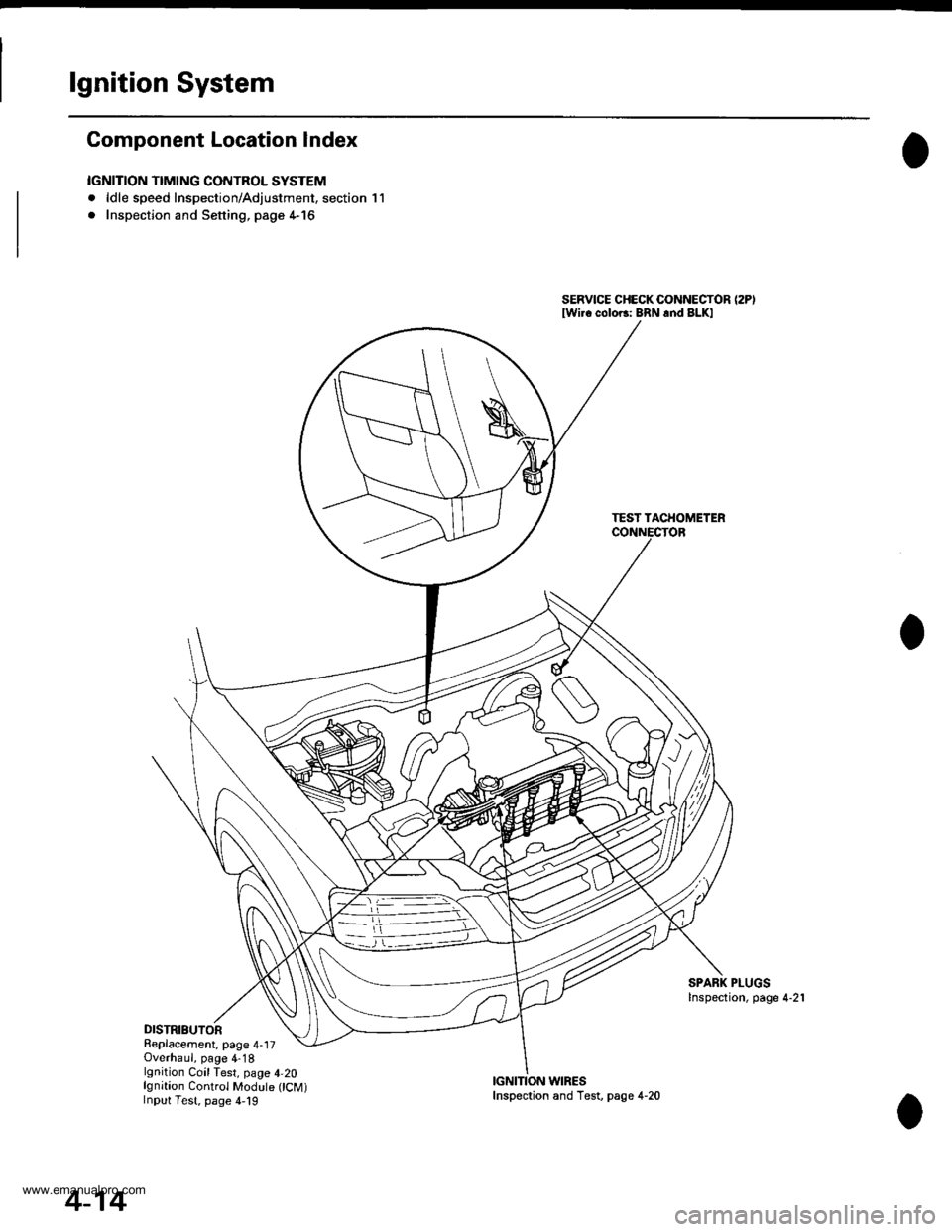
Component Location Index
IGNITION TIMING CONTROL SYSTEM
. ldle speed Inspection/Adjustment, section 11
. Inspection and Sening. page 4-16
DISTRIBUTORReplacement, page 4-17Overhaul, page 4-18lgnition CoilTest, page 4,20lgnition Control Module CM)Input Test, page 4,19
SERVICE CHECK CONNECTOR (2P)
lwi.c colo6: BRN rnd BLKI
TEST TACHOMETER
SPARK PLUGSInspection, page 4-21
WIRES
4-14
Inspection and Test, page 4-20
www.emanualpro.com
Page 67 of 1395
e
o
I'
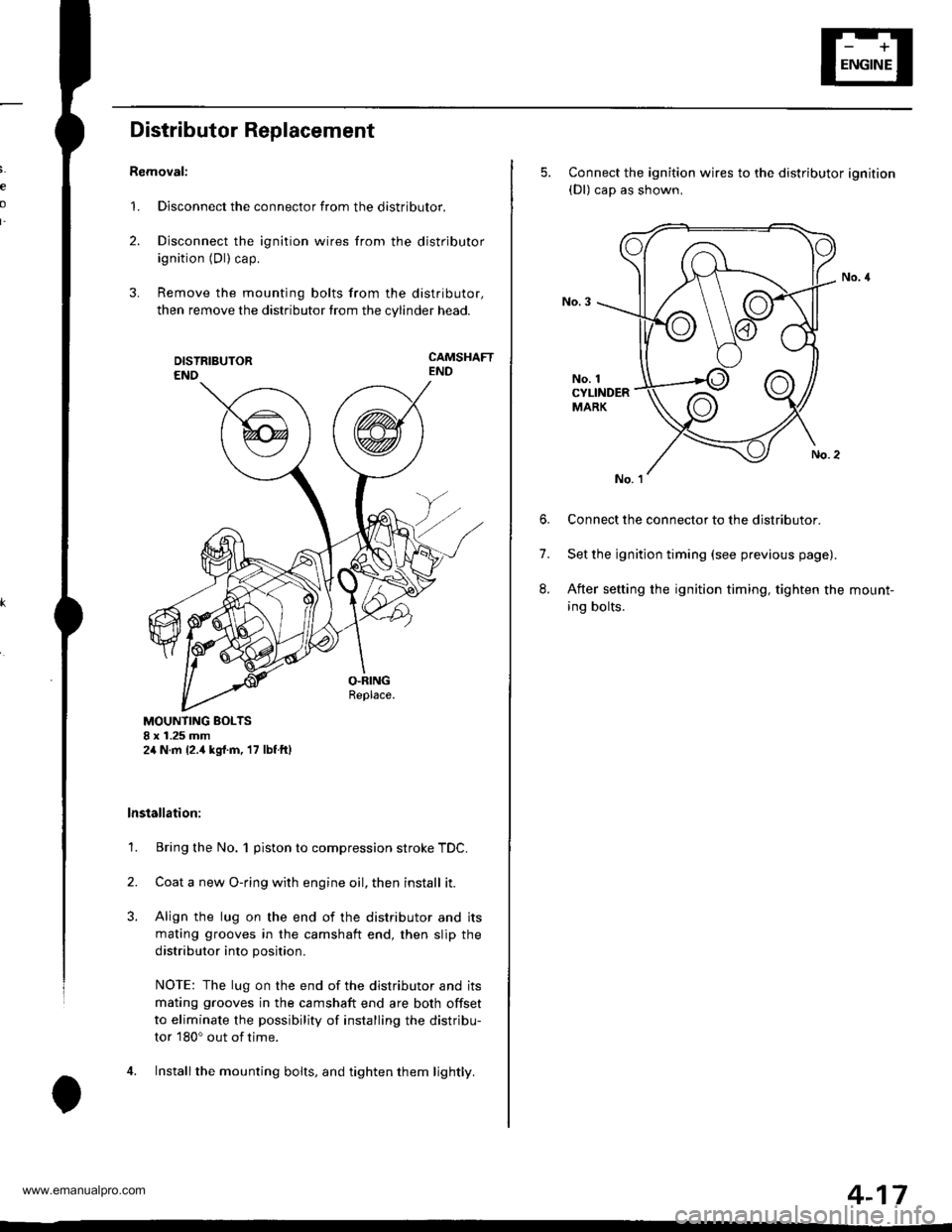
Distributor Replacement
Removal:
1. Disconnect the connector from the distributor.
2. Disconnect the ignition wires from the distributor
ignition (Dl) cap.
3. Remove the mounting bolts from the distributor,
then remove the distributor from the cylinder head.
CAMSHAFTEND
MOUNTING BOLTS8 x 1.25 mm2,1N.m {2.,1kgrf.m, 17 lbf ftl
lnstallation:
1. Bring the No. 1 piston to compression stroke TDC.
2. Coata new O-ring with engine oil, then install it.
3. Align the lug on the end of the distributor and its
mating grooves in the camshaft end, then slip the
distributor into position.
NOTE: The lug on the end of the distributor and its
mating grooves in the camshaft end are both offset
to eliminate the possibility of installing the distribu-
tor 180o out of time.
4. Installthe mounting bolts, and tighten them lightly.
5. Connect the ignition wires to the distributor ignition(Dl) cap as shown,
No. 1CYLINDERMARK
6. Connect the connector to the distributor.
7. Set the ignition timing (see previous page).
8. After setting the ignition timing, tighten the mount-
ing bolts.
4-17
www.emanualpro.com
Page 68 of 1395
lgnition System
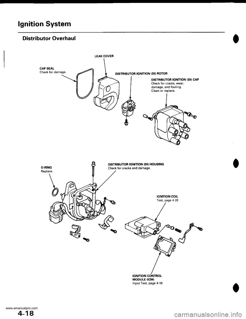
Distributor Overhaul
CAP SEALCheck for damage.DISTRIBUTOR IGNITION IDII ROTOR
OISTRIBUTOR IGNITION {DII CAPCheck for cracks, wear,damage, and to!ling.Clean or replace.
O.RINGReplace.
b
OISTBIBUTOR IGI{ITION IDO HOUSING
Check for cracks and damage.
IGNITION COILTest, page 4 20
@_
IGNITION CONTROLMODULE {ICMIInput Test, page 4-19
LEAK COVEN
4-18.
www.emanualpro.com
Page 72 of 1395
Charging System
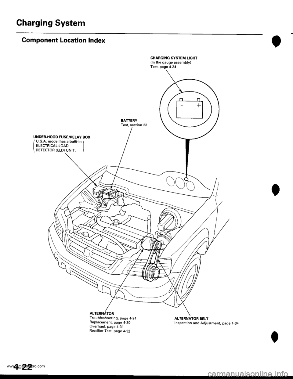
Component Location Index
ALTERNATOR
CHARGING SYSTEM LIGHT(ln the gauge assembly)Test, page 4-24
BATTERYTest,
Troubleshooting, page 4-24Replacement, page 4-30Overhaul, page 4-31Rectifjer Test, page 4,32
ALTERNATOR BELTInspection and Adjustment, page 4 34
4-22
www.emanualpro.com
Page 74 of 1395
Gharging System
Troubleshooting
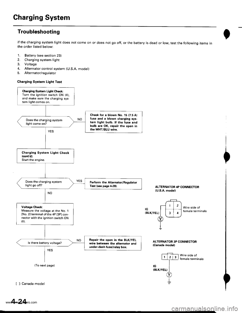
lf the charging system light does not come on or does not go off, or the battery is dead or low, test the following items inthe order listed below:
1. Battery (see section 23)
2. Charging system light
3. Voltage
4. Alternator control system (U.S.A. model)
5. Alternator/regulator
Charging System Light Test
ALTERNATOR 4P CONNECTOR{U.S,A. modell
(BLK/YEL)
2
3
Wire sade offemale terminals
I
I
I
ALTERNATOR 3P CONNECTORlCaneda model'
Iemale terminals
[ ]: Canada model
Chsrging Systom Light Check:Turn the ignition switch ON {ll),and make sure the charging system light comes on.
Check for a blown No. 15 17.5 Alfuse and a blown charging sys-tem light bulb. lf the tusa .ndbulb are OK, repair th€ open inth€ WHT/BLU wire.
Does the charging systemlight come on?
Charging System Light Check{com'd}:Start the engine.
Does the charging systemlight go offfPerform the Alte.nator/RegulatorTest lsee page +281.
Voltage Check:Measure the voltage at the No. IlNo. 2iterminal of the 4P [3Plcon-nector with the ignition switch ON{ ).
Ropair the open in the BLK/YELwiae betwoen the altemator andunder-da3h luso/relay box.
ls there battery voltage?
(To next page)
4-24
www.emanualpro.com
Page 75 of 1395
![HONDA CR-V 1999 RD1-RD3 / 1.G User Guide
in(From previous page)
Does the charging systemlight come on?
Ch6ck the L circuil:1. Turn the ignition switch OFF.2. Disconnect the 4P [3P] con-nector from the alternator.3. Turn the ignition switch HONDA CR-V 1999 RD1-RD3 / 1.G User Guide
in(From previous page)
Does the charging systemlight come on?
Ch6ck the L circuil:1. Turn the ignition switch OFF.2. Disconnect the 4P [3P] con-nector from the alternator.3. Turn the ignition switch](/img/13/5778/w960_5778-74.png)
in(From previous page)
Does the charging systemlight come on?
Ch6ck the L circuil:1. Turn the ignition switch OFF.2. Disconnect the 4P [3P] con-nector from the alternator.3. Turn the ignition switch ON (ll).
Repair the short to ground in theWHT/BLU wire.
[ ]: Canada model(cont'd)
4-25
www.emanualpro.com
Page 78 of 1395
Gharging System
Troubleshooting (cont'd)
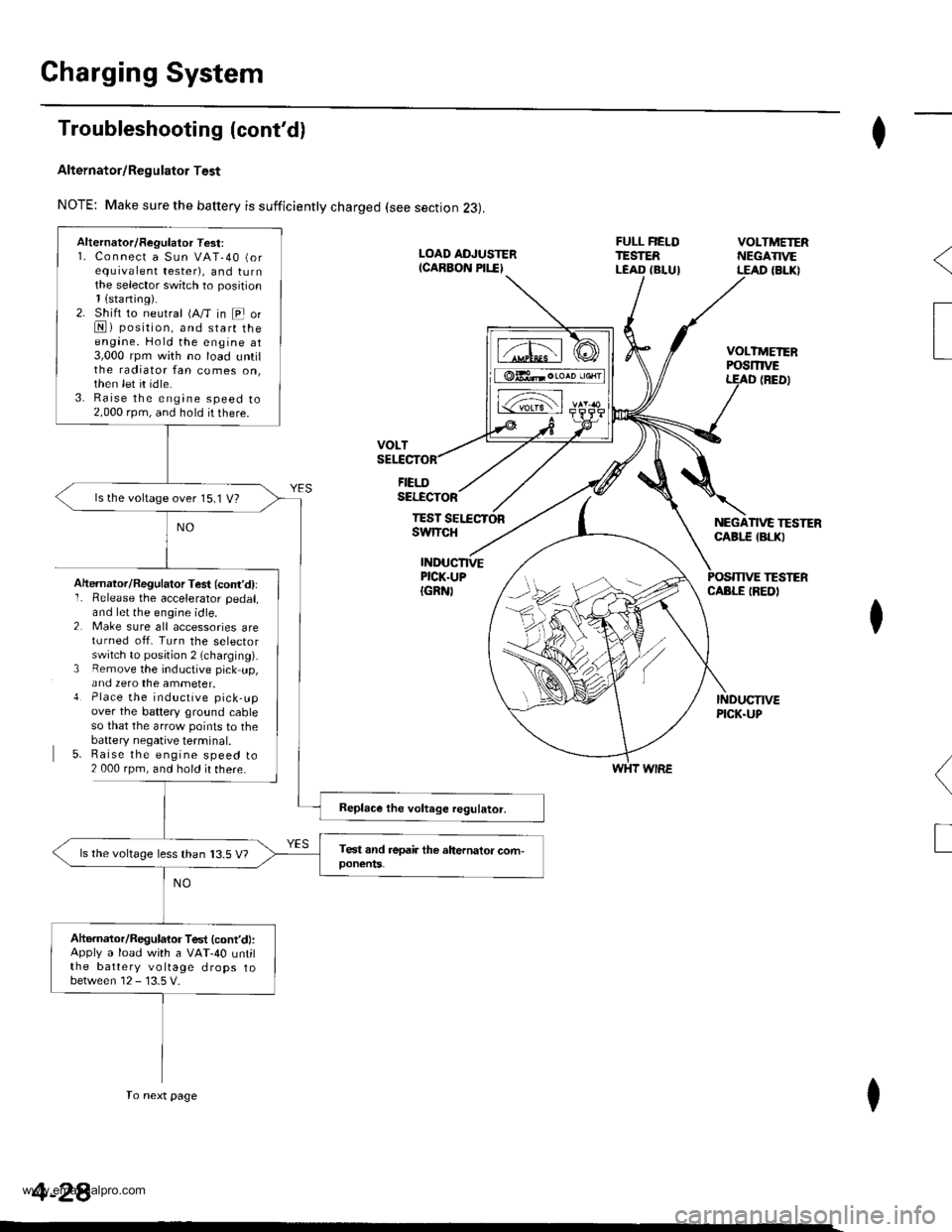
Alternator/Regulator Test
NOTE: Make sure the battery is sufficiently charged (see section 23).
FIELDSELECTOR
TESTswtTcH
I
VOLTMEIERPOSmVEt
NEGATIVE TESTERCABI.E {BLKI
(BED)
TESTERINDUCTIVEPICK.UP{GRN)CABLE IREDIAhernator/Regulator Test (cont'd)lI� Release the accelerator pedal,and let the engine idle.2 Make sure all accessories areturned off. Turn the selectorswitch to posjtion 2 (charging).3 Remove the inductive pick up,and zero the ammeter.{ Place the inductive pick-upover the battery ground cableso that the arrow points to thebaftery negative terminal.5. Raise the engine speed to2 000 rpm, and hold ir there.
I
(
T
I
WHT WIRE
Alternator/Regulator Test:1. Connect a Sun VAT-40 (orequrvalent tester), and turnthe selector switch to position1{sraning).2. Shift to neutral (A/T in E orN) position, and start theengane. Hold the engine at3,000 rpm with no load untilthe radiator fan comes on,then let it idle.3. Raise the engine speed to2,000 rpm, and hold it there.
ls the voltage over 15.1 V?
ls the voltage less than 13.5 V?
Altarnator/Regulator Test (cont'd:Apply a load with a VAT-40 untilthe battery voltage drops tobetween 12 - 13.5 V.
To next page
4-28
www.emanualpro.com
Page 79 of 1395
From previous page
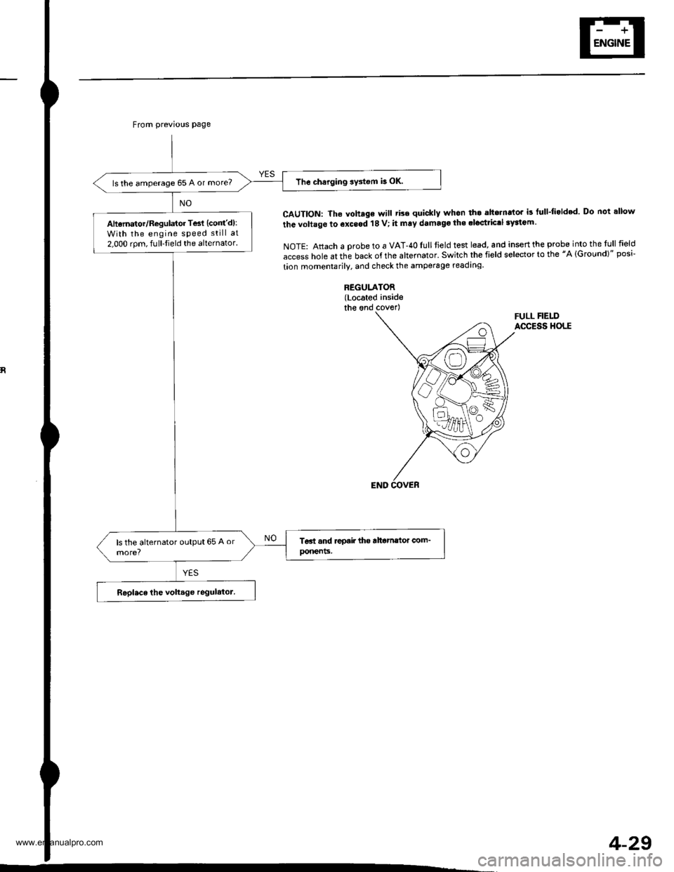
The charging sy3tem b OK.ls the amperage 65 A or more?
Aharnator/Regulator Tesl (cont'd):
With the engine speed still at
2.000 rom, fulllield the alternator.
CAUTION: The voh.ge will tise quickly whon th. ahornato. is tull-li.lded Do not allow
the voltage to exceod 18 V; it mry damago the .loctrictl 3yaiGm.
NOTE: Attach a probe to a VAT-40Iull tield test lead, and inseft the probe into the tull field
access hole at the back of the altemator' Switch the field selector to the "A lGround)" posi-
tion momentarily. and check the amperage readrng.
REGULATOR(Located insidethe ond coverlFULL FIELDACCESS HOLE
4-29
www.emanualpro.com
Page 80 of 1395
Charging System
Alternator Replacement
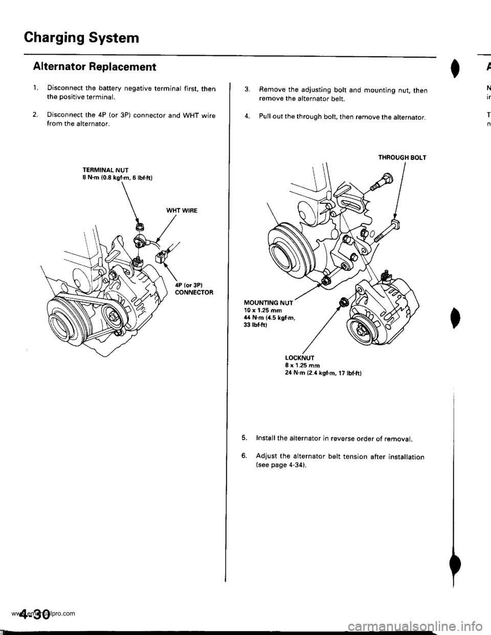
't.Disconnect the battery negative terminal first, thenthe positive terminal.
Disconnect the 4P (or 3P) connector and WHT wirefrom the alternator.
WHT WIRE
4-30
'll
Remove the adjusting bolt and mounting nut, thenremove the alternator belt.
Pull out the through bolt, then remove the alternator.
THROUGH BOLT
ll^I}v
N
ir
T
n
MOUNTING NUT10 x 1.25 mm44 N.m 14.5 kgf.m.33 tbtfttt
o.
LOCKNUT8 x 1 .25 mm24 N.m (2.4 kgt m, 17 lbl.ft,
Install the alternator in reverse order of removal.
Adjust the alternator belt tension after installation(see page 4-34).
www.emanualpro.com
Page 81 of 1395
,T
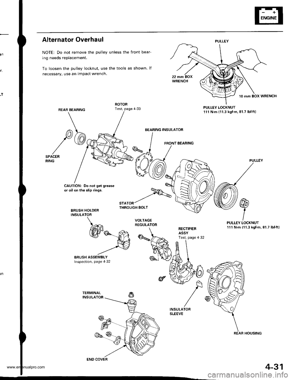
Alternator Overhaul
NOTE: Do not remove the pulley unless the front bear-
ing needs replacement.
To loosen the pulley locknut, use the tools as shown. lf
necessary, use an impact wrench.
PULLEY LOCKNUT111 N.m (11.3 kgf.m,81.7 lbf.ft)
FRONT BEARING
CAUTION: Do not get grease
or oil on the slip rings.
BRUSH HOLDERINSULATOB
"'^.^t%THROUGH BOLT
PULLEY
PULLEY LOCKNUT111 N.m {11.3 kgf.m, 81.7 lbf,ft)RECTIFIERASSYTest. page 4 32
PULLEY
BEARING INSULATOR
COVER
REAR HOUSING
4-31
www.emanualpro.com