Page 920 HONDA CR-V 1999 RD1-RD3 / 1.G User Guide
[x] Cancel search | Manufacturer: HONDA, Model Year: 1999, Model line: CR-V, Model: HONDA CR-V 1999 RD1-RD3 / 1.GPages: 1395, PDF Size: 35.62 MB
Page 1105 of 1395

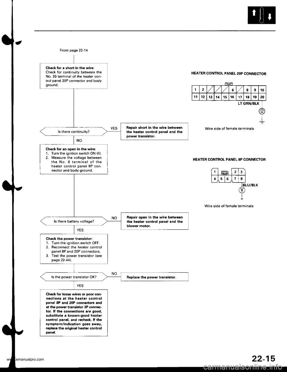
From page 22-14
Chock for a short in the wire:Check tor continuity between theNo. 20 terminal of the heater con'trol panel 20P connector and bodyground,
R.p.ir short in the wire betwoenth. herter control Denel snd theoowor tranSastor.
Check to. an open in the wire:1. Turn the ignition swilch ON (ll).
2. Measure the voltage betweenthe No. I terminal of theheater control panel 8P con-nector and body ground.
Repair opan in the wire betwaentho heatsr cont.ol o.nel and theblower motor.ls there battery voltage?
Chock th6 power iransistor:1. Turn the ignition switch OFF.2. Reconnect the heater controlpanel 8P and 20P connectors.3. Test the power transistor (seepage 22 44).
ls the power transistor OK?
Chec* for loo3e wires or Door oon-neclions at the heater controlpanel 8P and 20P connoctors andat lhe power tran3istor 3P connec-tor. lf lhe connectiorc are good,substituta , known-good hoatercontrcl pan6l, and r€check. ll thesymptom/indication goes away.replecg th6 original heater controloanel.
HEATER CONTROL PANEL 2OP CONNECTOR
2,/1,/l/68910
1112131a151617181920
LT GRN/BLK
o
Wire side of female terminals
HEATER CONTROL PANEL 8P CONNECTOR
BLU/8LK
Wire side of female terminals
1
4678
22-15
www.emanualpro.com
Page 1111 of 1395

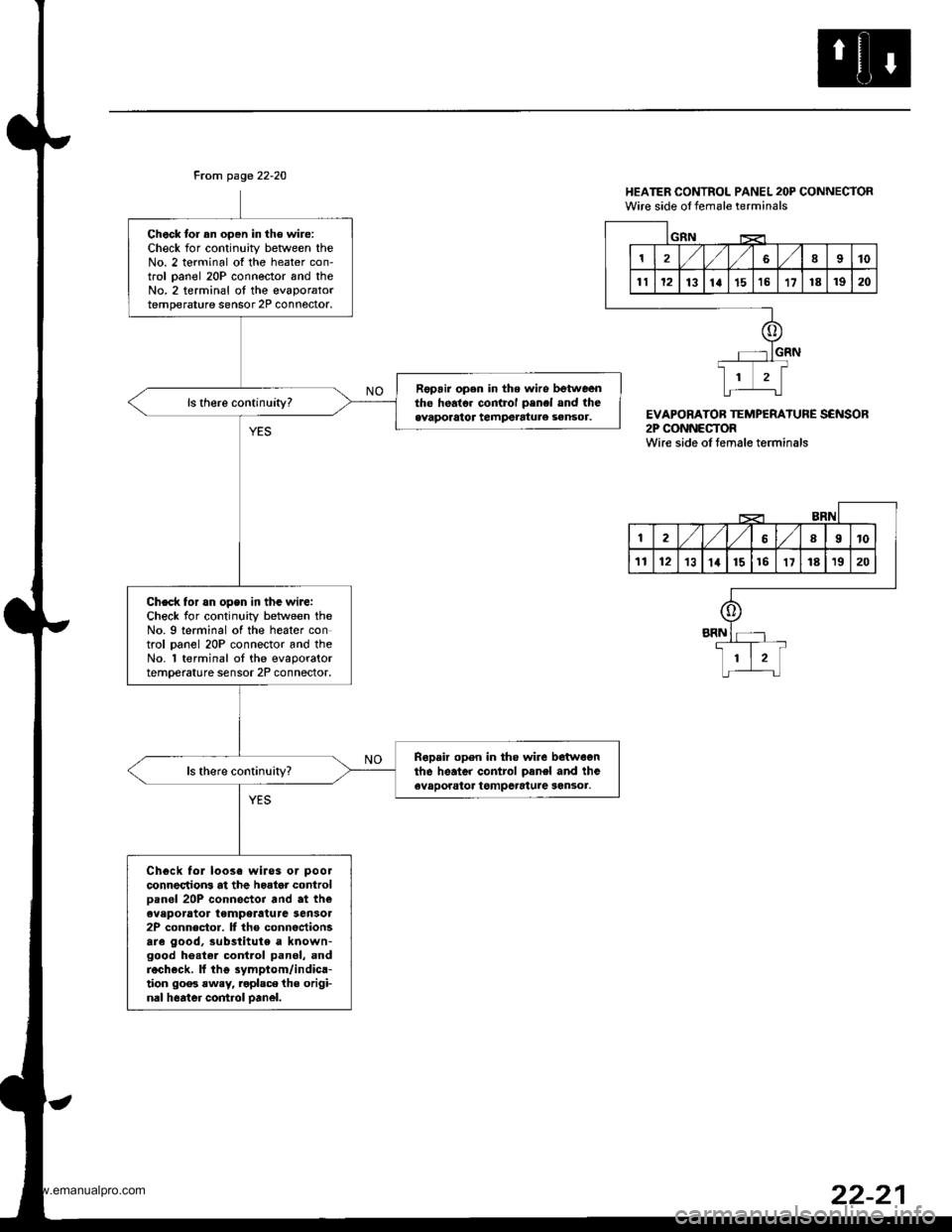
From page 22-20
Chock tor an oDen in th€ wire:Check for continuity betlveen theNo. 2 terminal of the heater con-trol oanel 20P connector and theNo.2 terminal oI the evaporatortemperature sensor 2P connoctor.
Fopair open in the wiro betweentho heato. control penel and theevaporator tempetatule sensor.
Check for rn opsn in tha wiJe:Check for continuity between theNo. 9 terminal of the heater control oanel 20P connector and theNo. 'l terminal ot the evaporatortemperature sensor 2P connector,
Ropair open in tho wire betwegnthe heater control oanel and theevaporator tgmpcrature sen3or.
Chgck fol loose wiros or pool
connectrons at the hoator controloan6l 20P connector and at theeveporator temperatura Sensol2P connector. It the connectionsare good, substitute a known-good he.tel contlol panel, andrech€ck. ll thg symptom/indica-tion 90o3 rwey, roplsce the origi-nal heater control oanel.
HEATER CONTROL PANEL 2OP CONNECTORWire side ol female terminals
EVAPORATOB TEMPERATURE SENSOR2P CONNECTORWire side oI temale terminals
1810
1112131a1516't7181920
GIIN
12,/ l,/689t0
'tl1213lat1516'1718't920
o
+
li-L:t
www.emanualpro.com
Page 1113 of 1395

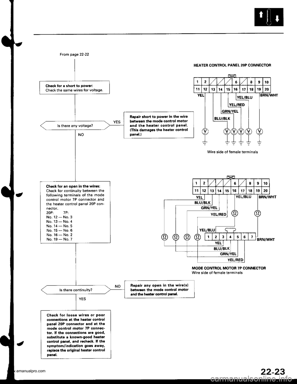
From page 22-22
Chgck for a short to power:
Check th6 same wires lor voltage.
Ropair lhort to powor in the wiiobetw6an tho mode comrol motorend thc hoat.r cont.ol pan.l.(This damagF tha h€ator Gontrolpancl.l
Chack for an opon in tha wiles:Check lor continuity between thefollowing terminals oI the mode
control motor 7P connector andthe heater control panol 20P con-nector.20Pt 7P.No. 12 - No. 3No. '13 - No. 4No. 14- No.5No. 15 - No. 6No. t6 - No. 2No. 19 - No. 7
R.pair any opon in tho wilols)betwaen th6 modg cortrol motorand th. heatar control p.nsl.
Chock fo. loose wiret or pool
connections at the heat6r controlpancl 20P connector and tt themodo control motor 7P connoc-tor. lf tho connactions sre good,
substitute a known-good hortcrcontrol pan6l, and tech.ck. lf thesymptom/indication goes awaytroplaco tho original hcater @nttolp3nel.
HEATER CONTROL PANEL 2OP CONNECTOR
12'VVLgl8910
't112rslrrlrslre17181920
8LU/BLX
:L/BLUBRN/WHT
BRN/WHT
BRN/WHT
Wire side ot female terminals
MODE CONTROI- MOTOR 7P CONNECTORWire side ol temale terminals
2,/1,/l/II10
111213t14t151511181920
BLU/BL
GRi
YEL/
Kt I I|/YEL I IIYEL/REDI
t-BLUI q
;f;T;T;
YEL/BLU
YEL
BLU/BLK
GRN/ItEL
YI:L/FED
22-23
www.emanualpro.com
Page 1129 of 1395

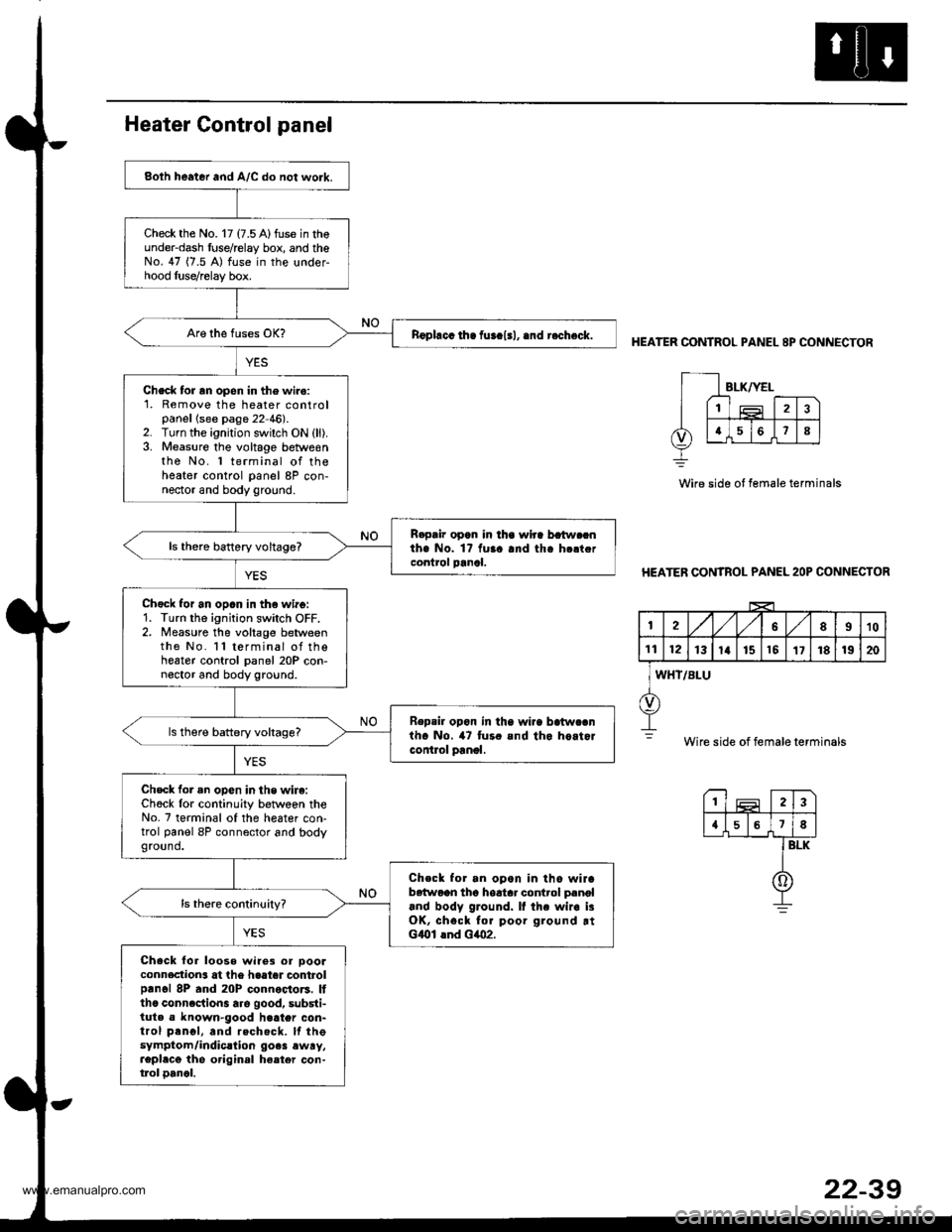
Both heater and A/C do not work.
Check the No. 17 (7.5 A)fuse in theunder-dash fuse/relay box, and theNo. 47 (7.5 A) fuse in the under-hood luse/relay box.
nophcc ih. fur.l.l, .nd r.check.
Check tor rn open in the wiro:1. Remove the heater controlpanellsee page 22 46).2. Turn the ignition switch ON (ll).3. Measure the voltage betweenthe No. 1 terminal of theheater control panel 8P con-nector and body ground.
R.pair opan in lha wlra batw.cnthe No. 1? fuaa and tha h.ltcrcontrol panal.ls thero battery voltage?
Chgck for an opan in th€ wirg:1. Turn the ignition switch OFF.2. Measure the voltage betweenthe No. l l terminal of thoheater control panel 20P con-noctor and body ground.
Repsil opon in tha wi.a batwcanth. No. 47 tur. and tho hoitorcontlol panol.
ls there battery voltags?
Check for an opon in the wire:Ch6ck lor continuity betwoen theNo. 7 terminal of the heater con-trol panel 8P connector and bodyground.
Check for an opon in tho wirab6{woon tho hoatar control p.noland body ground. It the wir. i3OK, chsck for poor ground rtGlOl lnd Glo2.
Check for loose wire3 or oooaconnection3 at the haater controlprnol 8P and 20P connoctors. Itthc conncction3 are good, substi-tuta a known-good h€ater con-trol prnol, and rechecft. lf thesymptom/indic.lion go.3 ewry,repl.cg the original ha.ter con-tlol oancl.
HEATER CONTROL PANEL 8P CONNECTOR
Wire side ot female terminals
HEATER CONTROL PANEL 2OP CONNECTOR
I2A,/1,/58910
1t12131a151517181920
WHT/BLU
Wire side of female terminals
23
{578
BLK
0
www.emanualpro.com