Page 920 HONDA CR-V 1999 RD1-RD3 / 1.G Workshop Manual
[x] Cancel search | Manufacturer: HONDA, Model Year: 1999, Model line: CR-V, Model: HONDA CR-V 1999 RD1-RD3 / 1.GPages: 1395, PDF Size: 35.62 MB
Page 289 of 1395
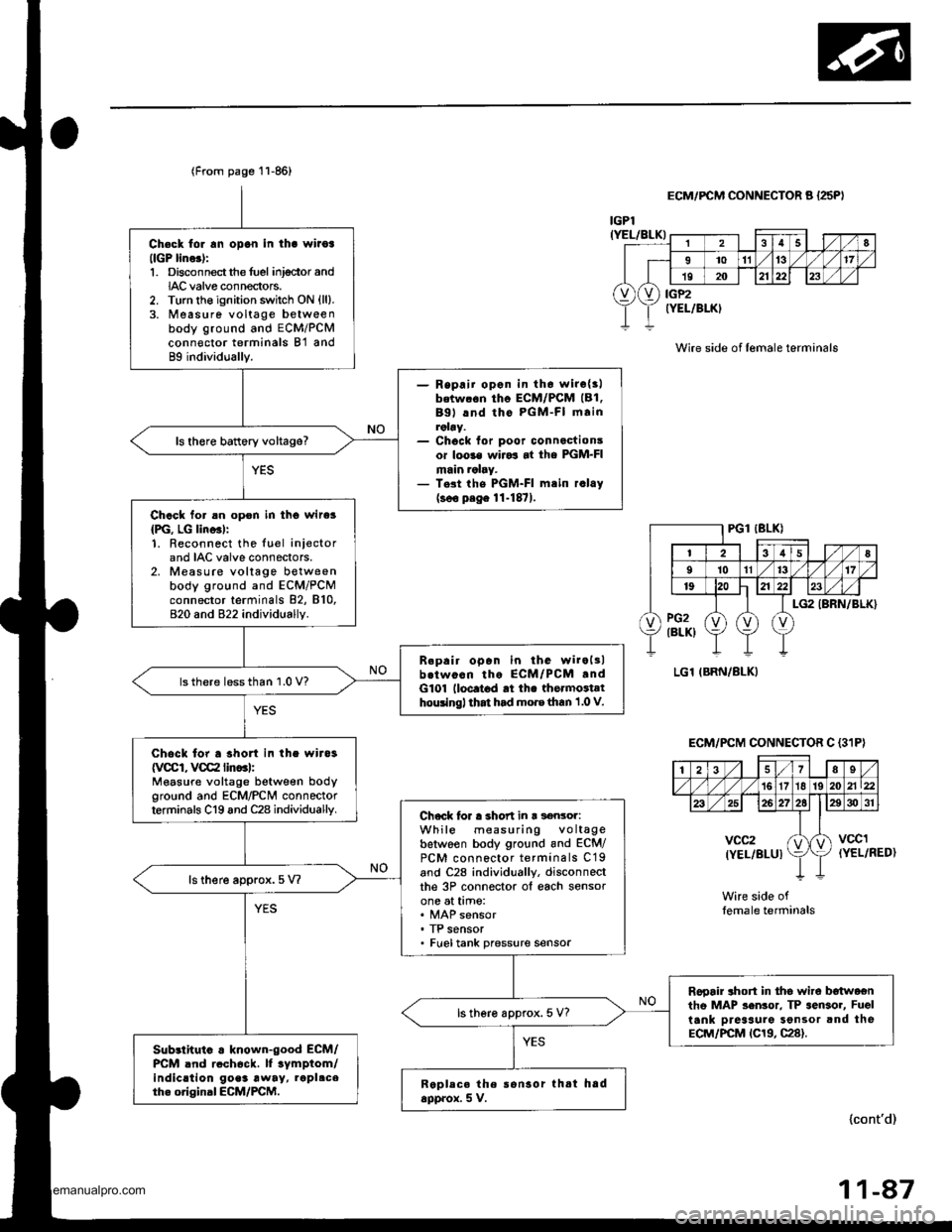
Ch€ck tor rn opon in tha wiioa(lGP lino.):1. Disconnectthe fuel inj€ctor andIAC valve connectors.2. Turn the ignition switch ON {ll}.3. Measure voltage betweenbody ground and ECM/PCMconn€ctor terminals B'l and89 individually.
- Repaii opon in th6 wirc{3lbetw.6n tho ECM/PCM (B1.
Bgl lnd tho PGM-FI mainroby.- Chock for poor connactionsor loo3€ wiJo3 at the PGM-FImain ralry.- T.st the PGM-FI mtin r.lay(soo p.ge 11-1871.
ls there battery voltage?
Chack for an opon in tho wire3
{PG, LG lino3l:1. Reconnect the luel iniectorand IAC valve connectors.2. Measure voltage betweenbody ground and ECM/PCMconnector terminals 82, 810,820 and 822 individually.
B.pair open in the wiroltlb.twocn tho ECM/PCM .ndG101 lloc.t6d rt th. thormoiathouingl that had mo.e than 1 .0 V.
lsthere lessthan 1.0 V?
Chock for a shon in the wira3
{VCCI, VCC2 lin..l:Measure voltage between bodyground and ECM/PCN4 connectorterminals C19 and C28 individuallv.Chock lor a short in r s€nsor:While measuring voltagebetwoen body ground and ECM/PCM connector terminals C19and C28 individually, disconneclthe 3P connector ol each sensorone at time:
. TP sensor. Fueltank pressure sensor
ls there approx.5 V?
Rooair ahort in tho wire b€twoentho MAP sen3or. TP sensor, Fuel
tank Dreaaure Sonsor and theECM/PCM tC19, C28).
ls there approx. 5 V?
Sub3lhuio . known-good ECM/PCM .nd rcch6ck. lf tymptom/indic.tion go.3 away, rapl.ceth. original ECM/PCM.Replece the ronsor thtt hadapprox. 5 V.
(From page 11-86)
lcont'd)
r
28
I1011't317
19202123
vXv) iiP2rELlBLK)
IGPl(YEL/BLK)
ECM/FCM CONNECTOR A {25PI
Wire side of lemale terminals
(YEL/RED)
Wire side oflemale terminals
ECM/PCM CONNECTOR C {3'IP}
| 2i37Es/'t61718 192021\22
26272elE30 31
vcc2(YEL/BLUIktvccl
11-47
www.emanualpro.com
Page 304 of 1395
PGM-FI System
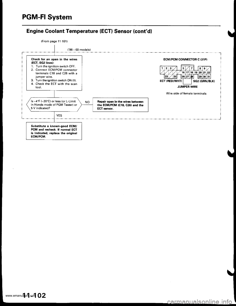
Chack lor an open in the wires(ECT, SG2 lines):1. Turn the ignition switch OFF.2. Connect ECM/PCM connectorterminals C18 and C26 with a
3. Turn the ignition switch ON (ll).
4. Check the ECT with the scantool.
ls -4"F (-20"C) or less (or L-Limitin Honda mode of PGM Testerlor5 V indicated?
Ralpair open in tho wir6s b6twe€ntho ECM/PCM 1C18, c26l 6nd thoECT sensor.
Substitute a known-good ECM/PCM and rech.ck. lf normal ECTis indicrted, replace ths originslECM/PCM.
Engine Goolant Temperature (ECTI Sensor (cont'dl
(From page 11 101)
ECM/PCM OONNECTOR C 13lPI
(GRN/BLK)
JUMPER WIRE
Wire side of temale terminals
17I9
,/ 1617't8'1920n
ECT IRED/WHTIsG2
11-102
www.emanualpro.com
Page 346 of 1395
PGM-FI System
Grankshaft Speed Fluetuation (CKFI Sensor (cont'dl
.98 - 00 modols:
CKF SENSOR 2P CONNECTOR IClO'I
r-:-i-_ltr_- |l1 2ll,,-'CKF P I ICKF MtsLuneotTOl wlrrneo)\7
Terminal side of male terminals
r:l
t! El
.KFP XA"*."talu rneor \:f
f rwxvneor
ECM/PCM CONNECTOR C (31P)
CKF PIBLU/REDI
CKF M(WHT/BEOI
Wi16 side of l6male terminals
1278__l
-lI(o
T
161716't9202122
,/ 2s262728293()3l
M
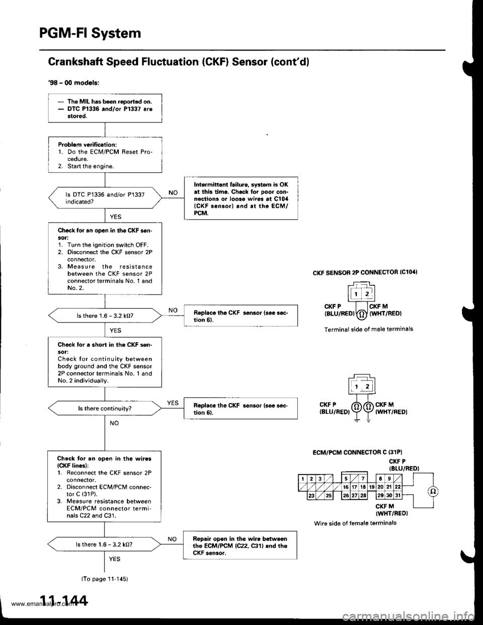
- The MIL has boon reported on.- DTC P1336 and/or P1337 arestored.
ProblGm verification:1. Do the ECM/PCM Reset Pro-cedure,2. Stan the engine.
Inte.mittant failuro, 3y*om b OKat thb tima. Chack lor ooor con-nections or looso wirea at C10a{CKF sensorl and.t the ECM/PCM,
Chgck forun open in tho CKF son-sori1. Turn the ignition switch OFF.2. Disconnect the CKF sensor 2Pconnector.3. Measure the resistancebetween the CKF sensor 2Pconnector terminals No. 1 andNo.2.
lsthere 1.6 - 3.2 kO?
Check for a short in the CKF sen-
Check lor continuity betweenbody ground and the CKF sensor2P connector terminals No. 1 andNo.2 individually.
Check for an open in the wiresICKF linca):1. Feconnect the CKF sensor 2Pconnector.2. Disconnect ECM/PCM connec-tor C (31P).
3. Measure resistance betweenECM/PCM connector termi'nals C22 and C31.
Repair opon in the wir6 botwoonthe ECM/PCM 1C22, glll lnd th6CKF s6n3or.
ls there 1.6 - 3.2 kO?
(To page 11'1451
11-144
www.emanualpro.com
Page 392 of 1395
Fuel Supply System
PGM-FI Main Relay (cont'dl
('98 - 00 models)-l
(From page 11,188)
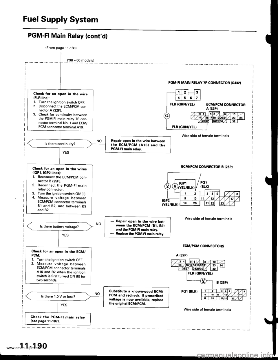
Check lor an open in the wire(FLR line):1. Turn the ignition switch OFF.2. Disconnect the ECM/PCM connector A (32P1.3. Check for continuity betweenthe PGM-FI main relay 7P con-nector terminal No. '1 and ECM/PCM connector terminal 416.
Repaia open in the wire betweenthe EcM/PcM lAl5l .nd thePGM-FI m.in relay.
Check for an open in the wiresllcPl,lGP2linos):1. Reconnect the ECM/PCN4 con-nector I (25P).2. Reconnect the PGM Fl mainretay connector.3. Turn the ignition switch ON l).4, Measure voltage betweenECM/PCM connector terminalsB1 and 82, and between 89and 82.
Ropai. open in tho wire b6t-we€n th. ECM/PCM lBt, Btl.nd the FGM-FI main rd.y.R€plac€ th6 FGM+| main retay,
Chock for an open in the ECM/PCM:1. Turn the ignition switch OFF.2, Measure voltage betweenECM/PCM connector terminals416 and 82 when the ignitionswitch is first turned ON (tl) for
Subrtitute e known-good ECM/PCM and recheck. lf prescribsdvoltage b now ovrihble, replacothe originel ECM/PCM.
ls there 1.0 V or less?
Check the PGM-FI main.elav(s6e page 11-1871.
PGM.FI MAIN RELAY 7P CONNECTOF (C€2)
Wire sid€ of female terminals
ECM/PCM CONNECTOR B I25PI
IGP2(YEL/BLKI
ECM/PCM CONNECTORS
a t32Pl
Wire side of female terminals
Wire side of f€male terminsls
1 1-190
Dde"Jt;;liL-F-T--
PGl(BLK}
38s l1011131719202122
www.emanualpro.com
Page 418 of 1395
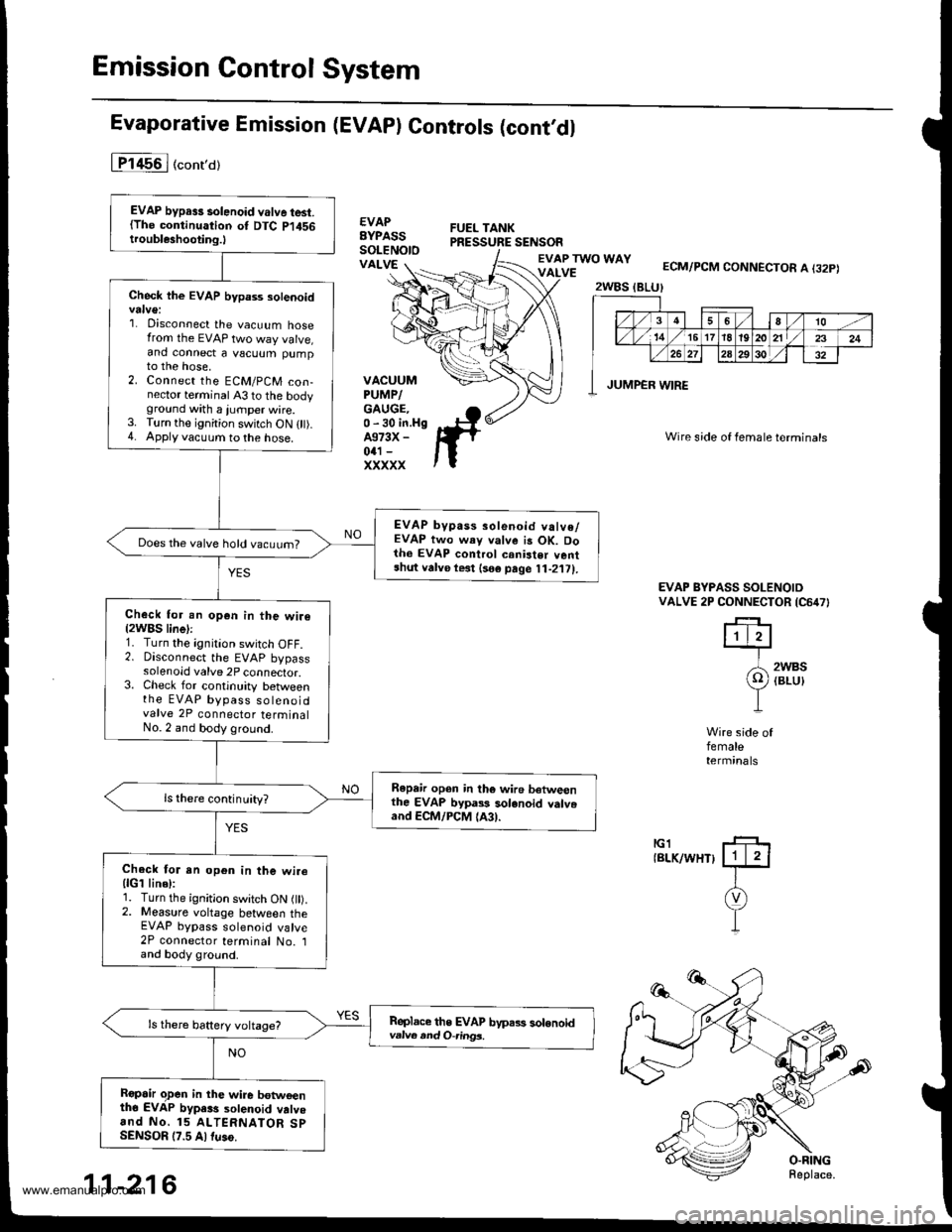
Emission Control System
Evaporative Emission (EVAPI Controls (cont,dl
1T1456I (conro)
€VAPBYPASSSoLENOtOVALVEECM/PCM CONNECTOR A I32P)
Wire side of female terminals
VACUUMPUMP/GAUGE.0 -30 in.HgA373X -
041 -
xxxxx
EVAP BYPASS SOLENOIDVALVE 2P CONNECTOR lcorlTl
2WBS(BLU}
II
Wire side offemaletermrnats
tGlIBLK/WHT}
EVAP bypa3s solenoid valve test.(The continuation ot DTC P1456troubleshooting.l
Check the EVAP bypass sotenoid
1. Disconnect the vacuum hosefrom the EVAP two way valve,and connect a vscuum pumpto the hose,2. Connect the ECM/PCM con-nector terminal 43 to the bodyground with a jurnper wire.3. Turn the ignition switch ON 0t).4. Apply vacuum to the hose.
EVAP bypass solenoid valve/EVAP two way valve is OK. Doth6 EVAP control crnister ventshut vafve le3t lso€ page 11-2'111.
Does the valve hold vacuurn?
Check for an op€n in the wir€(2WBS line):1. Turn the ignition switch OFF.2. Disconnect the EVAP bypasssolenoid valve 2P connector.3. Check for continuity betweenthe EVAP bypass so teno idvalve 2P connector terminalNo. 2 and body ground.
Repair open in the wire betweenthe EVAP bypass solenoid valv.and ECM/PCM lA3).
Chack tor an op6n in the wirellcl line):1. Turn the ignition switch ON l).2. Measure voltage between theEVAP bypass solenoid valve2P connector terminal No. land body ground.
Replace the EVAP byps.,s solonoidvatus and O-ring3.
Ropair o,pen in the wire botwoenth6 EVAP bypa$ sotenoid vatvoand No. 15 ALTERNATOR SpSENSOR (7.5 Altuso.
2WBS (BLU}
/3
7,x
4l6o/to -/
,/ 16 1718't920 211/z3
26 272A29solT32
JUMPER WIRE
11-216
www.emanualpro.com
Page 424 of 1395
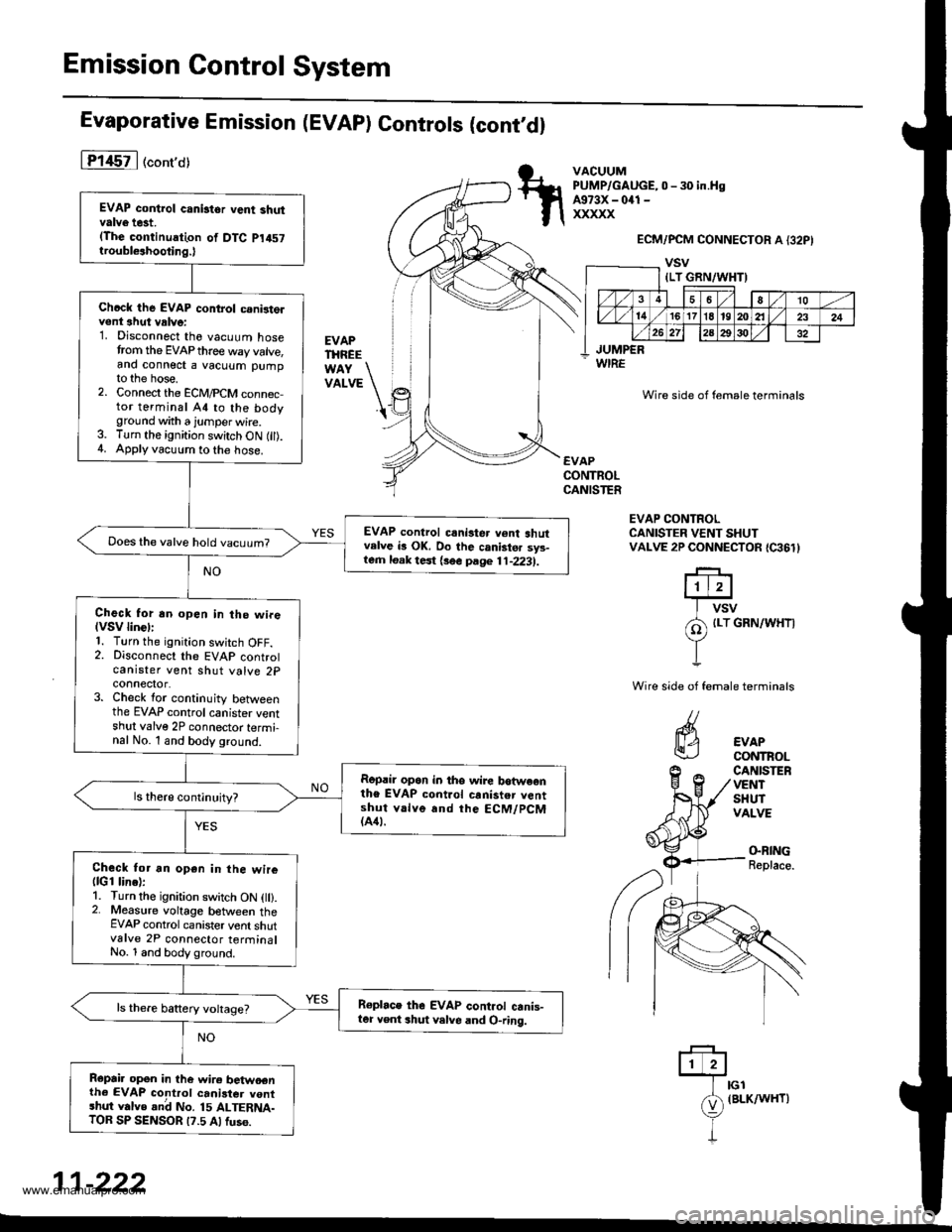
Emission Control System
Evaporative Emission (EVAP) Controls (cont,dl
lT145il ("ont'o)
EVAPTHREE
VATVE \'t
VACUUMPUMP/GAUGE,0 - 30 in.HsA973X - 041 -
xxxxx
WIRE
ECM/PCM CONNECTOR A {32PI
vsv
Wire side of female terminals
EVAPCONTROLCANISTER
EVAP CONTROLCANISTER VENT SHUTVALVE 2P CONNECTOR {C361}
riErr+J
I vsv
/A {Lr GRN/WHT|
YI
Wire side of female terminals
CANISTEFVENTSHUTVALVE
EVAPCONTROL
(}BING
Replace.
ffilrcr
e
(BLK/wHr)
I
11-222
EVAP control canistor vent shutvalve t6t.(The continuation of DTC p1457
troubl€ahooting.)
Chcck the EVAP control c.nirt6lvent ahut vrlve:1. Disconnect the vacuum hosetrom the EVAP thre€ way valve,and connect a vacuum pumpto the hose.2. Connect the ECM,PCM conn6c,tor terminal A4 to the bodyground with a jumper wire.3. Turn the ignition switch ON fil).4. Applyvacuum to the hose.
EVAP control crni3ter v6nt shutvelve b OK. Do the canistsr sys-lern loak test {3ee page 11-2231.
Does the valve hold vacuum?
Check for an open in the wireIVSV linGll1. Turn the ignition swjtch OFF.2. Disconnect the EVAP controlcanister vent shut valve 2pconnector.3. Check for continuity betweenthe EVAP control canister ventshul valve 2P connector termi-nal No. l and body ground.
Ropril op6n in tho wire botweonthe EVAP control canister v6ntshut v.lve and the ECM/PCM(A41.
Check tor an open in the wire(lGl line):1. Turn the ignition switch ON l).2. Measure voltage between theEVAP control canister vent shutvalve 2P connector terrninalNo. 1 and body ground.
Roplace thG EVAP cont.ol canis-ter Yent shut velve and O-ring.
Repai. opon in the wire betwoenth6 EVAP control canister vontshut valve .nd No. 15 ALTERNA-TOB SP SENSOR t?.5 Alfus6.
{LT GRN/WHT)
36a10
l4/1617l8't9202l232426 272a2930
JUMPER
www.emanualpro.com
Page 634 of 1395
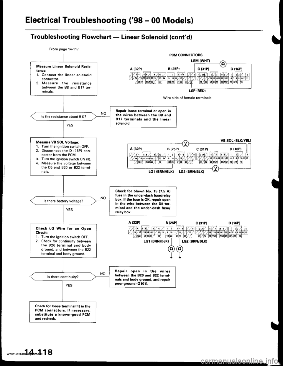
ElectricalTroubleshooting ('98 - 00 Models)
Troubleshooting Flowchaft - Linear Solenoid (cont'dl
Wire side of female terminals
LG2 {BRN/BLKI
From page 14-117
Measure Linea. Solenoid Resis-tance:1. Connect the linear solenoidconnector,2. Measure the resistancebetween the 88 and 817 termrnals,
Repair loose torminal oi open inthe wires between rhe 88 and817 terminals and the linearsolenoid.
ls the resistance about 5 O?
Measure VB SOL Voltago:1. Turn the ignition switch OFF.2. Disconnect the D 116P) con-nector trom the PCM.3. Turn the ignition switch ON (ll).4. Measure the voltage betweenthe D5 and 920 ot B22 tetmi-nals.
Check for blown No. 15 17.5 Alfuse in the under-da3h tus€/relaybox. lI the fuse is OK, rap.ir openin the wire betwe€n the D5 ter-minal and th€ under-dash tuso/relav box.
ls there baftery voltsge?
Check LG Wire for.n OpenCircuit:1. Turn the ignition switch OFF.2. Check for continuity betweenthe 820 terminal and bodyground, and between the 822terminal and body ground.
Repair op6n in the wirosbetwe€n the 820 and 822 termi-nals and body ground, and repairpoor g.ound iG101).
ls there continuity?
Chack tor loose terminel fit in thePCM connecto13. It nocosaary,substitute a known-good PCM.nd recheck,
a t32Plc t3lPl
LSP (REO)
a l32Pl
A (32P1
LGl IBRN/BLK}
B l2sP)c 13lPlD l16P)
14-118
www.emanualpro.com
Page 792 of 1395
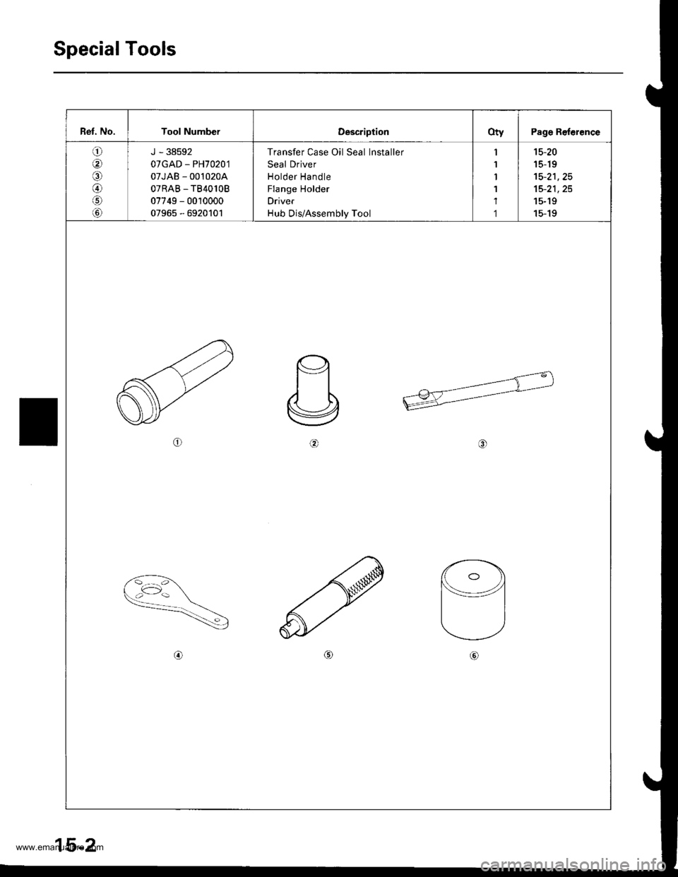
Special Tools
Ret. No.Tool NumberOescriptionotvPage Reler€nce
o
@aa
@/il
tol
J - 38592
07GAD - PH7020'1
07JAB - 0010204
OTRAB _TB40lOB
07749 - 0010000
07965 - 6920101
Transfer Case Oil Seal lnstaller
Seal Driver
Holder Handle
Flange Holder
Driver
Hub Dis/Assembly Tool
1
1
1
1
1
1
15-20
15-19
tc-zt, z9
15-21,25
15-19
15-19
6\
@
15-2
www.emanualpro.com
Page 1092 of 1395
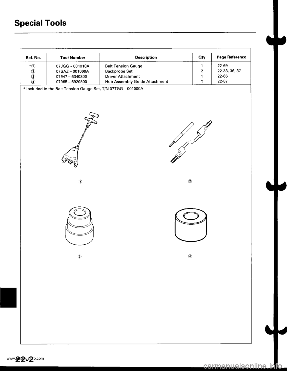
Special Tools
Rel. No. I Tool NumberDescriptionOty I Page Relerence
.o
6,
@
@
07JGG - 001010A
07sAz - 001000A
07947 - 6340300
07965 - 6920500
Belt Tension Gauge
Backprobe Set
Driver Attachment
Hub Assembly Guide Attachment
1
2
1
1
22-69
22-33,36,37
22-66
22-61
* Included in the Belt Tension Gauge Set, T/N 07TGG - 001000A
t
o
22-2
www.emanualpro.com
Page 1104 of 1395
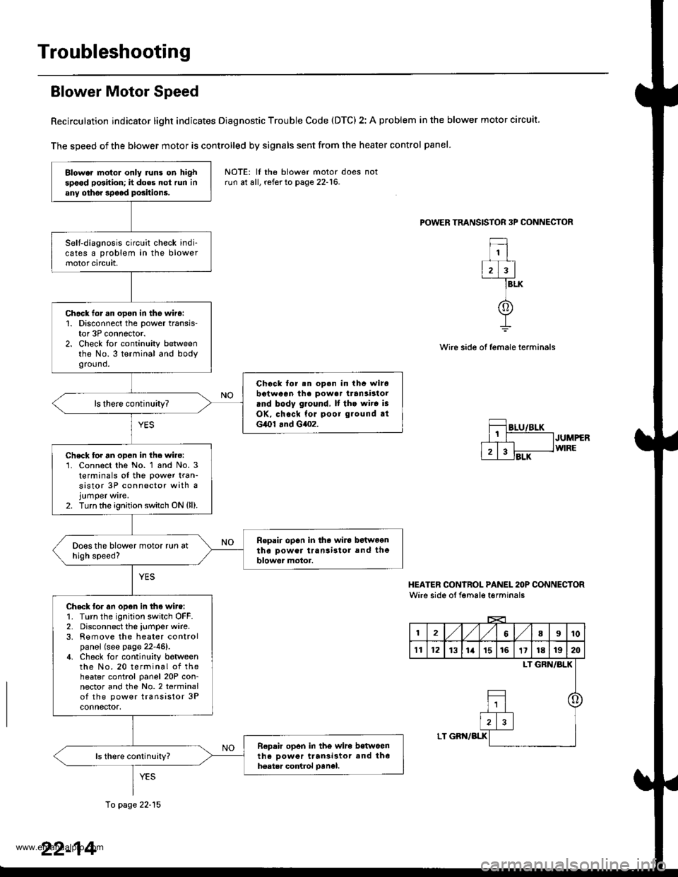
Troubleshooting
Blower Motor Speed
Recirculation indicator light indicates Diagnostic Trouble Code (DTC) 2: A problem in the blower motor circuit
The speed of the blower motor is controlled by signals sent from the heater control panel
POWER TRANSISTOR 3P CONNECTOR
1
2)3
f
BLK
Wire side of female terminals
JUMPERWIRE
HEATER CONIROL PANEL 2OP CONNECTORWire side oI fgmale t€rminals
12,/1,/68I10
't112131ia't51611181920
LI GRN/BLK
o
LT GBN/BLK
Blower motol only runs on highspood position; h does not run inany othe. speod positions.
Self-diagnosis circuit check indi-cates a problem in the blowermotor circuit,
Chack lor.n open in the wire:1. Disconnect the power transis-tor 3P connector.2. Check for continuity betweenthe No.3 terminal and bodygro(1nd.
Chock for.n op.n in thc wirobotween ihe powa. transistorrnd body ground, It tho wir. is
OK, check for poor ground atG,O1 .nd G4o2.
ls there continuity?
Chsck for an opon in the wire:'1. Connect the No. 1 and No. 3t€rminals of the power tran-sistor 3P connector with ajumper ware.2. Turn the ignition switch ON {ll).
Repair op6n in the wiro betwoontho Dower transi3tol and theblowor motor.
Check tor an open in tho wire:1. Turn the ignition switch OFF.2. Disconnect the iumper wire.3. Remove the heater controlpanel (see page 22-46).4. Check for continuity botweenthe No. 20 terminal of theheater control panel 20P con-nector and the No.2 terminalof the power transistor 3Pconnectof,
R€pair opon in tho wire betwoenth6 oowor ttan3i3tor and th6hoatar control oanel.
NOTE: lf the blower motor doesrun at all, refer to page 22-16.
10 page 22-15
22-14
www.emanualpro.com