diagnosis HONDA CR-V 1999 RD1-RD3 / 1.G User Guide
[x] Cancel search | Manufacturer: HONDA, Model Year: 1999, Model line: CR-V, Model: HONDA CR-V 1999 RD1-RD3 / 1.GPages: 1395, PDF Size: 35.62 MB
Page 612 of 1395
Electrical Troubleshooting ('98 - 00 Models)
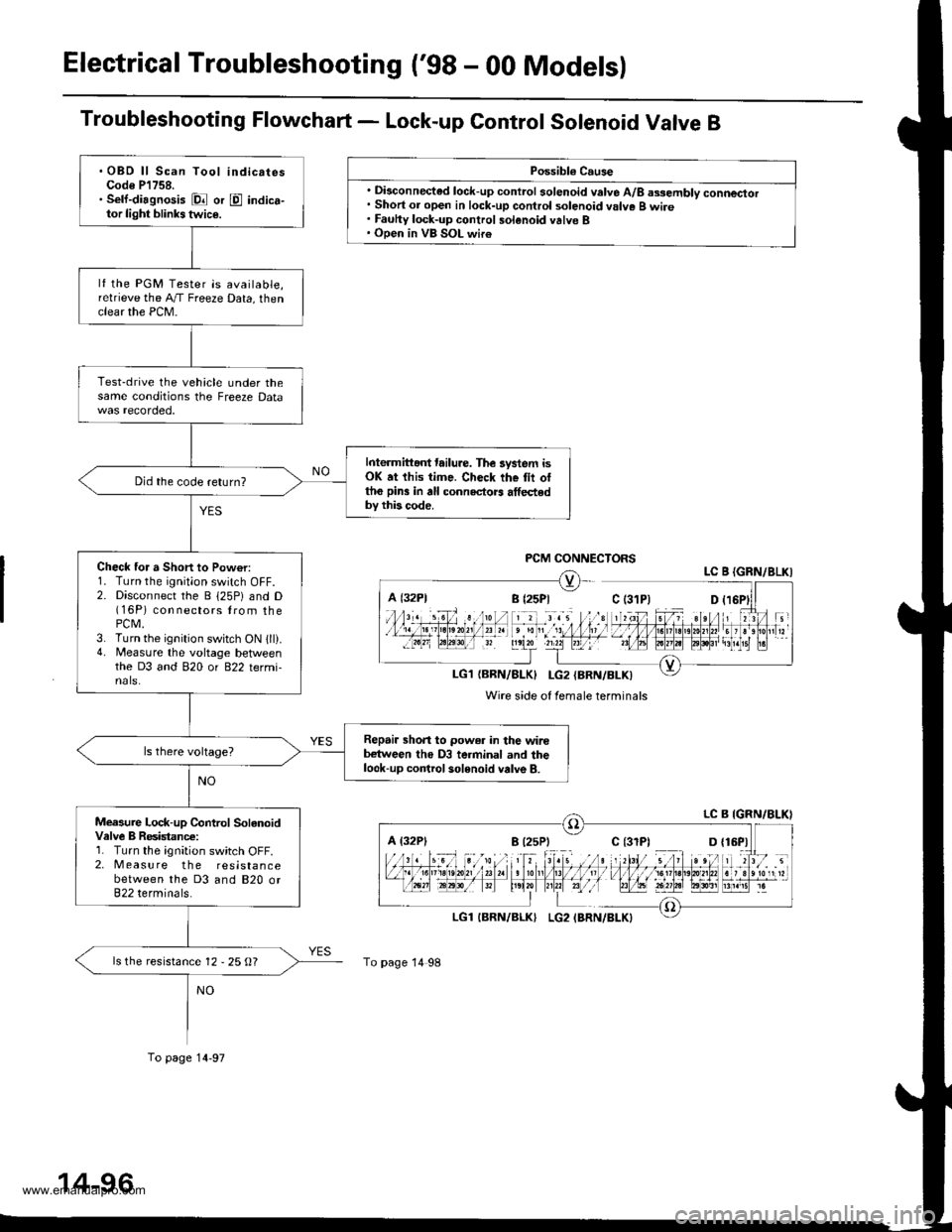
Troubleshooting Flowchart - Lock-up Control Sotenoid Valve B
Possibl€ Cause
. Disconnected lock-up control solenoid valve A/8 assembly connector. Short or open in lock-up control solenoid valve B wire. Fauhy lock-up control solenoid valve B. Open in VB SOL wir€
PCM CONNECTORSLC B {GRN/8LKI
LG1{BRN/BLK} I-G2{BRN/BLK)
Wire side of female terminals
A {32P1
To page 14 98
.OBD ll Scan Tool indicatesCode P'l758.. Sell-diagnosis Dl or E indica-tor light blinks twic€.
lf the PGM Tester is available,relrieve the A,/T Freeze Data, thenclear the PCM-
Test-drive the vehicle under thesame conditions the Freeze Data
Interm ittant tailure. The lystem isOK at this time. Check the tii ottho pin3 in all connectors athedby this code.
Did the code return?
Check for a Short to Pow€r:1. Turn the ignition switch OFF.2. Disconnect the B 125P) and D(16P) con nectors lrom thePCM.3. Turn the ignition switch ON 1ll).4. Measure the voltage betlveenthe D3 and 820 or 822 termi-nals.
Repair shon to power in the wirebetween tho D3 terminal and thelook-up control solenoid valve B.
Measure Lock-up Control SolanoidValve B Resistanc€:1. Turn the ignition switch OFF.2. Measure the resistancebetween the D3 and 820 or822 terminals.
ls the resistance 12 - 25 O?
To page 14-97
www.emanualpro.com
Page 619 of 1395
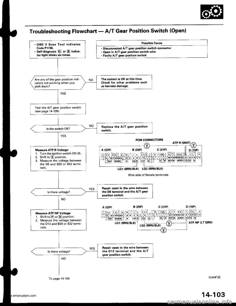
Troubleshooting Flowchart - A/T Gear Position Switch (Open)
Po$iblg Cause
. Dbconnected A/T gear position switch connoctor. Open in A/T gear po3ition switch wiro. Faulty A/T g€ar position switch
Wire side of female terminals
LGl {SRN/BLK)
{cont'd)
P,CM CONNECTORS
LGT(BNN/BLKI LG2IBRN/BLK)
A {32P)c l31P)
ATP NP (LT GRN}
. OBD ll Scan Tool indicatesCodo Pl706.. Self-diagnosis Fl or E indica-to. lighl blinks six times.
The system is OK.tthis time.Check for oth6r probl€ms suchas harne3s damage.
Are any ofthe gear position indicators not working when you
shift them?
Test the A/T gear position switch(see page 14-139).
Measure ATP R Vohago:1. Turn the ignition switch ON (ll).
2. Shitt to E position.
3. Measure ihe voltage betweenthe D6 and 820 ot 822 tetfiinals,
Repair open in tho wiro betwoenthe D6 terminal and the A/T gear
oosition switch.
Measure ATP NP Volt.g€:1. Shift to Elor E position.
2. Measure the voltage betweenthe D13 and 820 or 822 terminals,
Repair open in the wiro betweenth€ Dl3 terminal and th€ A/Tgesr posilion awitch.
To page 14-104
14-103
www.emanualpro.com
Page 622 of 1395
Electrical Troubleshooting ('98 - 00 Models)
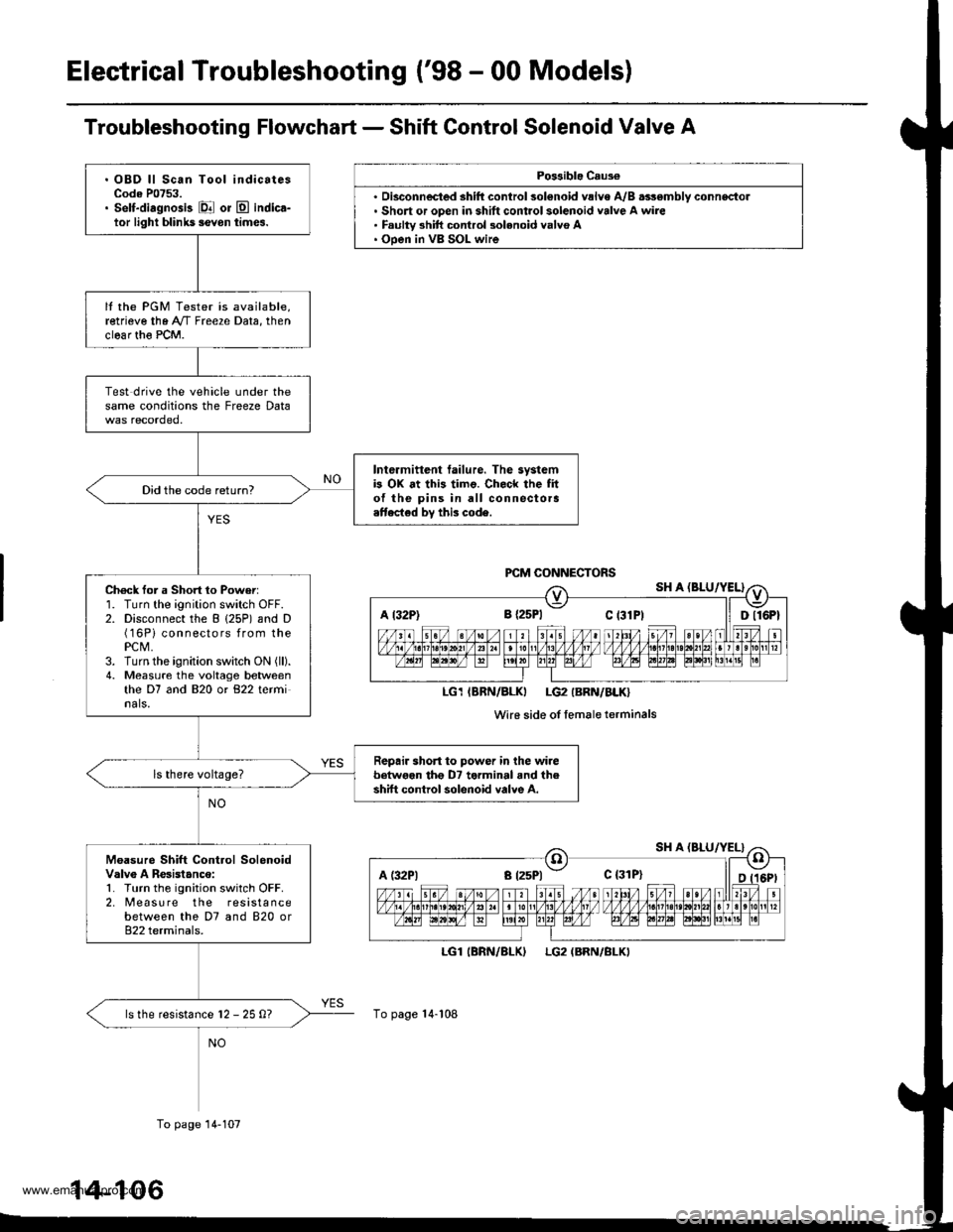
Troubleshooting Flowchart - Shift Control Solenoid Valve A
Po$ible Caus€
'. Short or open in shift control solenoid valve A wire. Faulty 3hift control 3olenoid valvo A. Ooen in VB SOL wire
LGl
To page 14-108
(BRN/BLKILG2 (BRN/BLKI
A t32P) 8 {2sPl Ct3lPt ll Dll6Pt
LG1IBRN/BLKI LG2IBRN/BLK}
Wi16 side of femaleterminals
A (:l2Pl a t25Pl - c {31P}
. OBD ll Scan Tool indicatesCode P0753.. Self-diagnosis El or E indica-tor light blihk5 ievon times.
It the PGM Tester is available,retrieve the A"/T Freeze Data, thenclear th€ PCM.
Test drive the vehicle under thesame conditions the Freeze Data
Intermittent tailure. The systemb OX at this timo. Check the fito{ the pins in all connectora.ttected by this code.
Did the code return?
Ch6ck for a Short 1o Power:1. Turn the ignition switch OFF.2. Disconnect the B (25P) and D(16Pi connectors from thePCM,3. Turn the ignition switch ON (ll).
4. Measure the voltage betweenthe D7 and 820 or 822 terminals.
Repair short to power in the wirebetwoen tho D7 terminal and theshift control solenoid valve A.
Moasure Shift Control SolenoidValv6 A Resistanco:1. Turn the ignition switch OFF.2. [reasu re the resistancebetween the D7 and 820 or822 terminals.
ls the resistance l2 - 25 0?
To page 14-107
14-106
www.emanualpro.com
Page 628 of 1395
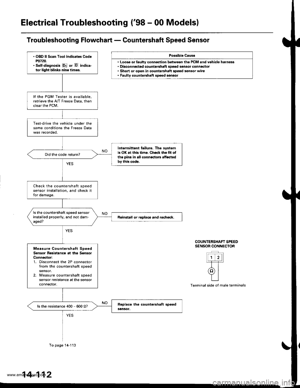
Electrical Troubleshooting ('98 - 00 Models)
Po$ibl€ Csuse
. Loo3€ or tauhy conn€ction batween the PCM and vehicle harness. Diaconnected countetshaft 3Deod sensor connectoa. Short or opon in countershalt spegd sensor wiro. Faulty countershatt spoed sensol
COUNTERSHAFT SPEEDS€NSOR CONNECIOR
ttt'l-T-T-
rolYILI
Terminal side of male terminals
. OgD ll Sc.n Tool indicat* Codem720.' selt-diagnosis E or E indica-tor light blinks nin6 time3.
It the PGM Tester is available,retrieve the A"/T Freeze Data, thenclear the PCM.
Test-drive the vehicle under thesame conditions the Freeze Data
Intormittent failuro. The systomis OK .t thb time. Check the Iit ofthe pins in rll connsctors .fLctodbv thi! code.
Check the countershaft speedsensor installation. and check itfor damage.
ls the countershaft speed sensorinstalled properly. and not dam-aged?Reinstall or replace and rechcck.
Measure Countershaft Sp6€dSonsoa R€sistsnc€ at the SenlorConnector:1. Disconnect the 2P connectorfrom the countershaft speed
2. Measure countershaft speedsensor resrstance at the sensorconnector.
ls the resistance 400 - 600 0?
To page 14-113
14-112
www.emanualpro.com
Page 633 of 1395
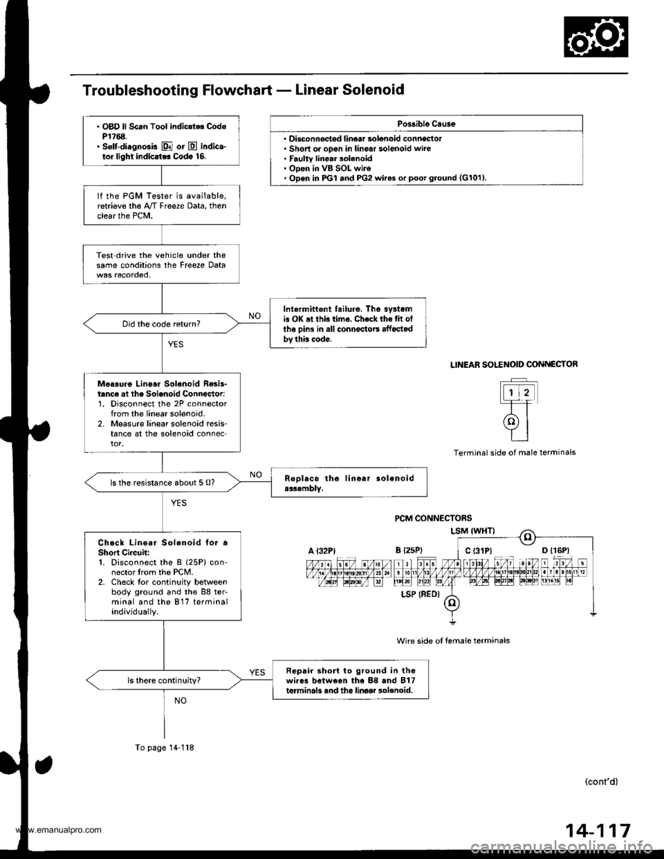
Po$ible Cau3e
' Disconnectsd linoar solenoid conneclol. Short or open in linear solenoid wire. Faulty linear 3olenoid. Open in VB SOL wire. Open in PGI and PG2 wires or poot g.ound {G101).
. OBD ll Scan Tool indic{t.. CodsP1768.. selt-diagnosis El or E indica-tor light indicrt.. Codo 16.
lf the PGM Tester is available.retrieve the A/T Freeze Data, thenclear the PCM.
Test drive the vehicle under thesame conditions the Freeze Data
Inlermittont tailure, The 3yrtomis OK at thb time. Check the tit otlhe oins in all connectoE affoctodby this code.
Did the code return?
Meaaure Linear Solenoid R€sis-tanc€ at the Solenoid Connector:1. Disconnect the 2P connectorfrom the linear solenoid-2. Measure linear solenoid resis-tance at the solenoid connector.
ls the resistance about 5 O?
Chock Lino.r Sol.noid to. aShort Circuh:1. Disconnect the B (25P) con-nector lrom the PCM.2. Check tor continuity betweenbody ground and the 88 ter-minal and the 817 terminalindividually.
Repair 3ho to ground in thewires belween the 88 rnd B17terminals and tho linaar 3olenoid.ls there continuity?
A l32PtB {2sP)
LSP (REDI
To page 14-118
SOLENOID COiINECTOR
t-rtt
(9l
tt
LINEAR
Terminal side ol male terminals
wire side oI temale terminals
(cont'd)
14-117
www.emanualpro.com
Page 637 of 1395
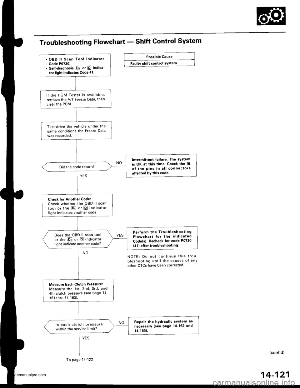
Troubleshooting Flowchart - Shift Control System
Possible Cause
Faultv shift control sYstem
NOTE: Do not continue thas trou
bleshooting until the causes of any
other DTCS have been corrected.
(cont'd)
14-121
. OBD ll Scan Tool indicates
Code P0730.. Self-diagnosis Jir or E indica-
tor light indicates Code 41.
lf the PGM Tester is available,
retrieve the AJ.I Freeze Data, then
clear the PCM.
Test-drive the vehicle under the
same conditions the Freeze Data
lntermittent failure. The system
is OK at this time. Ch€ck the fit
of the pins in all connectors
atfected by this code.
Did the code return?
Check for Another Code:
Check whether the OBD ll scan
tool or the l-Drl or E] indicator
light indicates another code.
Perlorm the TroubleshootingFlowchart for the indicaled
Codets). Recheck for code P0730
{411 6ft6r troubleshooting.
Does the OBD ll scan tool
or the Da or E indicatorlighl indicate another code?
Measure Each Clutch Pressure:
Measure the 1st, 2nd, 3rd, and
4th clutch Pressure (see Page 14
161 thru 14163).
Repair the hydraulic sYstem as
necessary (se€ page 14-162 and
14-163).
ls eac h clutch Pressurewithin the service limit?
To page 14-122
www.emanualpro.com
Page 669 of 1395
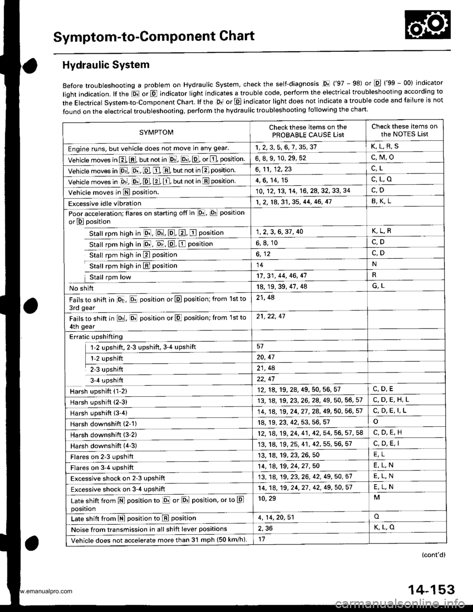
Symptom-to-Component Chart
Hydraulic System
Before troubleshooting a problem on Hydraulic system, check the self-diagnosis Dl ('97 - 98) or Lq ('99 - 00) indicator
light indication. lf the El or E indicator light indicates a trouble code, perform the electrical troubleshooting according to
the Electrical System-to-Component Chart. lf the Ol or E indicator light does not indicate a trouble code and failure is not
found on the electrical troubleshooting, perform the hydraulic troubleshooting following the chart.
SYMPTOMCheck these items on the
PROBABLE CAUSE List
Check these items on
the NOTES List
Engine runs, but vehicle does not move in any gear.1r2FAt?82?K,L.R,S
Vehicle moves in El. @, but not in lE. E, E, or E, position6, 8, 9, 10, 29, 52c,M,o
Vehicle moves in [D!. E, E. E, E, but not in E] position.al
Vehicle moves in .&1, E. E, E, E, but not in E position4,6, 14, 15c,L.o
Vehicle moves in E position.10 , 12, 13, '�l4, '16, 2A, 32, 33, 34
Excessive idle vibration1,2, 18,3'1,35, 44, 46, 41B,K,L
Poor acceleration; flares on starting off in E, Di position
or E position
Stall rpm hish in El, El, E, E, E Position
Stall rpm hiqh in E, E, E, E position
1,2,3,6,37, 40K,L,R
6, 8, 10C,D
Stall rpm high in E positionc,D
Stall rpm high in hl position14N
Stall rpm low17,31, 44, 46, 47R
No shift18, 19, 39, 47, 48G,L
Fails to shift in Pr, E position or E position; from 1st to
3rd gear
21, 48
Fails to shift in EJ, E position or E position; from 1st to
4th gear
21,22, 47
Erratic upshifting
fz upshlft. ,3 ripshlft, 3r. up+ilft57
ffi20, 47
il21, 4A
3-4 upshift22, 47
Harsh upshift ('l-2)12, 18, 19,2A,49, 50, 56, 57
Harsh upshift (2-3)13, 1A, 19,23,26,28, 49, 50, 56, 57C,D.E,H,L
Harsh upshift {3-4)14,1A, 19,24,27,28, 49, 50, 56. 57C, D, E, I,L
Harsh downshitt (2-1)18, 19,23, 42,53,56,51o
Harsh downshift (3-2)12, 18,19,24,41,42, 54. 56, 57, 58
Harsh downshift (4-3)13,'1A, 19, 25, 41, 42, 55, 56, 57C, D, E, I
Flares on 2-3 upshift13,1A,19,23,26,50FI
Flares on 3-4 upshift14, 1A, 19,24,27,50E,L,N
Excessive shock on 2-3 upshift13. '18, 19 , 23, 26, 42, 49 , 50, 51E.L.N
Excessive shock on 3-4 upshift14, 1A, 19,24,27 , 42, 49,50,51E,L,N
Late shift from N position to ld or Erl position. or to E
position
10, 29M
Late shift from E position to E position4, 14,20,51o
Noise from transmission in all shift lever positions2,36K,L.O
Vehicle does not accelerate more than 3l mph (50 km/h).11
(cont'd)
14-153
www.emanualpro.com
Page 803 of 1395
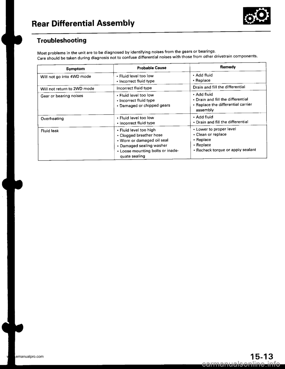
Rear Differential AssemblY
Troubleshooting
Most problems in the unit are to be diagnosed by identifying noises from the gears or bear'ngs'
care should be taken during diagnosis not to confuse differential noises with those from other drivetra'n components'
SymptomProbable CauseRemedy
Will not go into 4WD mode. Fluid level too low
. Incorrect fluid type
. Add fluid. Replace
Will not return to 2WD modeIncorrect fluid typeDrain and fill the differential
Gear or bearing noisesFluid level too low
Incorrect fluid type
Damaged or chipped gears
Add fluid
Drain and fill the differential
Replace the differential carrier
assemory
Overheating. Fluid leveltoo low
. Incorrect fluid type
. Add fluid. Drain and fill the differential
Fluid leakFluid level too high
Clogged breather hose
Worn or damaged oil seal
Damaged sealing washer
Loose mounting bolts or inade-
quate sealing
Lower to proper level
Clean or replace
Replace
Replace
Recheck torque or aPPIY sealant
15-13
www.emanualpro.com
Page 952 of 1395
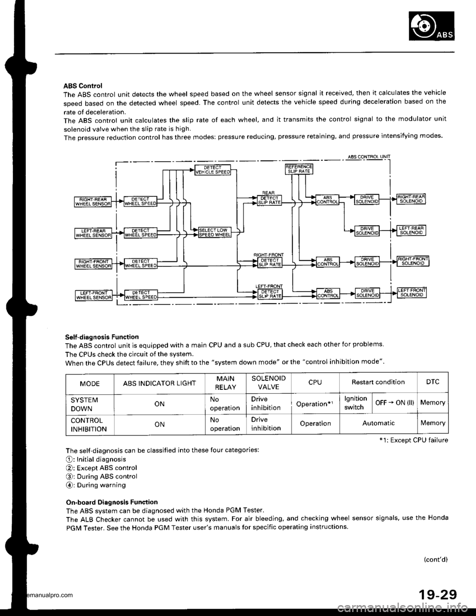
ABS Control
The ABS control unit detects the wheel speed based on the wheel sensor signal it received, then it calculates the vehicle
speed based on the detected wheel speed. The control unit detects the vehicle speed during deceleration based on the
rate of deceleration.
The ABS control unit calculates the slip rate of each wheel, and it transmits the control signal to the modulator unit
solenoid valve when the slip rate is high
The pressure reduction control has three modes: pressure reducing, pressure retaining, and pressure intensi{ying modes.
Self-diagnosis Function
The ABS control unit is equipped with a main cPU and a sub cPU, that check each other for problems.
The CPUs check the circuit of the system.
When the CPUS detect failure, they shift to the "system down mode" or the "control inhibition mode".
The self-diagnosis can be classitied into these four categories:
O: Initial diagnosis
O: Except ABS control
O; During ABS control
@: During warning
On-board Diagnosis Function
The ABS system can be diagnosed with the Honda PGM Tester.
The ALB Checker cannot be used with this system. For air bleeding. and checking wheel sensor signals, use the Honda
PGIM Tester. See the Honda PGM Tester user's manuals for specific operating instructions.
(cont'd)
19-29
ABS CONTROL I-INIT
MODEABSINDICATOR LIGHTMAIN
RE LAY
SOLENOID
VALVERestan conditionDTC
SYSTEM
DOWNONNo
operatron
Drive
inhibitionOperation*rlgnition
switchOFF - oN (ll)Memory
CONTROL
INHIBITIONONNo
operaton
Drive
inhibitionOperationAutomaticlVemory
*1: Except CPU failure
www.emanualpro.com
Page 959 of 1395
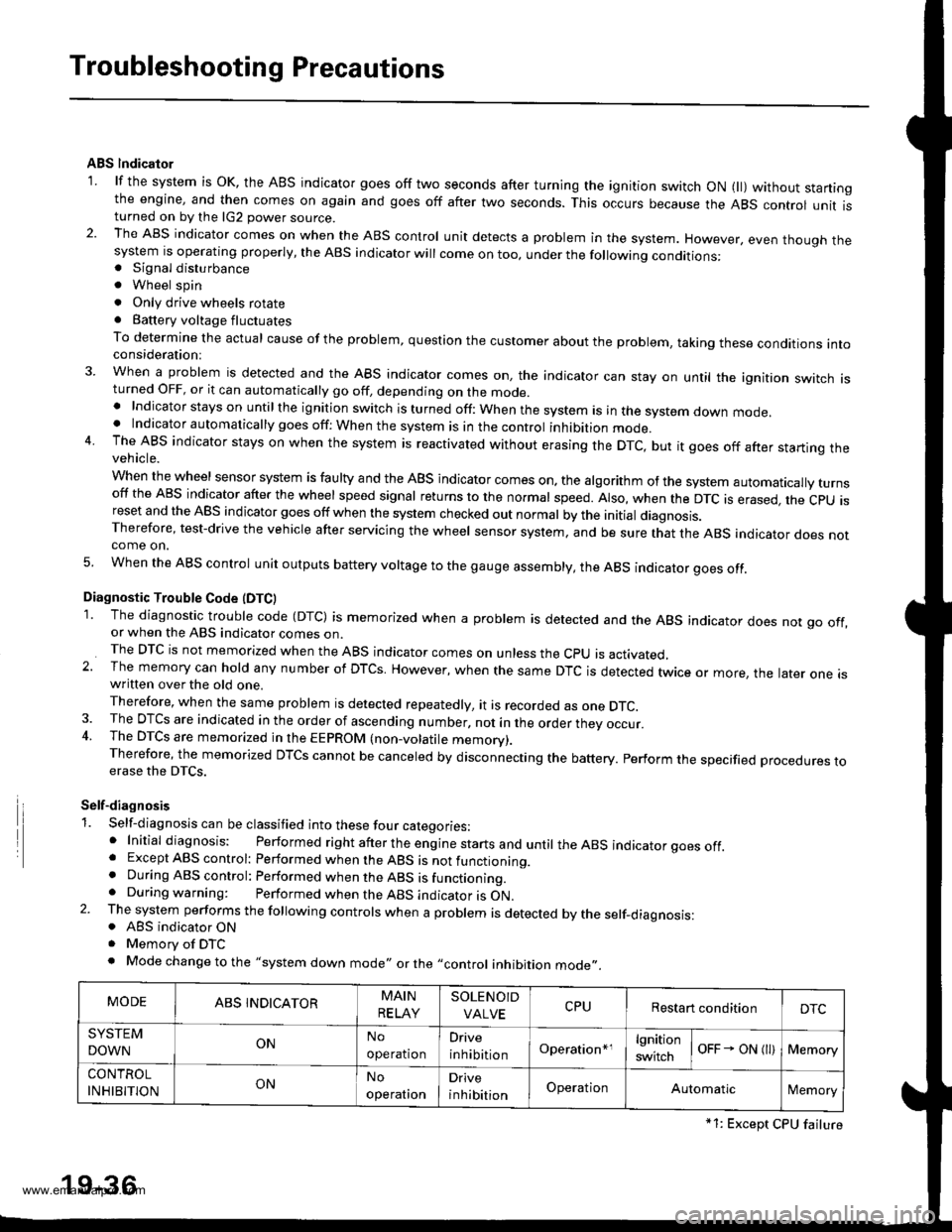
Troubleshooting Precautions
ABS lndicalor
1 lf the system is oK, the ABS indicator goes off two seconds after turning the ignition switch oN 1l) wathout staningthe engine, and then comes on again and goes off after two seconds. This occurs because the ABS control unit isturned on by the lG2 power source.2. The ABS indicator comes on when the ABS control unit detects a problem in the system. However, even thouoh thesystem is operating properly, the ABs indicator will come on too, under the following conditions:. Signal disturbance
. Wheel spin
. Only drive wheels rotate. Battery voltage fluctuates
To determine the actual cause of the problem, question the customer about the problem, taking these conditions intoconsideration:
3 When a problem is detected and the ABS indicator comes on, the indicator can stay on until the ignition switch isturned OFF, or it can automatically go off, depending on the mode.. Indicator stays on untilthe ignition switch is turned off: When the system is in the system down mode.. Indicator automatically goes off: When the system is in the control inhibition mode.4 The ABS indicator stays on when the system is reactivated without erasing the DTC, but it goes off after starting thevehicle.
When the wheel sensor system is faulty and the ABS indicator comes on. the algorithm of the system automatically turnsoff the ABS indicator after the wheel speed signal returns to the normal speed. Also, when the DTc is erased, the cpu isreset and the ABS indicator goes off when the system checked out normal by the initial diagnosis.Therefore, test-drive the vehicle after servicing the wheel sensor system. and be sure that the ABS indicator does notcome on.
5 When the ABS control unit outputs battery voltage to the gauge assembly, the ABS indicator ooes off.
Diagnostic Trouble Code (DTCI
1. The diagnostic trouble code (DTc) is memorized when a problem is detected and the ABS indicator does not go off,or when the ABS indicator comes on.The DTc is not memorized when the ABS indicator comes on unress the cpu is activated,2 The memory can hold any number of DTCs. However, when the same DTc is detected twice or more, the tater one iswritten over the old one.
Therefore, when the same problem is detected repeatedly, it is recorded as one DTC.3. The DTCs are indicated in the order of ascending number, not in the order they occur.4. The DTCS are memorized in the EEPROM (non-volatile memorv).Therefore, the memorized DTcs cannot be canceled by disconnecting the battery. perform the specified procedures toerase the DTCS.
Self-diagnosis
1. Self-diagnosis can be classified into these four categories:' Initial diagnosis: Performed right after the eng ine starts and untir theABS indicator goes off.. Except ABS control: Performed when the ABS is not functioning.. During ABS control: Performed when the ABS is functioning.. During warning: Performed when the ABS indicator is ON.2. The system performs the fo|owing contrors when a probrem is detected by the serf-diagnosis:. ABS indicator ON. Memorv of DTC. Mode changetothe "system down mode,, or the ,,control inhibition mode,,.
MODEABS INDICATORMAIN
RELAY
SOLENOID
VALVECPURestart conditionDTC
SYSTEM
DOWNONNo
operation
Drive
inhibitionOperation*rlgnition
switchoFF - ON l)Memory
CONTROL
INHIBITIONONNo
operal|on
Drive
inhibitionOperationAutomaticlMemory
*1: Except CPU failure
19-36
www.emanualpro.com