gear sensor HONDA CR-V 1999 RD1-RD3 / 1.G User Guide
[x] Cancel search | Manufacturer: HONDA, Model Year: 1999, Model line: CR-V, Model: HONDA CR-V 1999 RD1-RD3 / 1.GPages: 1395, PDF Size: 35.62 MB
Page 451 of 1395
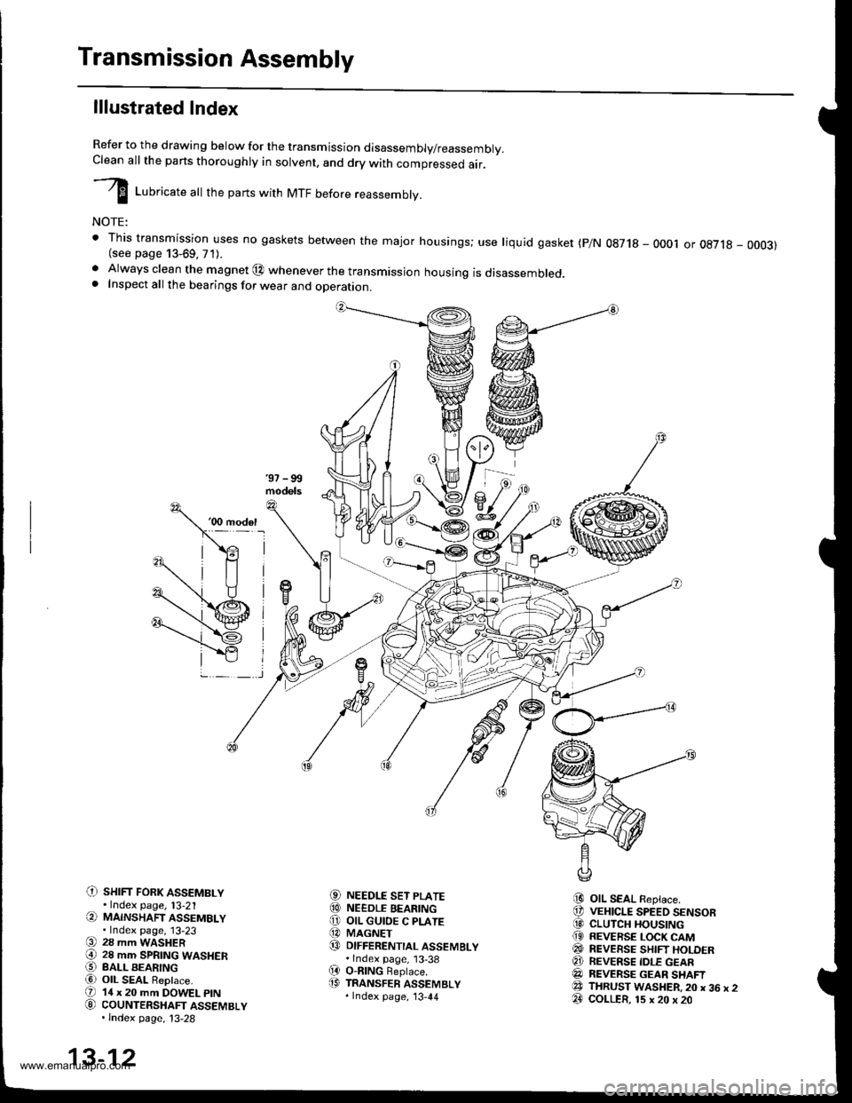
Transmission Assembly
lllustrated Index
Refer to the drawing below for the transmission disassembly/reassembly.Clean all the pans thoroughly in solvent, and drv with comoressed air.
I LuUri""r" utt the parts with MTF before reassembly.
NOTE:
t This transmission uses no gaskets between the major housings; use liquid gasket (p/N 0g718 - 0001 or oE7l8 - 0003)(see page 13-69, 71).. Always clean the magnet @ whenever the transmissjon housing is disassembled.. Inspect all the bearings for wear and operation.
C) sHrFr FoRK ASSEMBLY.Index page, l3-21(a MAINSHAFT ASSEMBLY.Index page, 13-23(9 28 mm WASHER€) 28 mm SPRTNG WASHERO BALL BEARINGa6) OIL SEAL ReDlace.(D 14 x 20 mm DOWEL ptN
G) couNTERSHAFT ASSEMBLY.lndex page, 13-28
NEEDLE SET PLATENEEDLE BEARINGOIL GUIOE C PLATEMAGNETDIFFERENTIAL ASSEMBLY.lndex page, 13-38O-nlNG Beplace.TRANSFER ASSEMBLY.Index page, '13,44
OIL SEAL Replace.VEHICLE SPEED SENSORCLUTCH HOUSINGREVERSE LOCK CAMREVEESE SHIFT HOLDERREVERSE IDLE GEARREVERSE GEAR SHAFTTHRUST WASHER,20 x 36 x 2COLLER, 15 x 20 x 20
aol
@o@@
(D
i9
@@@(9
@@@e3@
13-12
www.emanualpro.com
Page 517 of 1395

Automatic Transmission
Special Tools . 14'2OescriptionGeneral Operation . .... 14 3Power Flow . . .. '14_6
Electronic Control System .. .. . . .. .14_15Hydraulic Control .. 14 24Hydraulic Flow....-....... .. . .... .. .. . 14_29Lock'up Syslem .. .'t4'39Electrical SystemComponenl Locdlrons 14 45
PCM Circuil Dragram (A/T Control Svstem)'97 Model ....................... . . .. - . ... .14-46'98Model ................. . ... .. .. .1450'99 00Models.... . .... . . . 1452
PCM Terminal Voltage/Measuring ConditionsA"/T Control System-'97Model ...... ..14'48A,/T Control System -'98 00 Models . . .. . . 14 54
Troubleshooting Procedures .. ..... ... - 14_56Svmotom to comoonent CharlEiectr,cal Syslem -'97 Model . . 14 60Electrical System -'98 - OO Models . .. . . 14_62Electrical Troubleshooting ('97 Model)Troubleshooting Flowaharts .... ..... . .. . . 14_64
Electrical Troubleshooting ('98 - 00 Models)Troubleshootinq Flowclt"n" .... . ....- . .14-93ElectricalTroublesliooting('99 00Models)Troubleshootino FlowchartO/D OFF Indicator Light Does Not Come On 14 131
O/D OFF Indicator Liaht On ConstantlY . . . .1!-132O/D OFF Indicator Light Does Not Come OnEven Though O/D Switch ls Pressed . .... - 14_133
Lock up Control Solenoid Valve A,/B AssemblyTest....................-......... . .14-135Replacement . .ll_135Shifr ControlSolenoid Valve Ay'B Assembl,Test .............................. . .. 14-136
Replacement..............- . .14'136Linear Solenoid AssemblYTest.............................................. .. .... . 14_137Replacement .. . 14138Marnshaftlcountershafl Speed SensorsReplacement ...-... 14_138A/T Gear Position SwitchTest ..........................-... . .. 14-139ReplacementA/T Gear Positionlndicator.................. 14-140
Valve Eodynepair ............................... ..... . . .. - . .. ... 14 192
Assembly .................... .. 1{_193
Valve CapsDesciiption....-........................ .. ...... 14194
tnspeition ................... .. 14' 195
N4ain Valve BodyDisassembly/lnspection/Reassemblv - ...... .. 14_196
Secondarv Valve BodYDisassemblv4nspectron/ReassemblY .. . 14 198
Reoulator Valve Bodvbisassembtv,lnspiction/Reassemblv . 14199
Servo EodvDisassembly/lnspection/Reassembly ... ....14'200
Lock'uo Valve BodYDis;ssembly/lnspection/Reassembly .... . 14_201
MainshaftDisassembly/lnspection/Reassembly .. .. .. ..14'202
Inspection ....-.............. ..11_203
Sealing RingsReilaceient ...... ..... . 14'204
CountershaftDisassembly/lnspection/Reassembly .. . . . . . 11-205
Disassembly/Reassemb|y . . ........ ...... . .. 14_206Inspedron ................ . .... . 14 207
One wav ClutchDisassembly/lnspection/ReassemblY ... 11_209
Sub-shaftDisassembly/lnspection/Reassembly ... . .. . 14-210
oisassembly/Re6ssembly . . ... .-...... . . ..14-211
Sub-shaft BearingsReplacement .......14'212
Clutchllfustrated Index .......... . . .14-213
Disassembly .... .. .....14-216Reassembfy .... . .. .. . 14'218
Differentialllfustrated Index " 14-222Backlash Inspection . .... . .14'223
Bearing Repiacement .. 11-223
Differe-ntial Carrier Replacement .. .. . . . .. ..11-2?4
OifSeal Replacement. . .. 14'225
Side Clearance lnspection . . - .. ... . - ...... . .. 11'226
Transmission Housing BearingsMainshaJVCountershaft EearingsRepfacement .......14221Sub'siralt Eearing Replacement . . . . . . . . . ..11'224
Toroue Converter Housing BearingsMainshattEearing/OilSe6lReplacement . .. l4229
Countershaft Bea;ing Replacement.. .... .. ..14-230
Input Test - '97 - 98 ModelsInput Test '99 - 00 Models
Symptom to-Component ChartHydraulic System ...............
Checking
Removal ...,lllustrated Index (4WD)
Interlock SystemInterlock ControlUnit lnputTest. -..... -.. .... . - 14 144* Key Interlock Solenoid Test .- .. . . . - . . . ..... 14_146* Shift Lock Solenoid Test ..............-.-. . .. . ... .... 14 147*Shift LockSolenoidReplacement...... .. . .. .. 14 148* park pin Switch Test ......... 14 119' Park Pin Switch Replacement- '97 - 98 Models ....... 14-150* Park Pin Swirch/Over Drive (O/Di SwitchReplacemenl '99-00Models . .. 14_151over-Drive (O/D) Switch {'99 00 [4odels]Test........_..................... .......14-152Hydr.ulic System
..............._............... t4 142.................................. 14-143
Control Lever AssemblyR6placement ......,.,Reverse ldler Gear
lllustrated lndex
.......... 14-230
14 231
11-231
1nsta1|ation ..................Park StopInspeclion/AdjustmenlTransfer AssemblY.......14.232
RoadTest.............-.... ........ .StallSpeedTest ....._........................ ....... 14-159Fluid Level......_................... 14'160
Disessembly .................... 14-235Transfer Drive Gear BearingReplacementTrans{er Driven Gesf Shaft BearingReplacementTransfer Housing Roller BearingReplacementTransfer Cov€r A Bearing Outer RaceReplacementTransfer Housing Bearing Outer RaceReplacement ......-..,,,,,.....ReassemblvTransmassaonBeassembly ... -.. .... .14 250
Torque Converier/Drive Plate . .-. .... .. . ... .....14_258
Transmissionlnstatlation .................. ....... 14'259
Cooler Flushing . . ......11-261ATF Cooler HosesConnection.................. ....... 14-266I Shift LeverRemoval/lnstallation . .. 14'261
Disassemblv/Reassemblv - '97 - 98 Models . . 14_264
Disassembli/Reassemblv -'99 - 00 Models . 14-269
Over'Orive (O/D) Switch WireClearanceAdjustment. - ... . . . .. .. . 14'270
Detent Spring Replscement . . -.. ... .14'271*Shift CableAdiustment ....... 14'272
Repfacement.............. . 11'273
14 15711-237
11-237
14-238
$-234
11-23914-240
Transmigrion
Inspeclron ....., ...........Transfer AssemblyRemova1,.,,,..............,lnstallalion ........... .. ...Transmission
14 164
14-16514,167
14-169
End Cover/Transmissio . 14'174Transmission Housing .... ... .. . . .... .. 14-176Torque Converter Housingly'alve Body.. - ... -. 14 178
lllustrated lndex (2WD)End Cover/Transmissio ....... 14 180Transmission Housing . . ... . .. .... ... 14'182Torque Convener Housing/r'alve Body ......- 14-184
End CovefRemovat ...................... ....... 14'186Transmission HousingRemoval ...................... .. 14_188Torque Convener HousingA/alve BodYRemovat ................-..... .-..... 14-190
www.emanualpro.com
Page 519 of 1395

Description
General Operation
The Automatic transmission is a 3-element torque converter and triple-shaft electronically controlled unit which provides 4
speeds forward and 1 reverse speed The unit is positioned in line with the engine'
There are two tvoes of automatic transmission on CR-V; the four-wheel drive (4WD) model ('97 - 00)' and the front-wheel
drive (2WD) model ('98 - 00).
Toroue Converter, G€ars, and Clutches
The torque converter consists of a pump. turbine. and stator assembly in a single unit. The torque converter is connected to
the engine crankshatt. These parts turn together as a unit as the engine turns. Around the outside of the torque converter is
a ring gear which meshes with the starter pinion when the engine is started. The torque converter assembly serves as a fly-
wheel while transmitting power to the transmission mainshaft.
The transmission has three parallel shafts: the mainshaft. the countershaft, and the sub-shaft. The mainshaft is in line with
the engine crankshaft. The mainshaft includes the 1st, 2nd. and 4th clutches, and gears lor 3rd,2nd,4th. reverse and 1st
(3rd gear is integral with the mainshaft, while reverse gear is integral with the 4th gear). The countershaft includes the 3rd
clutch and gears for 3rd,2nd, 4th, reverse, 1st, and park. Reverse and 4th gears can be locked to the countershaft at its cen-
ter, providing 4th gear or reverse, depending on which way the selector is moved. The sub-shaft includes the lst-hold
clutch and gears for lst and 4th.
The gears on the mainshaft are in constant mesh with those on the countershaft and sub-shaft. When certain combinations
of gears are engaged by the ctutches, power is transmitted from the mainshaft to the countershaft to provide E, D!, tr, tr,
and E position ('97 - 98 models). and E. E, E, and E position ('99 - 00 models)'
Electlonic Control
The electronic controt system consists of the Powenrain Control Module (PCM), sensors, a linear solenoid, and four
solenoid valves. Shifting and lock-up are electronically controlled for comfortable driving under all conditions. The PCM is
located below the dashboard, under the kick panel on the passenger's side.
Hydraulic Control
The valve bodies include the main valve body, the secondary valve body, the regulator valve body, the servo body, and
the lock up valve body. They are bolted to the torque converter housing. The main valve body contains the manual valve,
the 1-2 shift valve, the 2nd orifice control valve. the CPB {Clutch Pressure Back-up) valve, the modulator valve, the servo
control valve. the relief valve, and ATF pump gears. The secondary valve body contains the 2-3 shift valve, the 3-4 shift
valve, the 3,4 orifice control valve. the 4th exhaust valve and the CPC (Clutch Pressure Control) valve. The regulator valve
bodv contains the pressure regulator valve, the torque converter check valve, the cooler relief valve, and the lock-up con-
trol valve. The servo body contains the servo valve which is integrated with the reverse shift tork, and the accumulators
The lock-up valve body contains the lock-up shift valve and the lock-up timing valve. The linear solenoid and the shift con-
trol solenoid valve Ay'B are bolted to the outside of the transmission housing, and the lock-up control solenoid valve Ay'B is
bolted to the outside of the torque converter housing. Fluid trom the regulator passes through the manual valve to the
various control valves. The clutches receive fluid from their respective feed pipes or internal hydraulic circuit
ShiftControl Mechanism
input from various sensors located throughout the vehicle determines which shift control solenoid valve the PCM will acti-
vate. Activating a shift control solenoid valve changes modulator pressure, causing a shift valve to move. This pressurizes
a line to one of the clutches. engaging that clutch and its corresponding gear. The shift control solenoid valves A and B are
controlled by the PCM.
Lock-up Mechanism
tn E! position (,97 - 98 modets) and in E position ('99 - O0 models), in 3rd and 4th, and in Del position in 3rd ('97 - 98
models) and in El position with Over,Drive (O/D) is OFF (by pressing rhe O/D switchl in 3rd ('99 - 00 models), pressurized
fluid is drained from the back of the torque converter through a fluid passage, causing the lock-up piston to be held
against the torque converter cover, As this takes place, the mainshaft rotates at the same speed as the engine crankshaft.
Together with hydraulic control, the PcM optimizes the timing of the lock-up mechanism The lock-up valves control the
range of lock-up according to lock-up control solenoid valves A and B, and the linear solenoid. When lock-up control
solenoid valves A and B activate, the modulator pressure changes. The lock-up control solenoid valves A and B and the
linear solenoid are controlled by the PCM.
{cont'd)
14-3
www.emanualpro.com
Page 533 of 1395
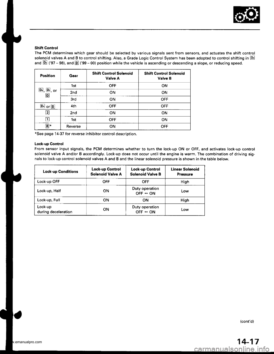
Shift Control
The PCM determines which gear should be selected by various signals sent from sensors, and actuates the shift control
solenoid valves A and B to control shifting. Also. a Grade Logic Control System has been adopted to control shifting in E
anO E ('gZ - gg), and E ('99 - 00) position while the vehicle is ascending or descending a slope, or reducing speeo.
PositionGearShift Control Solenoid
Valve A
Shift Control Solonoid
Valve B
E, E, Or
E
'I stOFFON
2ndONON
3rdONOFF
E orE4thOFFOFF
a2ndONON
tr1stOFFON
E-ReverseONOFF
*See page 14-37 for reverse inhibitor control description.
Lock-up Control
From sensor input signals, the PCM determines whether to turn the lock-up ON or OFF, and activates lock-up control
solenoid valve A and/or B accordingly. Lock-up does not occur until the engine is warm. The combination of driving sig-
nals to lock-up control solenoid valves A and B and the linear solenoid pressure is shown in the table below.
Lock-up ConditionsLock-up Control
Solonoid Valve A
Lock-up Control
Solenoid Valve B
Linear Solenoid
Pressuro
LOCK-Up \JrrOFFOFFHigh
Lock-up, HalfONDuty operation
OFF - ON
Lock-up, FullONONHish
Lock-up
during decelerationONDuty operation
OFF - ONLow
(cont'd)
14-17
www.emanualpro.com
Page 561 of 1395
![HONDA CR-V 1999 RD1-RD3 / 1.G User Guide
Component Locations
ASSEMBLY
POWERTRAIN CONTROLMODULE {PCMI
COUNTERSHAFTSPEED SENSOR
AUTOMAIIC TRANSAXI.E(A/T} GEAR POSITIONswtTcH
\
CONTBOL UN]T
SHIFT CONTROLSOLEM)ID VALVEASSEMBLY
SPEED SCNSOR
14-4 HONDA CR-V 1999 RD1-RD3 / 1.G User Guide
Component Locations
ASSEMBLY
POWERTRAIN CONTROLMODULE {PCMI
COUNTERSHAFTSPEED SENSOR
AUTOMAIIC TRANSAXI.E(A/T} GEAR POSITIONswtTcH
\
CONTBOL UN]T
SHIFT CONTROLSOLEM)ID VALVEASSEMBLY
SPEED SCNSOR
14-4](/img/13/5778/w960_5778-560.png)
Component Locations
ASSEMBLY
POWERTRAIN CONTROLMODULE {PCMI
COUNTERSHAFTSPEED SENSOR
AUTOMAIIC TRANSAXI.E(A/T} GEAR POSITIONswtTcH
\
CONTBOL UN]T
SHIFT CONTROLSOLEM)ID VALVEASSEMBLY
SPEED SCNSOR
14-45
www.emanualpro.com
Page 565 of 1395

PCM CONNECTOR B (25P) lcont'd)
PCM CONNECTOR C {31PI
PCM CONNECTOR D II6PI
Terminal NumbelSignalDescriptionMeasuring Conditions/Terminal voltage
811SHBShift control solenoid valve B
control
In E, E position, in 1st and 2nd gear in -q,
Er position: Battery voltage
In B position, in 3rd gear in qd, q:l,in atn
gear in D. position: 0 V
812ILUlnterlock controlWhen ignition switch is ON (ll), brake pedal
deDressed and accelerator oedal released:0 V
B13D4 INDD4 Indicator light controlWhen ignition switch is first turned ON (ll): 6 V
or more for tlvo seconds
In lDll position: 6V or more
814NMSGMainshaft speed sensor ground
815NMMainshaft speed sensor signal
InpuI
Depending on engine speed: Pulsing signal
When engine is stopped: 0 V
816ATP RAy'T gear position switch Eposition signal input
In E position; OV
In other than E position: Battery voltage
817ATP 2Ay'T gear position switch E posi-
tion signal input
InEposition:0V
In other than E position: Battery voltage
B18ATP 1A/T gear position switch El posi-
tion signal input
InEposition:0V
In other than E position: Battery voltage
819 to 821Not used
B�22NCSGCountershaft speed sensor ground
NCCountershaft speed sensor signal
Inpur
Depending on vehicle speed: Pulsing signal
when vehicle is stooped: 0 V
824ATP D4A/T gear position switch iql posi-
tion signal input
In E position: 0V
In other than lgal position: Baftery voltage
825ATP NPAy'T gear position switch E and
N position signals input
In E and E positions: 0V
In otherthan @ and ffi positions:5 V
Terminal NumberSignalDescriptionMeasuring Conditions/Terminal Voltage
SCSService check signalWith ignition switch ON (ll) and service check
connector open: 5 V
With ignition switch ON (ll) and service check
connector connected with special tool: 0 V
c10VBUBack-up power system(under-hood Fuse 47)
Always battery voltage
Terminal NumberSignalDescriptionMeasuring Conditions/Terminal Voltage
STOP SWBrake switch signal inputBrake pedal pressedr Battery voltage
Brake pedal released: 0 V
14-49
www.emanualpro.com
Page 571 of 1395
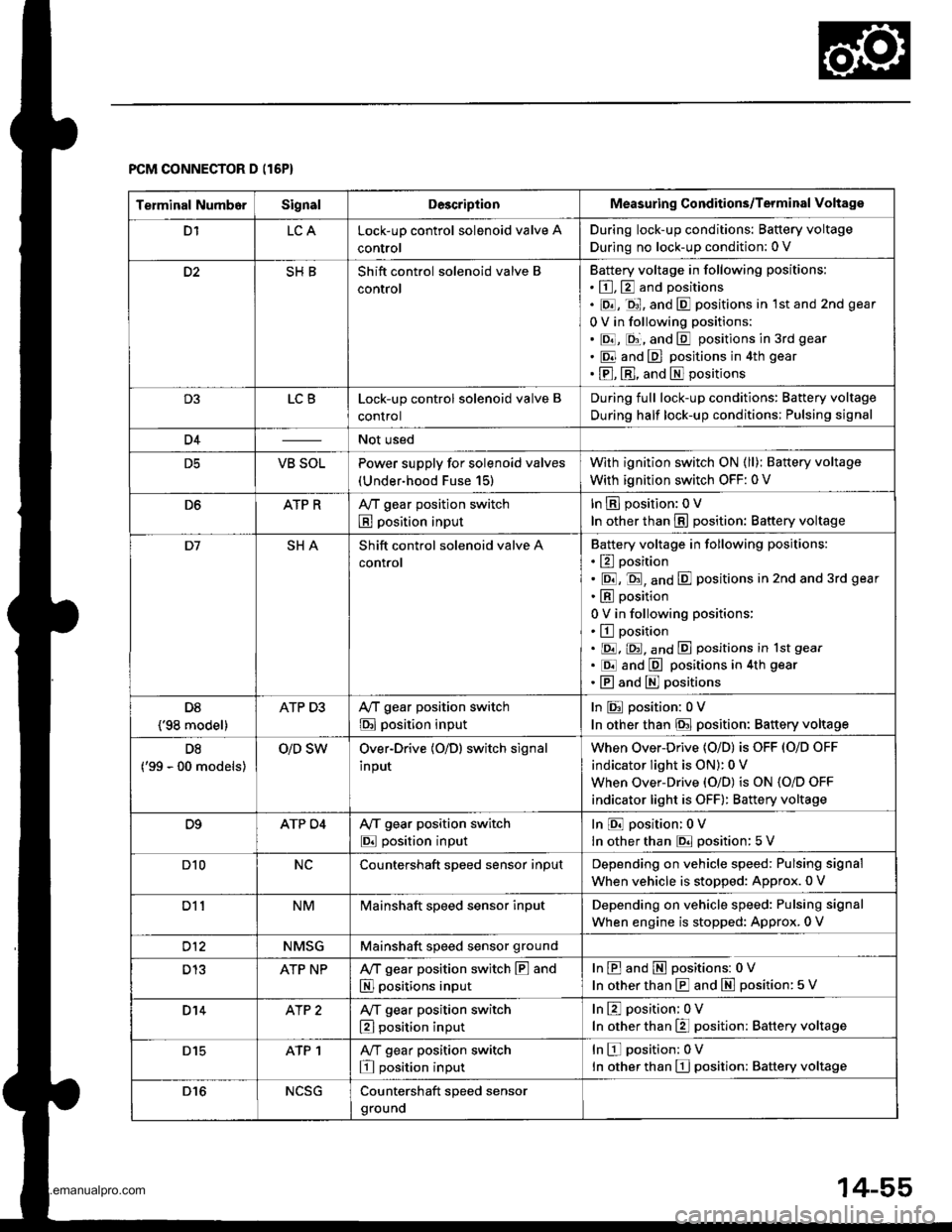
Terminal NumborSignalDescriptionMeasuring Conditions/Terminal Voltage
D1LCALock-up control solenoid valve A
control
During lock-up conditions: Baftery voltage
During no lock-up condition: 0 V
D2SHBShift control solenoid valve B
control
Battery voltage in following positions:
. E, E and positions
. E, -ql, and E positions in lst and 2nd gear
0 V in following positions:
. E, E;, and E positions in 3rd gear
. E and E positions in 4th gear
. E, El, and El positions
D3LCBLock-up control solenoid valve B
control
During full lock-up conditions: Battery voltage
During half lock-up conditions; Pulsing signal
D4Not used
D5VB SOLPower supply for solenoid valves
(Under-hood Fuse 15)
With ignition switch ON (ll); Battery voltage
With ignition switch OFF: 0 V
D6ATP RAy'T gear position switch
B position input
In E position: OV
In other than E position: Baftery voltage
D7SHAShift control solenoid valve A
control
Battery voltage in following positions:
. E position
. E, E, and E positions in 2nd and 3rd gear
. E position
0 V in following positions:
. E position. E. E, and E positions in lst gear
. Erl and E positions in 4th gear
.EandEpositions
D8
{'98 model}
ATP D3Ay'T gear position switch
E position input
In E position: 0V
In other than E position: Baftery voltage
D8
('99 - 00 models)
O/D SWOver-Drive (O/D) switch signal
input
When Over-Drive {O/D) is OFF (O/D OFF
indicator light is ON): 0 V
When Over-Drive {O/D) is ON {O/D OFF
indicator light is oFF): Battery voltage
D9ATP D4A/f gear position switch
E position input
In E position: 0V
In other than E position: 5 V
D10NCCountershaft sDeed sensor inoutDepending on vehicle speed: Pulsing signal
when vehicle is stopped: Approx.0 V
Dl1NMMainshaft speed sensor inputDepending on vehicle speed: Pulsing signal
When engine is stopped: Approx. 0 V
D12NMSGMainshaft speed sensor ground
D13ATP NPA,/T gear position switch E and
El positions input
InEandEpositions: 0V
In other than E and m position: 5 V
D14AlP 2A/T gear position switch
El position input
InE position; 0V
In other than E position: Battery voltage
D15ATP 1A,/T gear position switch
E position input
InEposition:0V
ln other than El position: Battery voltage
D16NCSGCountershaft speed sensor
grouno
PCM CONNECTOR D (16P)
14-55
www.emanualpro.com
Page 576 of 1395
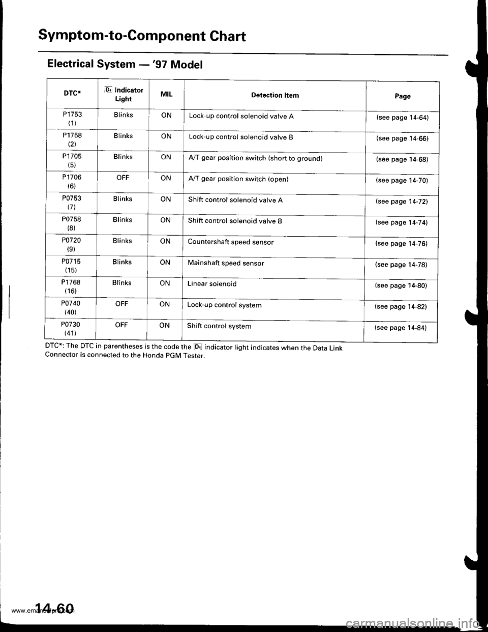
Symptom-to-Component Chart
Electrical System -'97 Model
DTC*: The DTc in parentheses is the code the loa indicator right indicates when the Data LinkConnector is connected to the Honda pGM Tester.
DTC*E Indicatol
LightMILDetection ltemPage
P 1753
(1)BlinksONLock up control solenoid valve A(see page 14-64)
P1758
\21
B linksONLock-up control solenoid valve B(see page 14-66)
P 1705
(5)BlinksONA,/T gear position switch (short to ground)(see page 14-68)
P1706
(6)OFFONA,/T gear position switch {open)(see page 14-70)
P0753
\11
B linksONShift control solenoid valve A(see page 14-72)
P0758
(8)BlinksONShift control solenoid valve B(see page 14-74)
P0720
(9)BlinksONCountershaft speed sensor{see page 14-76)
P0715
(15)B linksONMainshaft speed sensor(see page l4-78)
P17 68( 16)
BlinksONLinear solenoid(see page 14-80)
P0740
{40)
OFFONLock-up control system(see page 14-82)
P0730
(41)OFFONShift control system(see page 14-84)
14-60
www.emanualpro.com
Page 578 of 1395
Symptom-to-Component Chart
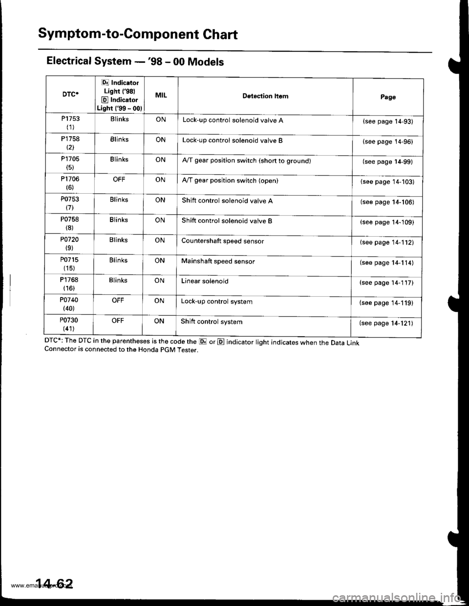
Electrical System -'98 - 00 Models
DTC*; The DTC in the parentheses is the code the E or E indicator light indicates when the Data LinkConnector is connected to the Honda pGM Tester.
DTC*
Et Indicatol
Lighr (98)
E Indicator
Light ('99 - 00)
MILDetestion ltomPage
P1753
(1)BlinksONLock-up control solenoid valve A{see page 14-93)
P1758
(21BlinksONLock-up control solenoid valve B(see page 14-96)
P1705(5)BlinksONA,/T gear position switch (shon to grounol(see page 14-99)
P1706(6)OFFONA,/T gear position switch (open)(see page 14-103)
P0753
(71Blin ksONShift control solenoid valve A(see page 14-106)
P0758
(8)BlinksONShift control solenoid valve B(see page 14-109)
P0720
(9)BlinksONCountershaft speed sensor{see page 14-112)
P0715
{15)
BlinksONMainshaft speed sensor(see page 14-114)
P1768
(16)BlinksONLinear solenoid(see page 14-117)
POl 40(40)OFFONLock-up control system(see page 14-119)
P0730
(41)OFFONShift control system(see page 14-121)
14-62
www.emanualpro.com
Page 661 of 1395
1?
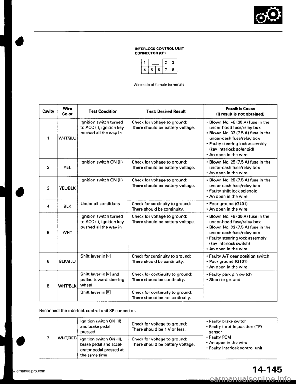
4678
CavityWire
ColorTest CondhionTost: Desired RosultPossible Cause(lf result is not obtainedl
1WHT/BLU
lgnition switch turned
to ACC (l), ignition key
pushed all the way in
Check for voltage to ground:
There should be battery voltage.
Blown No. 48 {30 A} fuse in the
under-hood fuse/relay box
Blown No.33 (7.5 A) fuse in the
under-dash fuse/relay box
Faulty steering lock assembly
{key interlock solenoid)
An open in the wire
YEL
lgnition switch ON (ll)Check for voltage to ground:
There should be battery voltage.
Blown No.25 (7.5 A) fuse in the
under-dash fuse/relay box
An open in the wire
YEUBLK
lgnition switch ON (ll)Check for voltage to ground:
There should be baftery voltage.
Blown No. 25 (7.5 A) fuse in the
under-dash fuse/relay box
Faulty shift lock solenoid
An open in the wire
4BLKUnder all conditionsCheck for continuity to ground:
There should be continuity.
. Poor ground (G401)
. An open in the wire
5WHT
lgnition switch turned
to ACC (l), ignition key
pushed all the way in
Check for voltage to ground:
There should be battery voltage.
Blown No.48 (30 A) fuse in the
under-hood fuse/relay box
Blown No. 33 (7.5 A) fuse in the
under-dash fuse/relay box
Faulty steering lock assembly(key interlock switch)
An open in the wire
BLI(BLU
Shift lever in ECheck for continuity to ground:
There should be continuity,
Faulty Ay'T gear position switch
Poor ground (G101)
An open in the wire
8WHT/BLK
Shift lever in @ and
pulled toward steering
wneel
Check for continuity to ground:
There should be continuity.
Faulty park pin switch
Shon to ground
Shift lever in ECheck for continuity to ground:
There should be no continuity.
Wire side of female terminals
Reconnect the interlock control unit 8P connector.
14-145
7WHT/RED
lgnition switch ON (ll)
and brake pedal
presseo
Check for voltage to ground:
There should be 1 V or less.
Faulty brake switch
Faulty throttle position (TP)
sensor
Faulty PCM
An open in the wire
Faulty interlock control unit
lgnition switch ON (lll,
brake pedal and accel-
erator pedal pressed at
the same time
Check for voltage to ground:
There should be baftery voltage,
www.emanualpro.com