oil HONDA CR-V 1999 RD1-RD3 / 1.G User Guide
[x] Cancel search | Manufacturer: HONDA, Model Year: 1999, Model line: CR-V, Model: HONDA CR-V 1999 RD1-RD3 / 1.GPages: 1395, PDF Size: 35.62 MB
Page 51 of 1395
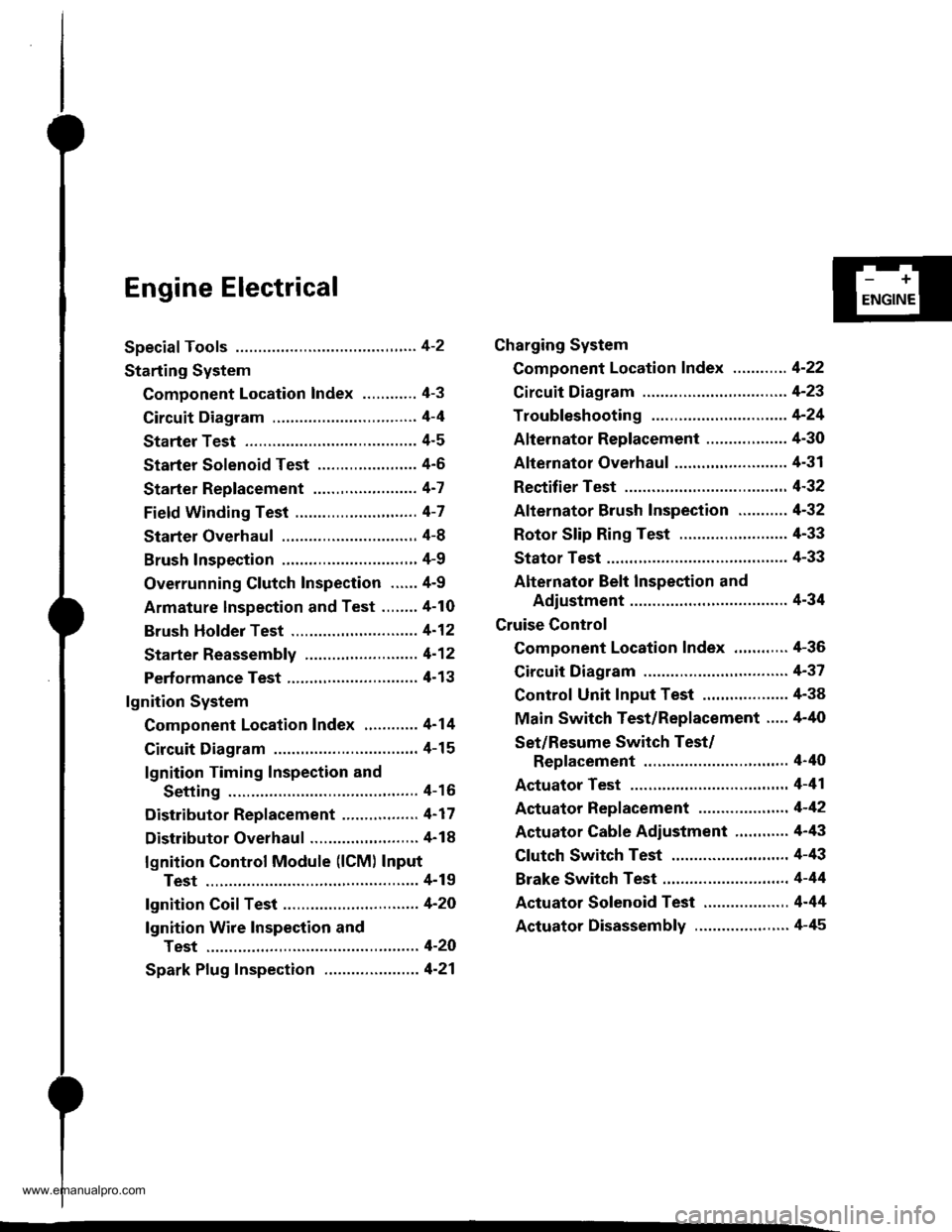
Engine Electrical
Speciaf Tools ............. 4-2
Starting System
Component Location Index ............ 4-3
Circuit Diagram ................................ 4-4
Starter Test ........... 4-5
Starter Solenoid Test ...................... 4'5
Starter Replacement ....................... 4-7
Field Winding Test ........................... 4-7
Starter Overhaul ............................,. 4-8
Brush Inspection ...........................,., 4-9
Overrunning Glutch Inspection ...... 4-9
Armature lnspection and Test ........4-10
Brush Holder Test ............................ 4-12
Starter Reassemb|y ......................... 4-1 2
Perf ormance Test ............................. 4- 1 3
lgnition System
Component Location Index ............ 4-14
Circuit Diagram ................................ 4-15
lgnition Timing Inspection and
Setting .......................................... 4-16
Distributor Replacement ........,........ 4-17
Distributor Overhaul .............,,......... 4-18
lgnition Control Module (lCM) Input
Test ..............................,................ 4-19
fgnition Coil Test .............................. 4-2O
lgnition Wire Inspection and
Test ............................................... 4-20
Spark Plug Inspection ..................... 4-21
-+
ENGINE
Charging System
Component Location Index ............ 4-22
Circuit Diagram ....................,........... 4-23
Troubleshooting .............................. 4-24
Alternator Replacement ..........,....... 4-30
Alternator Overhaul .......,,................ 4-31
Rectifier Test .........4-32
Alternator Brush Inspection ........... 4-32
Rotor Slip Ring Test ........................ 4-33
Stator Test ............. 4-33
Alternator Belt Inspection and
Adiustment ........4-34
Gruise Control
Component Location Index .,,,........ 4-36
Circuit Diagram ................................ 4-37
Control Unit Input Test ................... 4-38
Main Switch Test/Replacement ..... 4-40
Set/Resume Switch Test/
Replacement .......................,........ 4'40
Actuator Test ....,,., 4-41
Actuator Replacement ...............,.... 4-42
Actuator Cable Adiustment ............ 4-43
Clutch Switch Test .......................... 4-43
Brake Switch Test .................. .......... 4-44
Actuator Solenoid Test .............. ...,. 4-44
Actuator Disassembly ..................... 4-45
www.emanualpro.com
Page 56 of 1395
Starting System
Starter Test (cont'dl
Check lor Wear and D8mage
The starter should crank the engine smoothly and
steadily. lf the staner engages, but cranks the engine
erratically, remove it, and inspect the starter drive gear
and torque converter ring gear or flywheel ring gear for
oamage.
Check the drive gear overrunning clutch for binding or
slipping when the armature is rotated with the drive
gear held. lf damaged, replace the gears.
Check Cranking Voltage and Current Draw
Cranking voltage should be no less than 8.7 volts on Ay'T
models, and 8.0 volts on M/T moders.
Current draw should be no more than 230 amperes on
A,/T models, and 200 amperes on M/T models.
lf cranking voltage is too low, or current draw too high,
check for:
. dead or low battery.
a open circuit in starter armature commutator seg,
ments.
. starter armature dragging.
. shorted armature winding.
. excessive drag in engine.
Check Cranking rpm
Engine speed during cranking should be above 100 rpm.
lf speed is too low, check for:
a loose baftery or starter terminals.
. excesslvely worn staner brushes
. open circuit in commutator segments.
. dirty or damaged helical splines or drive gear.
a defective drive gear overrunning clutch.
Check Starter Disengagement
With the shift lever in @ or @ position (A,iT) or with the
clutch pedal depressed {M/T). turn the ignition switch to
START (lll). and release to ON (ll).
The starter drive gear should disengage from the torque
converter ring gear or flywheel ring gear when you
release the key.
lf the drive gear hangs up on the torque converter ring
gear or flywheel ring gear, check for
. solenoid plunger and switch malfunction.
. dirty drive gear assembly or damaged overrunning
clutch.
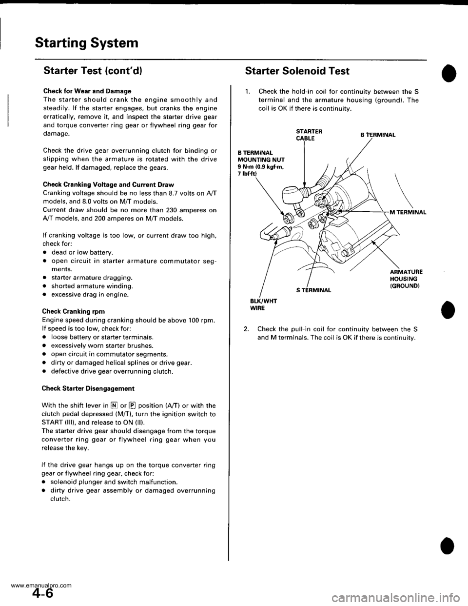
Starter Solenoid Test
1. Check the hold-in coil for continuity between the S
terminal and lhe armature housing (ground). The
coil is OK if there is continuity.
STARTER
B TERMINALMOUNTING NUT9 N.m 10.9 kgtm,7 tbtftl
TERMINAL
ARMATUREHOUSING(GROUND}
BLK/WHTWIRE
Check the pull in coil for continuity between the S
and M terminals. The coil is OK if there is continuity.
2.
4-6
www.emanualpro.com
Page 61 of 1395
I
NOT GOOD
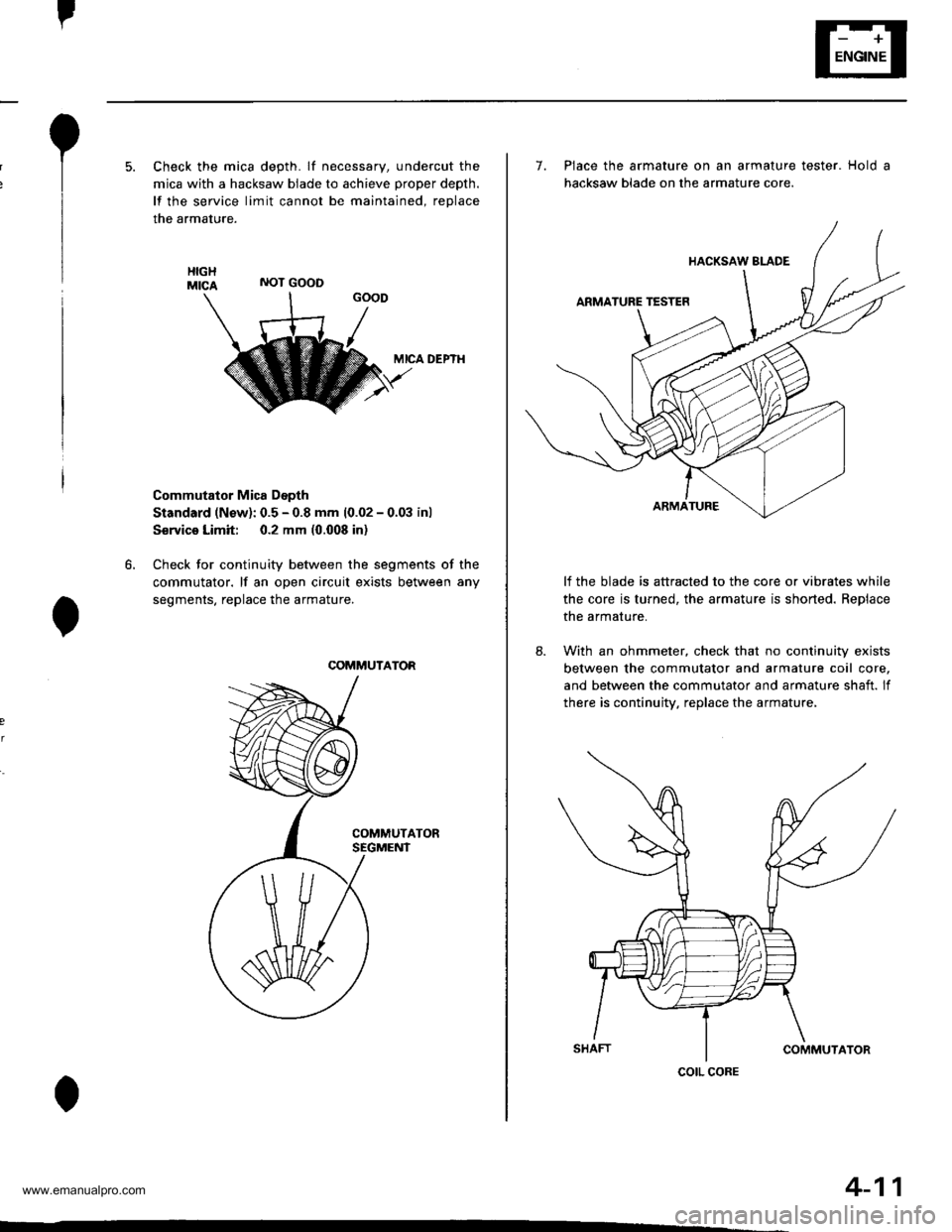
5. Check the mica depth. lf necessary, undercut the
mica with a hacksaw blade to achieve proper depth.
lf the service limit cannot be maintained, reDlace
the armature.
MICA DEPTI{
Commutator Mica Depth
Standard (Nsw): 0.5 - 0.8 mm 10.02 - 0.03 inl
Servico Limit: 0.2 mm (0.008 in)
Check for continuity between the segments of the
commutator. lf an open circuit exists between any
segments. replace the armature.
6.
COMMUTATOR
4-11
7. Place the armature on an armature tester. Hold a
hacksaw blade on the armature core.
lf the blade is attracted to the core or vibrates while
the core is turned. the armature is shorted. Replace
the armature.
8. With an ohmmeter, check that no continuity exists
between the commutator and armature coil core,
and between the commutator and armature shaft. lf
there is continuity. replace the armature,
cotL coRE
www.emanualpro.com
Page 63 of 1395
,r1.?
Performance Test
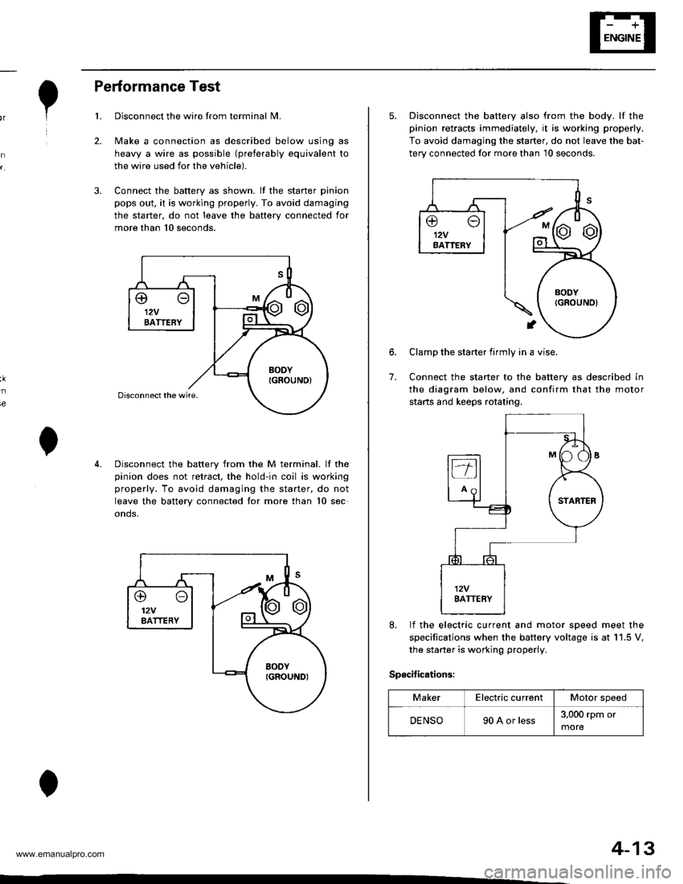
Disconnect the wire from terminal N4.
Make a connection as described below using as
heavy a wire as possible (preferably equivalent to
the wire used for the vehicle).
Connect the battery as shown. lf the starter pinion
pops out. it is working properly. To avoid damaging
the starter, do not leave the battery connected for
more than 10 seconds.
3.
ie
Disconnect the battery from the M terminal. lf the
pinion does not retract, the hold-in coil is working
properly. To avoid damaging the starter, do not
leave the battery connected for more than 10 sec
onds.
@o12VBATTERY
4-13
5. Disconnect the battery also from the body. lf the
pinion retracts immediately, it is working properly,
To avoid damaging the starter, do not leave the bat-
terv connected for more than 10 seconds.
6.
7.
Clamp the starter firmly in a vise.
Connect the starter to the battery as described in
the diagram below, and confirm that the motor
starts and keeps rotating.
8, lf the electric current and motor soeed meet the
specifications when the battery voltage is at 11.5 V,
the starter is working properly.
Specifications:
MakerElectric currentMotor speed
DENSO90 A or less3,000 rpm or
more
www.emanualpro.com
Page 64 of 1395
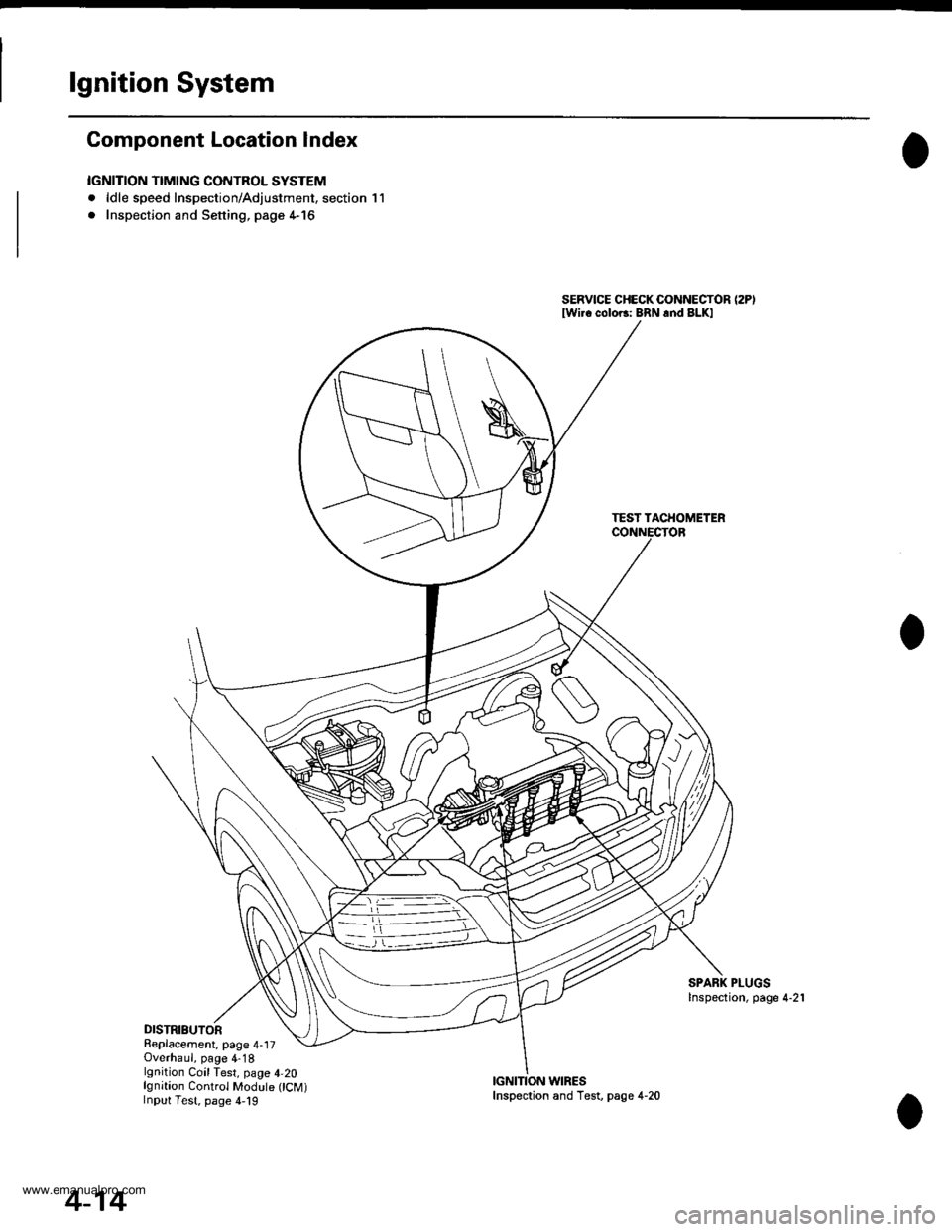
lgnition System
Component Location Index
IGNITION TIMING CONTROL SYSTEM
. ldle speed Inspection/Adjustment, section 11
. Inspection and Sening. page 4-16
DISTRIBUTORReplacement, page 4-17Overhaul, page 4-18lgnition CoilTest, page 4,20lgnition Control Module CM)Input Test, page 4,19
SERVICE CHECK CONNECTOR (2P)
lwi.c colo6: BRN rnd BLKI
TEST TACHOMETER
SPARK PLUGSInspection, page 4-21
WIRES
4-14
Inspection and Test, page 4-20
www.emanualpro.com
Page 67 of 1395
e
o
I'
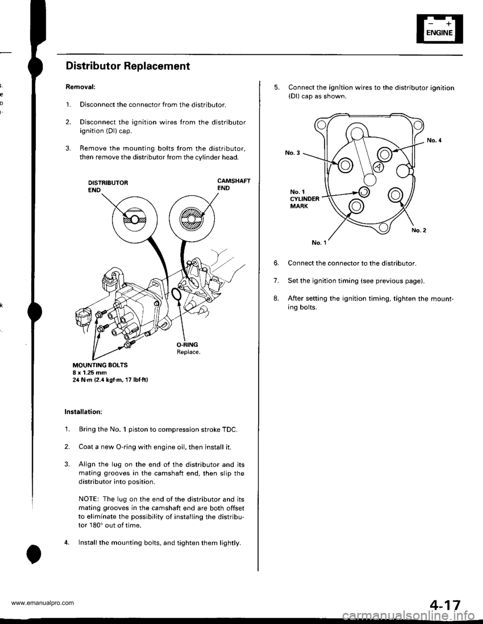
Distributor Replacement
Removal:
1. Disconnect the connector from the distributor.
2. Disconnect the ignition wires from the distributor
ignition (Dl) cap.
3. Remove the mounting bolts from the distributor,
then remove the distributor from the cylinder head.
CAMSHAFTEND
MOUNTING BOLTS8 x 1.25 mm2,1N.m {2.,1kgrf.m, 17 lbf ftl
lnstallation:
1. Bring the No. 1 piston to compression stroke TDC.
2. Coata new O-ring with engine oil, then install it.
3. Align the lug on the end of the distributor and its
mating grooves in the camshaft end, then slip the
distributor into position.
NOTE: The lug on the end of the distributor and its
mating grooves in the camshaft end are both offset
to eliminate the possibility of installing the distribu-
tor 180o out of time.
4. Installthe mounting bolts, and tighten them lightly.
5. Connect the ignition wires to the distributor ignition(Dl) cap as shown,
No. 1CYLINDERMARK
6. Connect the connector to the distributor.
7. Set the ignition timing (see previous page).
8. After setting the ignition timing, tighten the mount-
ing bolts.
4-17
www.emanualpro.com
Page 68 of 1395
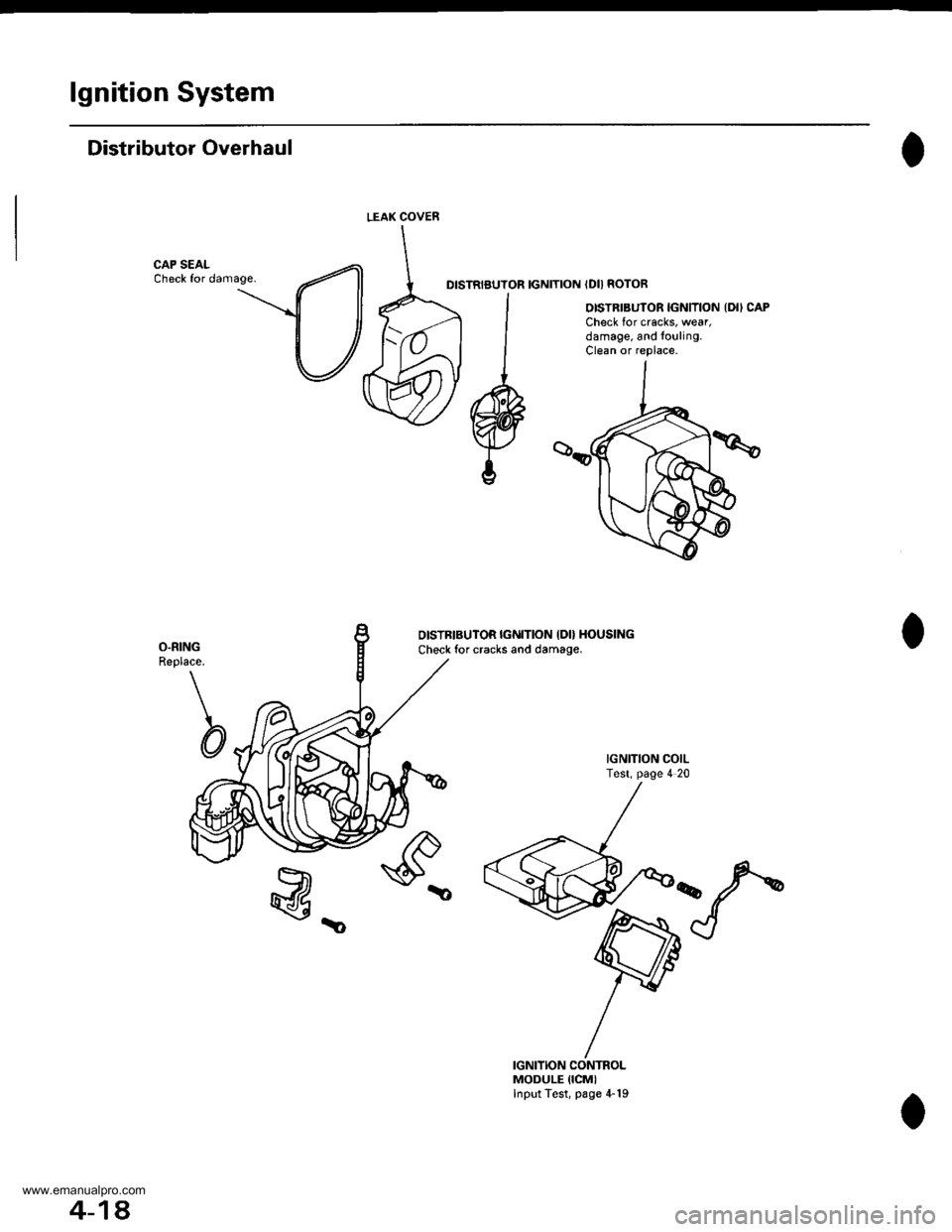
lgnition System
Distributor Overhaul
CAP SEALCheck for damage.DISTRIBUTOR IGNITION IDII ROTOR
OISTRIBUTOR IGNITION {DII CAPCheck for cracks, wear,damage, and to!ling.Clean or replace.
O.RINGReplace.
b
OISTBIBUTOR IGI{ITION IDO HOUSING
Check for cracks and damage.
IGNITION COILTest, page 4 20
@_
IGNITION CONTROLMODULE {ICMIInput Test, page 4-19
LEAK COVEN
4-18.
www.emanualpro.com
Page 69 of 1395
lgnition Control Module (lCMl Input Test
NOTE:
. See section 11 when the malfunction indicator lamp(MlL) comes on.
. Perform an input test for the ignition control module(lCM) after finishing the fundamental tests for the
ignition system and the fuel and emissions systems.
. '97 -'98 models: The tachometer should operate nor-
mally if the ICM is OK.
L Remove the distributor ignition (Dl) cap, the distrib-
utor ignition (Dl) rotor, and the leak cover.
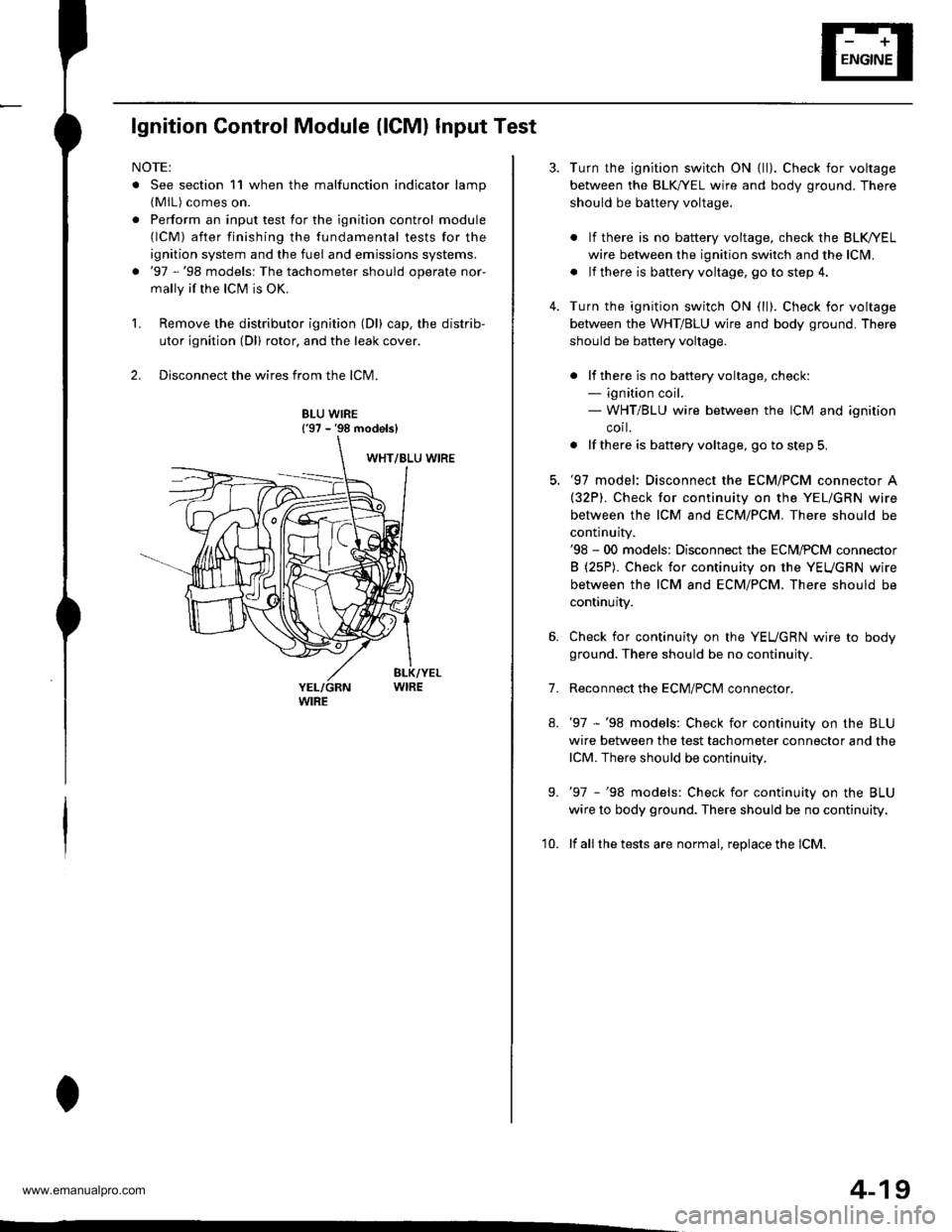
2. Disconnect the wires from the lCM.
8LU WIRE{'97 - '98 models}
4-19
7.
Turn the ignition switch ON {ll). Check for voltage
between the BLK,^/EL wire and body ground. There
should be battery voltage.
. lf there is no battery voltage, check the BLK/rEL
wire betlveen the ignition switch and the lclvl.
. lf there is baftery voltage, go to step 4.
Turn the ignition switch ON (ll). Check for voltage
between the WHT/BLU wire and body ground. There
should be battery voltage.
. lf there is no batteryvoltage, check:- ignition coil.- WHT/BLU wire between the ICM and ignition
corl.
. lf there is battery voltage, go to step 5,
'97 model: Disconnect the ECM/PCM connector A(32P). Check for continuity on the YEL/GRN wire
between the ICM and ECM/PCM. There should be
continuity.'98 - 00 models: Disconnect the ECM,PCM connector
B (25P). Check for continuity on the YEUGRN wire
between the ICM and ECM/PCM. There should be
continuity.
Check for continuity on the YEUGRN wire to body
ground. There should be no continuity.
Reconnect the ECM/PClvl connector.
'97 -'98 models: Check for continuity on the BLU
wire between the test tachometer connector and the
lCM. There should be continuity.
'97 -'98 models: Check for continuity on the BLU
wire to body ground. There should be no continuity.
lf all the tests are normal, replace the lCM.
9.
'10.
www.emanualpro.com
Page 70 of 1395
lgnition System
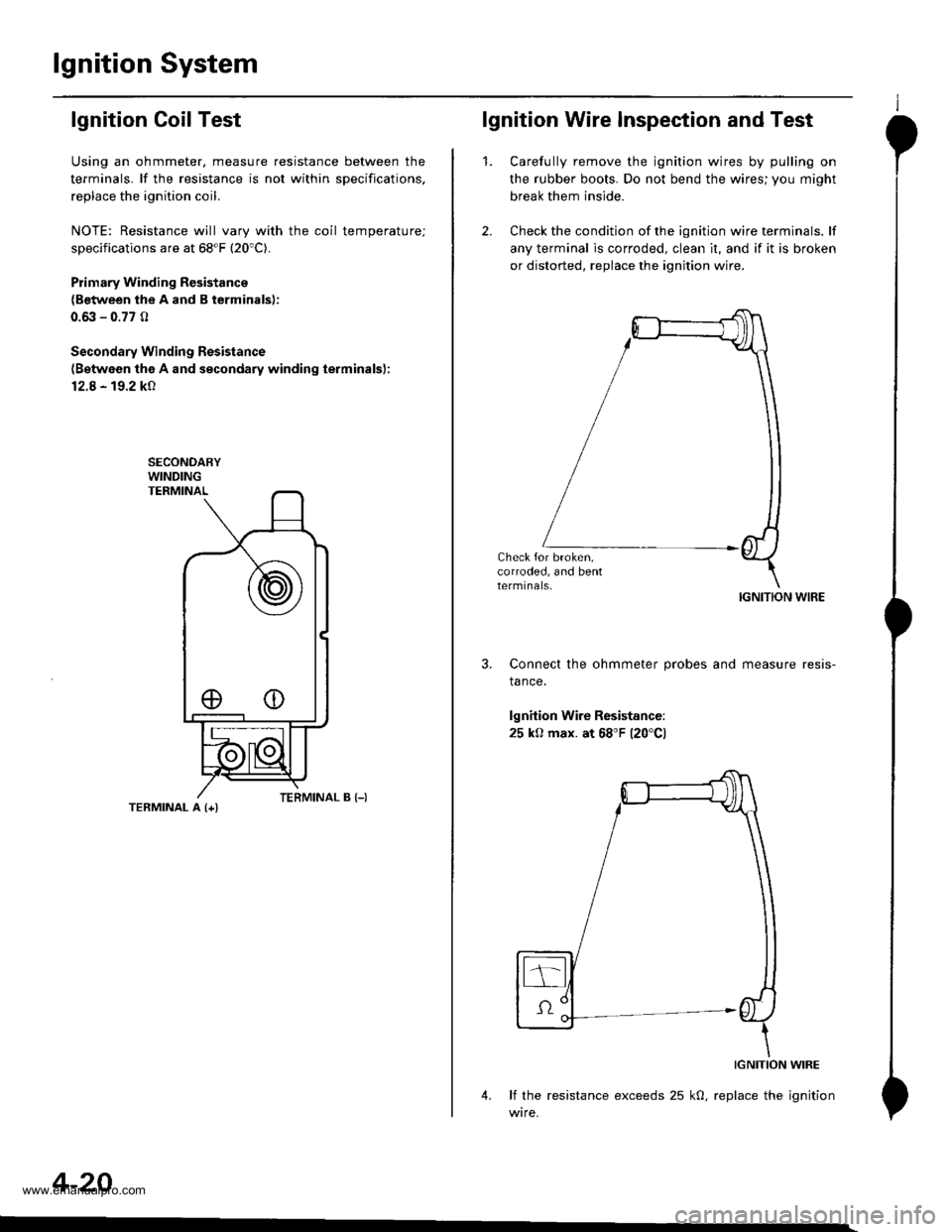
lgnition Coil Test
Using an ohmmeter, measure resistance between the
terminals. lf the resistance is not within sDecifications,
replace the ignition coil.
NOTE: Resistance will vary with the coil temperature;
specifications are at 68"F (20'C).
Plimary Winding Resistance
{Between the A and B terminals):
0.6it - 0.77 0
Secondary Winding Resistance
{Between the A and secondary winding terminals):
12.8 - 19.2 kO
TERMINAL A {+l
4-20
eo
lgnition Wire Inspection and Test
1.Carefully remove the ignition wires by pulling on
the rubber boots. Do not bend the wires; you might
break them inside.
Check the condition of the ignition wire terminals. lf
any terminal is corroded, clean it, and if it is broken
or distorted, replace the ignition wire.
IGNITION WIRE
Connect the ohmmeter probes and measure resis-
tance.
lgnition Wire Resistance:
25 kO max. at 68'F 120'Cl
IGNITION WIRE
4. lf the resistance exceeds 25 kO, replace the ignition
wire.
www.emanualpro.com
Page 71 of 1395
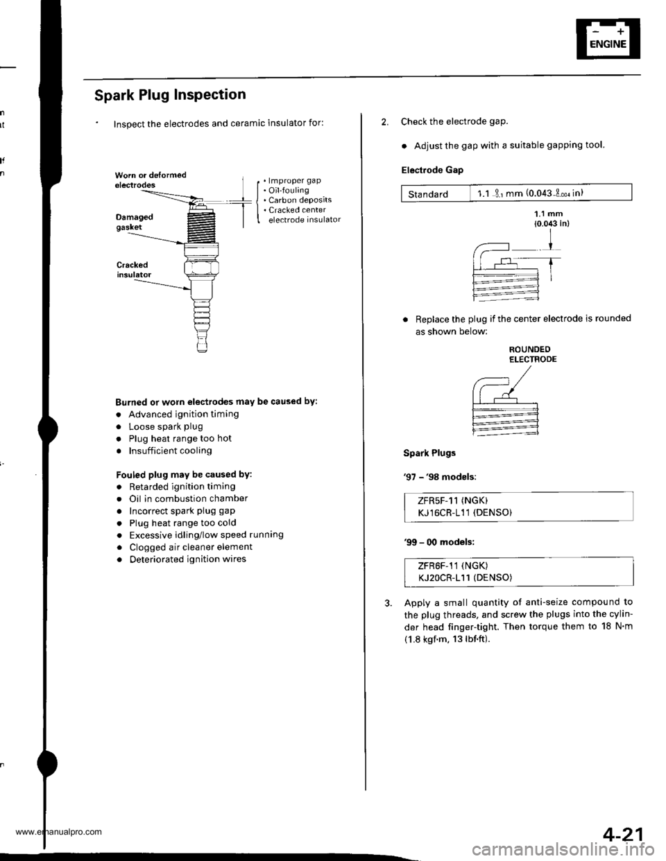
Spark Plug Inspection
Inspect the electrodes and ceramic insulator for:
. lmproper gap. Oil-fouling. Carbon deposits. Cracked centerelectrode insulator
Burned or worn electrodes may be caused by:
. Advanced ignition timing
. Loose spark plug
. Plug heat range too hot
. Insufficient cooling
Fouled plug may be caused by:
. Retarded ignition timing
. Oil in combustion chamber
. Incorrect spark plug gap
. Plug heat range too cold
. Excessive idling/low speed runnang
. Clogged air cleaner element
. Deteriorated ignition wires
I
2. Check the electrode gaP.
. Adjust the gap with a suitable gapping tool.
Electrode Gap
Standard 1.1 3 ' mm (0.043 Loo. in)
Replace the plug if the center electrode is rounded
as shown below:
Spark Plugs
'97 - '98 modsls:
ROUNDEOELECTRODE
,--, /(--/| | r--'--'--r-.--l-:=---:1
:
ZFR5F-11 (NGK)
KJ16CR-111 (DENSO)
'99 - 00 models;
ZFR6F-11 (NGK)
KJ2OCR-111 (DENSO)
Apply a small quantity of anti-seize compound to
the plug threads, and screw the plugs into the cylin-
der head finger-tight. Then torque them to 18 N'm
(1.8 kgf.m. 13lbf.ft).
4-21
www.emanualpro.com