Power HONDA CR-V 1999 RD1-RD3 / 1.G Workshop Manual
[x] Cancel search | Manufacturer: HONDA, Model Year: 1999, Model line: CR-V, Model: HONDA CR-V 1999 RD1-RD3 / 1.GPages: 1395, PDF Size: 35.62 MB
Page 1359 of 1395
Troubleshooting
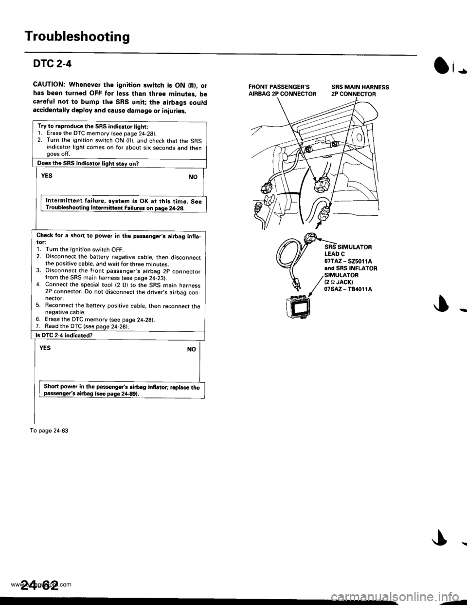
DTC2-4
GAUTION: Wh€never tho ignition switch is ON 0t). orhas been turned OFF for less than threo minutes, bocareful not to bump the SRS unit; the airbags couldaccidentally deploy and cause damaga or iniuriss.
SRS MAIN HARNESS
SIMULAYORLEAD C
Ot-
07TAZ - SZ5011A.nd SRS INFLATOR
/stMU|_ATOR/ t2 tr JAoKI
// olsAz-Tsn11A
ffi
Try to reproduce the SRS indicator light:1. Erase the DTC memory (see page 24-28i.2. Turn the ignition switch ON (lli, and check that the SRSindicator light comes on tor about six seconds and thengoes off.
Do€s the SRS indicator light stay on?
YESNO
Inlermittent tailure, system is OK at this tim€. SceTroubleshooting Intermitt€.f Failures on page 2+28.
Check for a short to power in the passengar,s ai.bag infla-tor:1. Turn the ignition switch OFF.2. Disconnect the baftery negative cable, then disconnectthe positive cable, and wait for three minutes.3. Disconnect the front passenger's airbag 2P connectorIrom the SRS main harness lsee page 24-23).4. Connect the special tool (2 O) to the SRS main harness2P connector. Do not disconnect the driver,s airbag con,nector,5. Reconnect the battery positive cable, then reconnect thenegative cable.6. Erase the DTC memory (see page 24-28).7. Read the DTC (see page 24-26|'.
ls DTC 2-4 indicsted?
YESNO
Sho.t power in the passenger's airbag infator; rsplece thopaisonge/i airbag {s€e pag€ 2il-89).
To page 24-63
24-62
--
www.emanualpro.com
Page 1360 of 1395
Frcm page24-62
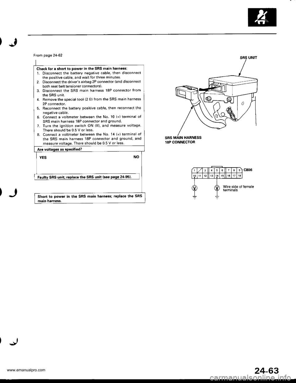
Check lor a short to power in the SRS main harness:
1. Disconnect the battery negative cable, then disconnectthe positive cable, and wait for three minutes.
2. Disconnect the drive/s airbag 2P connector (and disconnect
both seat belttensionerconnectors).3. Disconnect the SRS main harness 18P connector trom
the SRS unit.4. Remove the specialtool (2 0) from the SRS main harness
2P connector,5. Reconnect the batterv positive cable, then reconnect the
negative cable.6. Connect a voltmeter between the No. 10 (+) terminal of
SRS main harness 18P connector and ground.
7. Turn the ignition switch ON (ll). and measure voltage
There should be 0.5 V or less.8. Connect a voltmeter between the No. 141+) terminal of
the SRS main harness 18P connector and ground, and
measure voltage. There should be 0.5 V or less.
Are voltages .3 specifiedT
YESNO
Faulty SRS unit; replace the SRS unit (sce page 24'95).
Short to powor in the SRS main ha.ne3s; replace the SRS
main hdrness.
sRs.I8P CONNECTOR
24-63
www.emanualpro.com
Page 1368 of 1395
)
From page 24-70
Chock tor a short lo power in the sid€ wi.e harness:1. Disconnect the left side wire harness 2P connector fromthe SRS main harness 2P connector.2. Connect the sDecial tool {2 O) to the SRS maan harness2P connector,3. Eraso the DTC memory.4. Read the DTC.
b DTC 3-4 indiclted?
NOYES
Short to power in the left side wire ha.n6ss; replece thenarness.
Check for a short to power in the SRS mein harness:1. Disconnect the negative battery cable, and wait for threemrnutes.2. Disconnect the driver's and lront passenger's airbags,and front passenger's seat belt tensioner connectors (seepage 24-231.3. Disconnect the SRS main harness 18P connector tromthe SRS unit.4. Disconnectthe specialtool(2 0)from the SRS main harness2P connector, then reconnectthe negative battery cable.5. Turn the ignition switch ON (lll.6. Check lor voltage between the No. 4 terminal ol the SFSmain harness '18P connector and body ground. Thereshould be 0.5 V or less. Check for voltage between the No.11 terminals ol the SRS main harness 18P connector. Thereshould be 0.5 V or less.
ls tho voltage as specffied?
YESNO
Faulty SRS unit; replace tho SRS unit lsee paqe 24-95).
Short to power in the SRS m.in harness;.eplace the SRSmain hame3a.
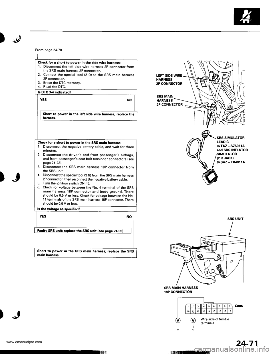
LEFT SIDE WIREHARNESS2P CONNECTOR
SRS MAINHARNESS
h
(
C
00
2P CONNECTOR
SRS SIMULATORLEAO C07TAZ - SZ5011Aand SRS INFLATOR
(2 0 JACKI07SAZ - TB/t011A
)
SRS MAIN HARNESS18P CONNECTOR
)
24-71
www.emanualpro.com
Page 1375 of 1395
Troubleshooting
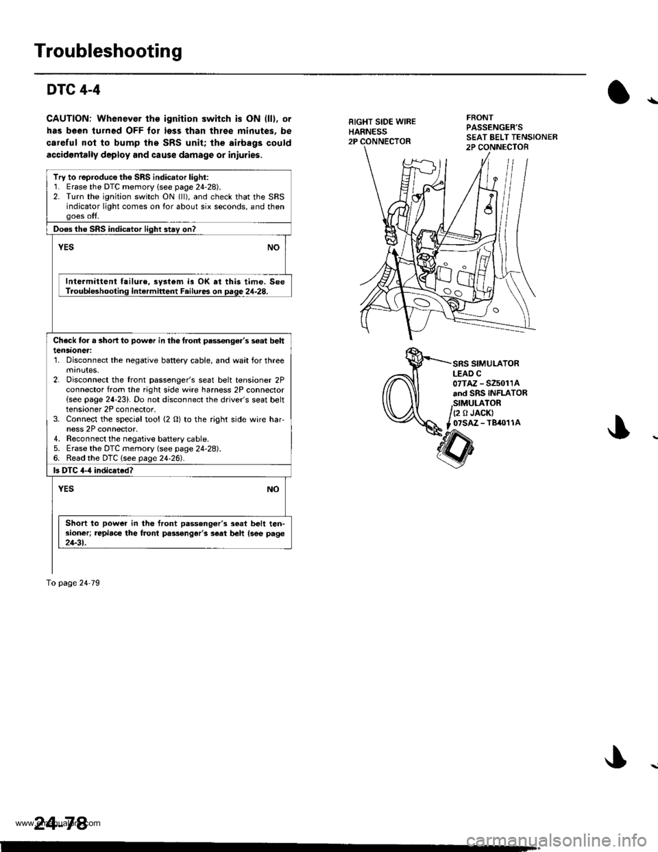
DTC 4-4
CAUTION: Whenever the ignition switch is ON (ll), or
has been turned OFF tor less than thlee minutes. be
careful nol to bump the SRS unit; the airbags could
accidontally deploy and cause damage or iniuries.
RIGHT SIDE WIREHARNESS2P
FRONTPASSENGER'S
SRS SIMULATORLEAD C07TAZ - SZ5011Aand SRS INFLATOR
,StMULATOR/(2 o JACK)
t _07SAZ - TBiro1 1A
Try to reproduce the SRS indicator light:1. Erase the DTC memory {see page 24-28).2. Turn the ignition switch ON (ll), and check that the SRSindicator light comes on for about six seconds, and thengoes off.
Doos the SRS indicator light 3t.y on?
vEsNO
Intermittent f!ilure, system is OK at this time. SeeT.oubleshooting Intermittent F.ilures on page 24-28.
Check tor a 3horl lo power in the frolt pass€nge.'s s€at belttensaoneri'1. Disconnect the negative battery cable, and wait for threemrnutes.2. Disconnect the front passenger's seat belt tensioner 2Pconnector from the right side wire harness 2P connector{see page 24-23}. Do not disconnect the driver's seat belttensioner 2P connector.3. Connect the special tool (2 O) to the right side wire har-ness 2P connector.4. Reconnect the negaiive baftery cable.5. Erase the DTC memory (see page 24-28).6. Read the DTC lsee page24-261.
ls DTC 4-,1 indicated?
YESNO
Short to power in the front passong6r'3 seat belt ten-sioner; replace the front passongar'3 s€at beh {see page21-31.
To page 24'79
24-78.
www.emanualpro.com
Page 1376 of 1395
)
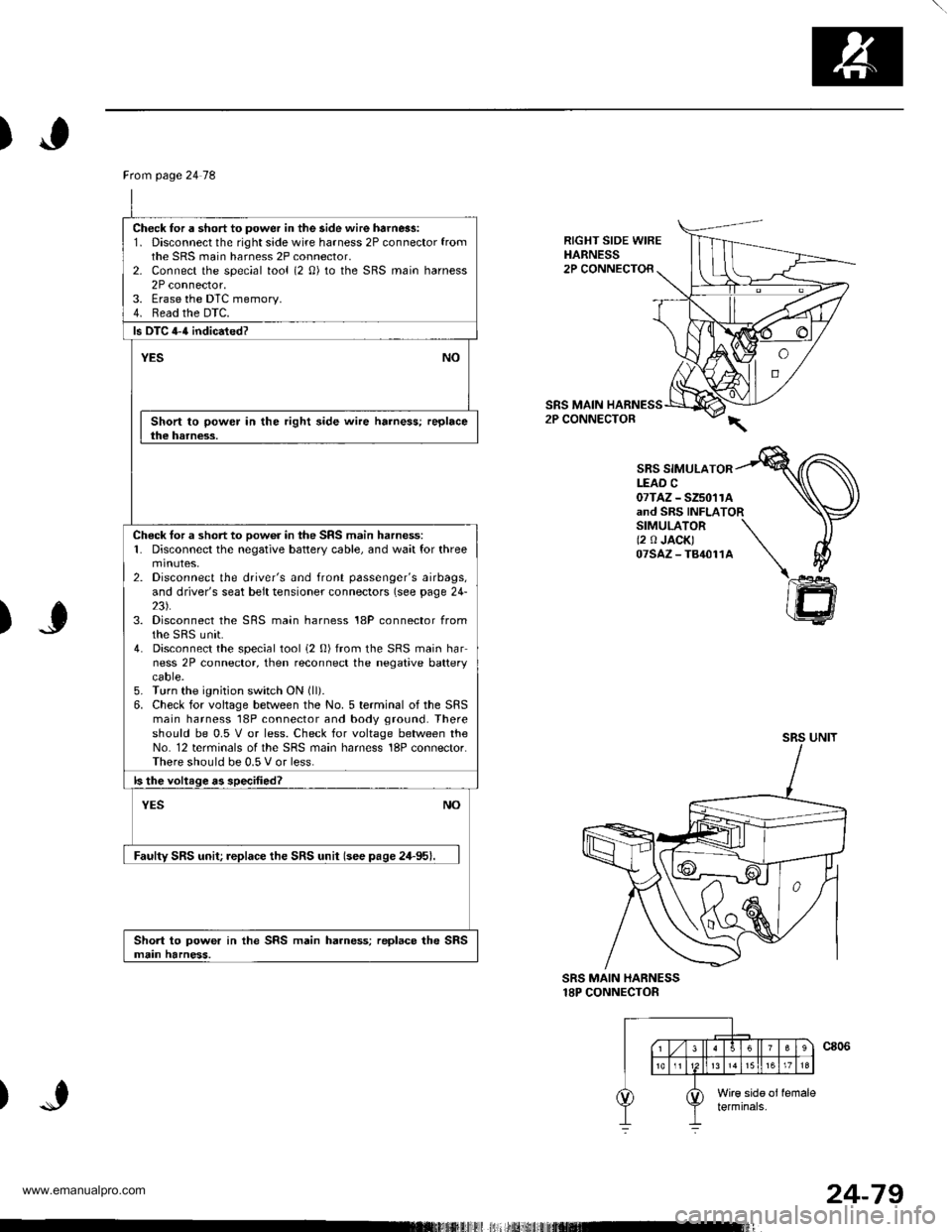
RIGHT SIDE WIREHARNESS2P CONNECTOR
SRS MAIN2P CONNECTOR
SBS SIMULATORLEAD C07TAZ - SZ5011Aand SRS INFLATORSIMULATOR \(2 0 JACK) \07sAz-T84011A \\
)J
)
@
SRS MAIN HARNESS18P CONNECTOR
Ftom page 24 78
Check for a short to power in the side wire harn6s:1. Disconnect the right side wire harness 2P connector fromthe SRS main harness 2P connector,2- Connect the special tool (2 0) to the SRS main harness2P connector.3. Erase the DTC memory.4. Read the DTC.
ls DTC 4-{ indicated?
YESNO
Short to power in the right side wire harness; replacethe harness.
Check tor a short to oow6r in the SRS main harness:1. Disconnect the negative battery cable, and wait for threemtnutes,2. Disconnect the driver's and front passenger's airbags,and driver's seat belt tensioner connectors (see page 24-23).3. Disconnect the SRS main harness 18P connector fromthe sRS unit.4. Disconnect the special tool i2 0) from the SRS main harness 2P connector, then reconnect the negative batterycaore.5. Turn the ignition switch ON (ll).
6. Check for voltage between the No. 5 terminal of the SRSmain harness 18P connector and body ground. Thereshould be 0.5 V or less. Check for voltage between theNo. 12 terminals of the SRS main harness 18P connector.There should be 0.5 V or less.
ls the voltage as specified?
NOYES
Faulty SRS unit; replace the SRS unit (see pase 24-95).
Short to power in the SRS main harness; replace the SRSmain harness.
24-79
www.emanualpro.com
Page 1379 of 1395
Troubleshooting
DTC 8-6 -'97 model
CAUTION: Whonever th€ ignition switch is ON fll). olhas b€en turned OFF for les3 than thro€ minutes, becaretul not to bump the SRS unit; tho airbags couldaccidentally deploy and cause damage or iniurios.
Besides indicating an abnormality in the SRS unit, DTC8-6 may also indicate that two problems equivalent toDTC 1-1 and 2-4, 'l-4 and 2-1, or 1-4 and 2-4 occurred atthe same time. Proceed in the order shown below.
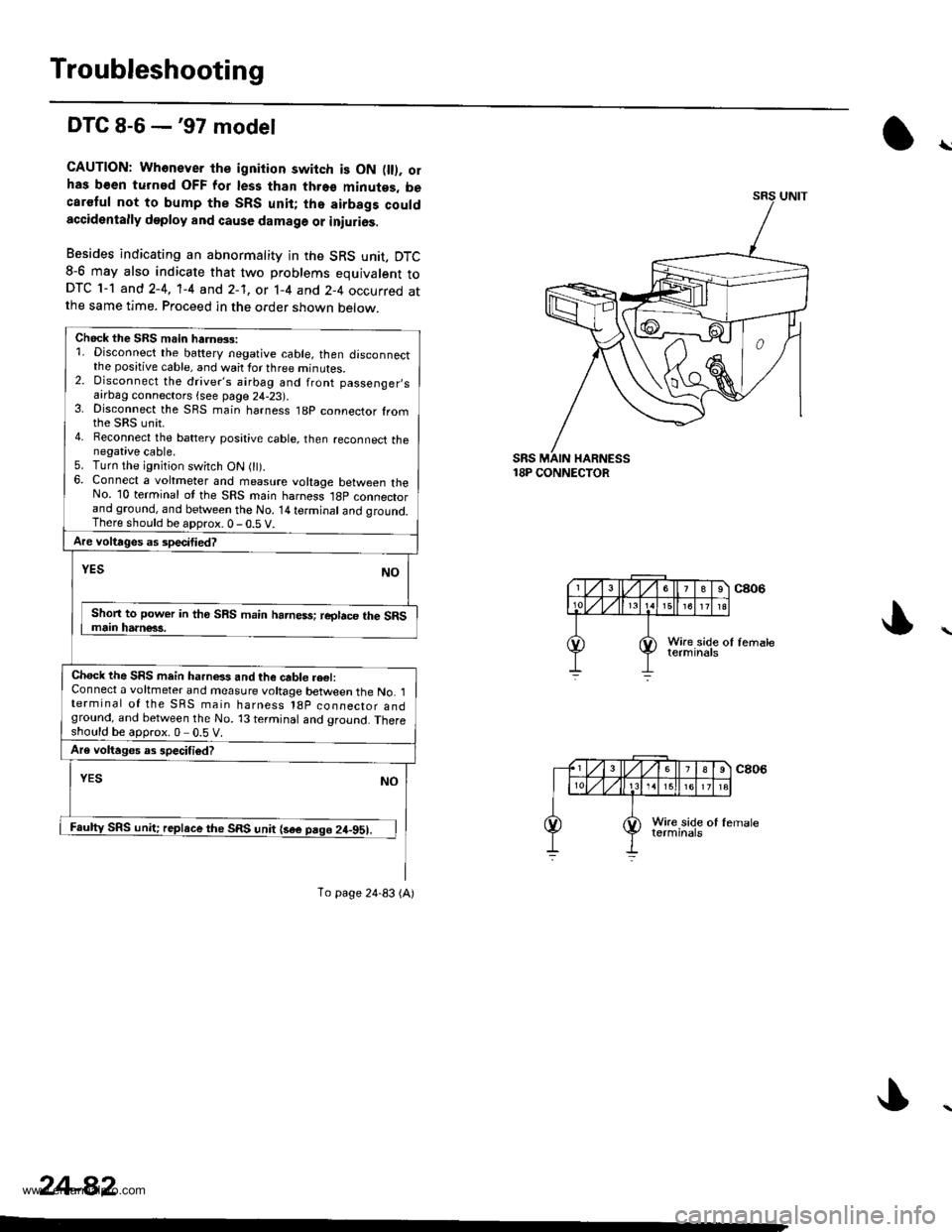
18P CONNECTOR
\
Chock the SBS main harnGs:1. Disconnect the battery negative cable, then disconnectthe positive cable, and wait for three minutes.2. Disconnect the driver's airbag and front passenger,safrDag connectors {see page 24-23).3. Disconnect the SRS main harness t8p connector fromthe sRs unit.4. Reconnect the battery posative cable, then reconnect thenegative cable.5. Turn the ignition switch ON 0t).6. Connect a voltmeter and measure voltage between theNo. 10 terminal ot the SRS main harness l8p connectorand ground, and between the No. 14 terminal and qround.There should be aDorox.0-0.5 V.
Are voltages as specitied?
NOYES
Shon to power in tho SRS main harness; reglace the SRSmain harn€63.
Chock the SRS mein harnels and the cable re€l:Connect a voltmeter and measure voltage between the No. 1terminal of the SRS main harness l8p coonector andground, and between the No. 13 terminal and ground. Thereshould be approx.0 0.5 V.
Are voltages as specifiod?
YESNO
Faulty SRS unit; replace the SRS unit {sae pago 24-951.
To page 24-83 (A)
24-82
www.emanualpro.com