Power HONDA CR-V 1999 RD1-RD3 / 1.G Workshop Manual
[x] Cancel search | Manufacturer: HONDA, Model Year: 1999, Model line: CR-V, Model: HONDA CR-V 1999 RD1-RD3 / 1.GPages: 1395, PDF Size: 35.62 MB
Page 1208 of 1395
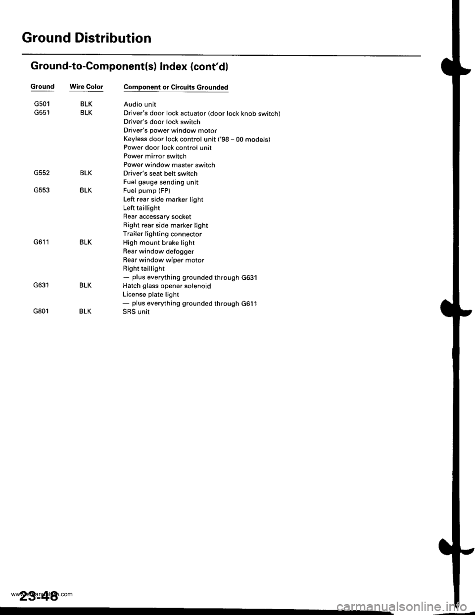
Ground Distribution
Ground-to-Component(sl Index (cont'dl
Wire ColorGround
G552
G501
G801
BLK
BLK
BLK
BLK
Component or Circuits Grounded
Audio unit
Driver's door lock actuator (door lock knob switch)
Driver's door lock switch
Driver's power window motor
Keyless door lock control unit ('98 - 00 models)
Power door lock control unit
Power mirror switch
Power window master switch
Driver's seat belt switch
Fuel gauge sending unit
Fuel pump (FP)
Left rear side marker light
Left taillight
Rear accessary socket
Right rear side marker light
Trailer lighting connector
High mount brake light
Rear window defogger
Rear window wiper motor
Rjght taillight- plus eveMhing grounded through G631
Hatch glass opener solenoid
License plate light- plus eveMhing grounded through G6l1
SRS unit
BLK
BLK
BLK
23-48�
www.emanualpro.com
Page 1212 of 1395
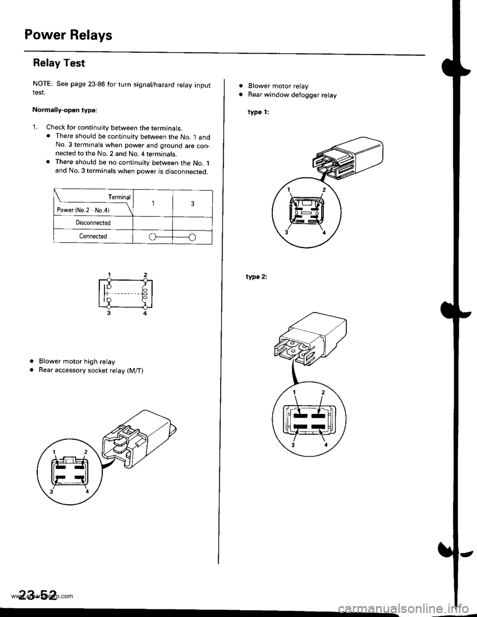
Power Relays
Relay Test
NOTE: See page 23-86 for turn signal/hazard relay inputIESI.
Normally-opon type:
'1. Check for continuity between the terminats.. There should be continuity between the No. I andNo. 3 terminals when power and ground are con-nected to the No. 2 and No. 4 terminals.. There should be no continuity between the No. 1and No. 3 terminals when power is disconnected.
Terminal
t"""r f *r t*i__\l3
Disconnected
Connectedo
a
a
Blower motor high relay
Rear accessory socket relay (M/T)
23-52
ffi
. Blower motor relay
. Rear window defogger relay
type 1:
type 2i
H
al 2 \
Itrrz-Hl
llHrrUll
Y:F,',3 al
www.emanualpro.com
Page 1213 of 1395
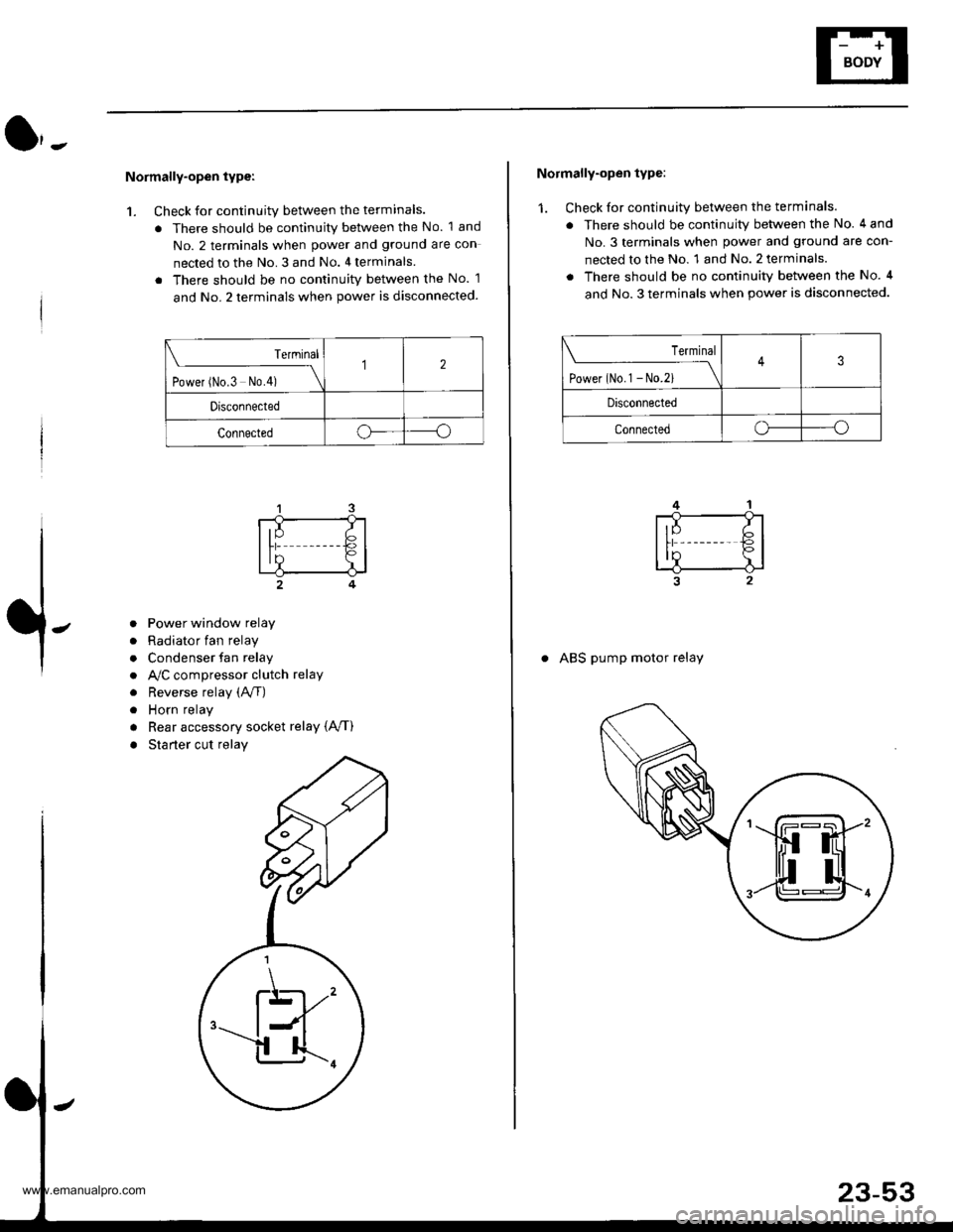
Normally-open type:
1. Check for continuity between the terminals.
. There should be continuity between the No. 1 and
No. 2 terminals when power and ground are con
nected to the No. 3 and No. 4 terminals
. There should be no continuitv between the No. 1
and No. 2 terminals when power is disconnected.
Terminal
t.*", ^"- t*f \
12
Drsconnected
Connectedoo
a
a
a
a
a
a
Power window relay
Radiator fan relay
Condenser fan relay
A,/C compressor clutch relay
Reverse relay (A/f)
Horn relay
Rear accessory socket relay {A,/T)
Starter cut relay
\K,
Normally-open type:
1. Check for continuity between the terminals.
. There should be continuity between the No. 4 and
No.3 terminals when power and ground are con-
nected to the No. 1 and No. 2 terminals.
. There should be no continuity between the No. 4
and No. 3 terminals when power is disconnected.
Terminal
tl**^-*
-_\3
Disconnected
Connectedo----o
. ABS pump motor relay
www.emanualpro.com
Page 1225 of 1395
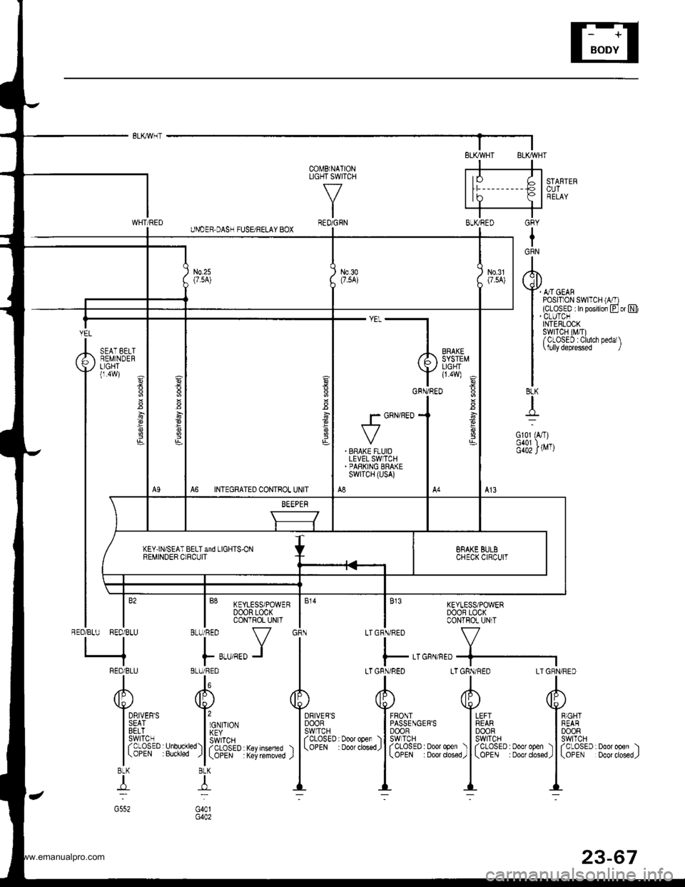
< - ELK/WHT
S'TARTEBCUTRELAY
A,/rGEARPOSrr 0N SWTTCH(CLOSED :ln postion Eor N)
COMBINATONLIGHT SWITCH
\-/
IRED/GRN
I
.l-
NTEGRATED CONTROL UNIT
POWERDOOR LOCKCONTROL UNIT
I B1o PowERBLU/RED DOOR LOCK
I CONTFOL UN T
IY
F r,r'tro J
BLUi RED
"l\
u/
llon. no*
155,1'*IaCLOSED Keylnseded
| \oPEN Key rcmoved
8LK
4
G40r
LTGRN/RED LTGRN/RED LTtl
/rh d[)v !s-l
I FFONT I LEFTI PASSENGEBS I REABI DOOR | 00ORoDen ) lSwlTcH I SWITCHdosedJ J f C-OSED : ooot ooer ) | f CLOSED : Door opel
| ( ooE Doot dosed,r | \oPEN Doo' closed
tl_L -._:-
1,,,,,"
Yilei'rGRN/RED
. BNAKE FLUIOLEVEL SWITCH.PARKING ERAKEswrTcH (usA)
A8
BRAKE BULBCHECKCIFCUTKEY.IN]SEAT BELT and LIGHTS'ONREMINDER C RCU T
23-65
www.emanualpro.com
Page 1227 of 1395
GRY
IGRN
I
rql)
Y4-orotI POSTT1ON SWTTCH (A/T)I (cLosED In posrlion Eor NII . CLUTCNI INTERLOCKI swrTcH (M,T)I /CLOSED :Clulch Dedal\
| \lullydeprsssed I
II8LK
{
Gl01 (A,T)
f;iillrvrr
-"'-},,,,,"
Y l1eff E
v**JT"
g
' BFAKE FLUIDLEVEL SWITCH'PARKING BRAKEswrTcH (usA)
A8A6 INTEGRATED CONTROL UNIT
KEY]N/SEAT BELT and LIGHTS.ONREMINDER CLRCUIT
COMBlNATIONLIGHT SWIlCH
\-7
IREO/GFN
KEYLESS/POWERDOOB LOCKCONTROL UNlT
V
GFN/nED+-]
LTGRN/R€D LT GRN/RED
tl
d[' 4P'\\s.i
EF's l*'n IFF^I'
13fft" l39P*:Door oper ) | fCLOSED. Doo'open ) | fCLO#D. Door ooe. ). Door dos€d,
I
\oPE . 000' closed,
|
\oPE Door ciosed,
ll-- --
,,,[:
ltrh::ffIxl,,'.l'"
l*,*,J IBLU/ BED I
AA
Y Y*,u,.,
I cvro | Bft_oi|l
sl:$P)l lHfi.#' Hrtrff"% ) l
(3!?i".
TI:l
G40tG402
6
DRIVER'SSEATBELTswrTcHrcLosED(OPEN
YEL
RED/BLU
SEAT EELTREM NDERLIGHT(1.4W)
\-
i
I
:
*,
/BLU RED/BLU
q
FEO/BLU
I
dF)
Y*lsE
13fr
l(3BtK
4
www.emanualpro.com
Page 1240 of 1395
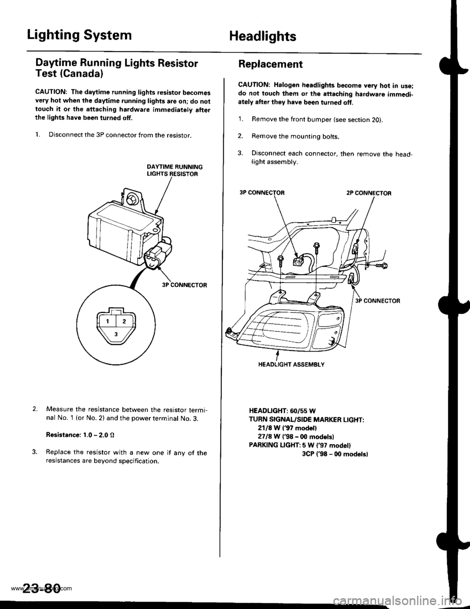
Lighting SystemHeadlights
Dafime Running Lights Resistor
Test (Canada)
CAUTION: The d.ytime running lights resistor becomesvery hot when the daytime running lights are on; do nottouch it or the attaching hardware immediately allerthe lighls have been turned off.
1. Disconnect the 3P connector from the resistor.
Measure the resistance between the resistor termi-nal No. 1 (or No. 2) and the power terminal No. 3.
Resistance: 1.0 - 2.0 O
Replace the resistor with a new one if any of theresistances are beyond specification.
23-80
Replacement
CAUTION: Halogen headlights bGcome very hot in use;do not touch them or the attaching hardware immedi-ately after they have been turned oft.
1. Remove the front bumper (see section 2O).
2. Remove the mounting bolts.
3. Disconnect each connector, then remove the head-light assembly.
HEADLIGHT: 60/55 W
TURN SIGNAL/SIDE MARKER LIGHT:
2118 W {37 model}
2718 W ('98 - 00 modelsl
PARKING LIGHT:5 W l'97 modell
3CP {'98 - 00 modelsl
HEADLIGHT ASSEMELY
www.emanualpro.com
Page 1259 of 1395
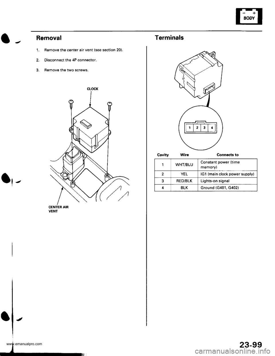
Removal
1. Remove the center air vent (see section 20).
2, Disconnect the 4P connector.
3. Remove the two screws.
CENTER AIRVENT
CLOCK
IIt
-
23-99
Terminals
Connects to
IWHT/BLUConstant power (time
memory)
YELlG1 (main clock power supply)
RED/BLKLights-on signal
4BLKGround {G401, G402}
www.emanualpro.com
Page 1262 of 1395
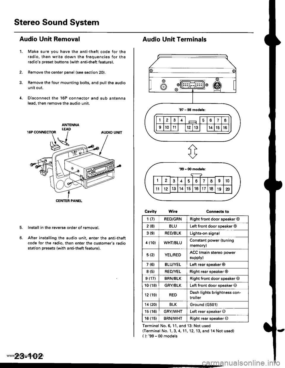
Stereo Sound System
Audio Unit Removal
Make sure you have the anti-theft code for the
radio, then write down the frequencies for the
radio's preset buttons (with anti-theft feature).
Remove the center panel (see section 201,
Remove the four mounting bolts, and pull the audio
unit out.
Disconnect the 'l6P connector and sub antenna
lead, then remove the audio unit.
Install in the reverse order of removal.
After installing the audio unit, enter the anti-theft
code for the radio. then enter the customer's radio
station presets (with anti-theft feature).
1.
AUDIO UNIT
CENTEB PANEL
23-102
Audio Unit Terminals
CavrtyWireConnoct3 to
Terminal No.6, 11, and 13: Not used(Terminal No. 1,3, 4,'11,12, 13, and '14 Not us6d)
{ ): '99 - 00 models
1{7)RED/GRNRight front door speaker @
2 {8}BLULeft front door speaker @
3 {9)RED/BLKLights-on signal
4 (10)WHT/BLUConstant power (tuning
memory)
5 (2)YEUREDACC (main sterso power
supplyl
7 (6)BLU/YELLeft rear soeaker @
8 (s)RE D/VELRight rear speaker @
9 (17)BRN/BLKRiqht f.ont door speaker O
10 (18)GRY/BLKLeft front door soeaker O
12 (19)REDDash lights brightness con-
troller
14 (20)BLKGround (G501)
15 (16)GRYMHTLeft rear speaker O
16 (15)BRN^ll/HTRight resr speaker O
www.emanualpro.com
Page 1265 of 1395
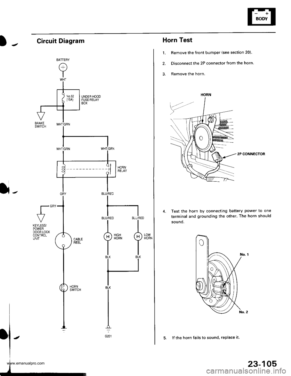
Horn Test
1. Remove the front bumper (see section 20).
2. Disconnect the 2P connector from the horn
3, Remove the horn.
2P CONNECTOR
Test the horn by connecting battery power to one
terminal and grounding the other. The horn should
sound.
4.
HORN
23-105
5. lf the horn fails to sound, replace it
Circuit Diagram
}-BLU/FED
I
BLUi FEO BLU/RED
II
g)iirrN I
tlBLK BLK
ll
IBLK
I
I
I
G201
fl"'
LOWHORN
KEYLESSiPOWEFDOOR LOCKCONTROLUNIT
www.emanualpro.com
Page 1267 of 1395
![HONDA CR-V 1999 RD1-RD3 / 1.G Workshop Manual
Power Mirrors
Circuit Diagram
IGNITION SWITCH
lBAI \-€l ^rc2l.Y
YEL
I
-t----t
I lu.x I
IBLKIryEL
@"*
POWEN MIRRON SWTCH
UNDER,DASHFUSE/RELAYB0x
GRN vHT +l
35
BLK
-:
G551
l,-
[ ] : 9&00 rnodels
U HONDA CR-V 1999 RD1-RD3 / 1.G Workshop Manual
Power Mirrors
Circuit Diagram
IGNITION SWITCH
lBAI \-€l ^rc2l.Y
YEL
I
-t----t
I lu.x I
IBLKIryEL
@"*
POWEN MIRRON SWTCH
UNDER,DASHFUSE/RELAYB0x
GRN vHT +l
35
BLK
-:
G551
l,-
[ ] : 9&00 rnodels
U](/img/13/5778/w960_5778-1266.png)
Power Mirrors
Circuit Diagram
IGNITION SWITCH
lBAI \-€l ^rc2l.Y
YEL
I
-t----t
I lu.'x I
IBLKIryEL
@"*'
POWEN MIRRON SWTCH
UNDER,DASHFUSE/RELAYB0x
GRN vHT +l
35
BLK
-:
G551
l,-
[ ] : '9&00 rnodels
UNDER.HOOD FUSURELAY BOX
N0.41 (100A) N0.42 (40A)WHT/8LK +WHT
YEUREDBLUMHT
-
23-107
www.emanualpro.com