ground HONDA CR-V 1999 RD1-RD3 / 1.G Workshop Manual
[x] Cancel search | Manufacturer: HONDA, Model Year: 1999, Model line: CR-V, Model: HONDA CR-V 1999 RD1-RD3 / 1.GPages: 1395, PDF Size: 35.62 MB
Page 1287 of 1395
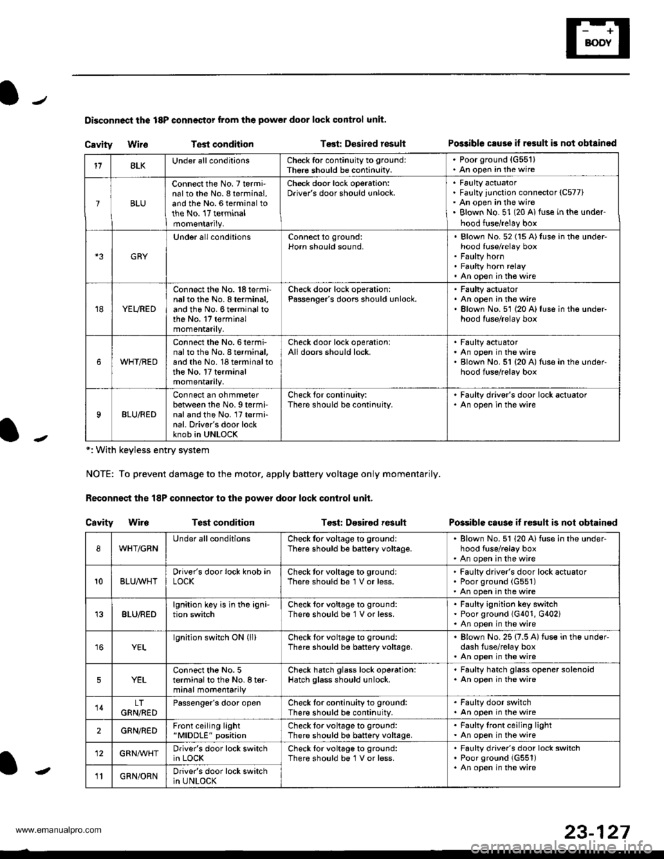
Disconnoci the 18P connestor from the pow€r door lock control unit.
Cavity WireTest conditionTost: Dcsired resultPo$ible csuse il result is not obtainod
Possible cause if result is not obtain€d
*: With keyless entry system
NOTE: To prevent damage to the motor, apply battery voltage only momentarily.
Feconnoct the 18P conneqtor to the power door lock control unit,
Cavity Wir6Test conditionTost: D€sirod result
118LKUnder all conditionsCheck for continuity to ground:
Ther€ should be continuity.
. Poorground (G55'l). An open in the wire
7BLU
Connect the No. 7 termi'nalto the No. 8 terminal,and the No. 6 terminal tothe No. 17 terminalmomentarily.
Check door lock operation:Driver's door should unlock.Faulty actuatorFaulty junction connector (C577)
An open in the wireBlown No. 51 (20 Al{use in the under-
hood fuse/relay box
GRY
Under all conditionsConnect to ground:Horn should sound,Blown No. 52 (15 A)tuso in the under-hood fuse/relay boxFaulty hornFaulty horn relayAn open in tho wire
YEURED
Connect the No. 'l8 termi-nalto the No. 8 terminal,and the No. 6 terminal tothe No. 17 terminalmomentarily.
Check door lock operation:Passenger's doors should unlock.Faulty actuatorAn open in the wireBlown No.51 (20 A)fuse in the under-hood fuse/relay box
WHT/RED
Connect the No.6termi-nal to th6 No. I terminal,and the No. 18 terminal tothe No. 17 terminalmomentarily.
Check door lock operationlAll doors should lock.Faulty actuatorAn open in the wireBlown No. 51 {20 A) fuse in ihe under-hood fuse/relay box
9BLU/RED
Connect an ohmmeterbetween the No. 9 termi-nal and the No. l7 termi-nal. Driver's door lockknob in UNLOCK
Check for conlinuity:There should be continuity.
' Faulty driver's door lock actualor. An open in the wire
WHT/GRNUnder all conditionsCheck for voltage to ground:
There should be battery voltage.Blown No. 51 (20 Alfuse in the under-hood tuse/relay boxAn open in the wire
10BLUAVHTDriver's door lock knob inLOCKCheck tor voltage to ground:There should be 1 V or less.Faulty driver's door lock actuatorPoor ground (G551)
An open in the wire
13BLU/REDlgnition key is in the igni-tion switchCheck tor voltage to ground:
There should b€ 1 V or less.Faulty ignition key switchPoor ground (G401, G402)An open in the wire
YELlgnition switch ON (ll)Check for voltage to ground:
There should be battery voltage.Blown No. 25 (7.5 A) fuse in the under-dash fuse/relay boxAn open in the wire
5YELConnect the No. 5terminal to the No. I ter-minal momentarily
Check hatch glass lock operation:Hatch glass should unlock.
. Faulty hatch glass opener solenoid. An opon in the wire
14LTGRN,NEDPassengor's door openCheck for continuity to ground:There should b€ continuity.
. Fa(llty door switch. An open in the wire
2GRN/R€DFront ceiling light"MlDDLE" positionCheck tor voltage to ground:There should be battery voltage.Faulty lront ceiling lightAn open in the wire
12GRNAr'VHTDriver's door lock switchin LOCKCheck lor voltage to ground:There should be 1V or less.Faulty driver's door lock switchPoor ground {G551)An open in the wire' GRN/ORNDriver's door lock switchin UNLOCK-
23-127
www.emanualpro.com
Page 1288 of 1395
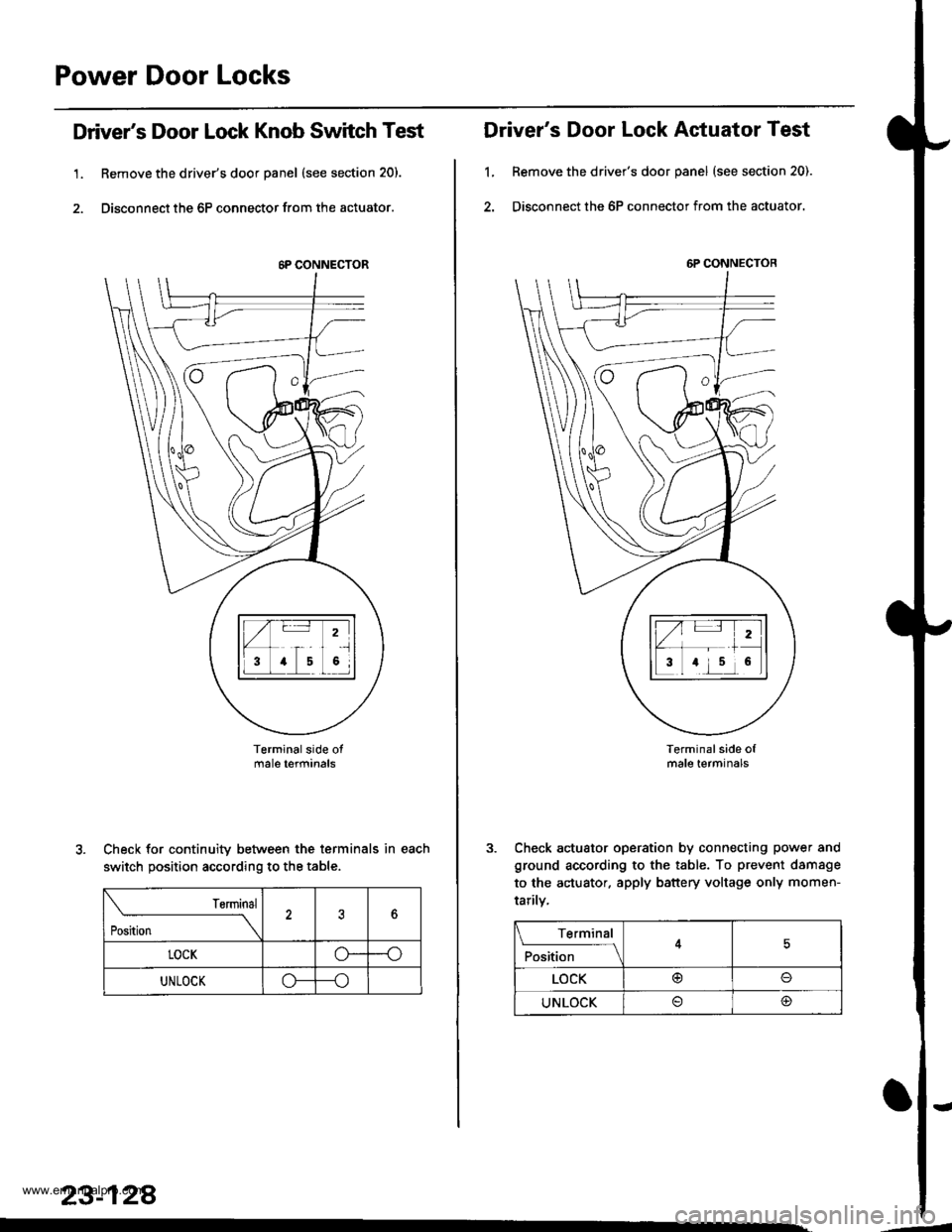
Power Door Locks
Driver's Door Lock Knob Switch Test
1. Remove the driver's door panel (see section 20).
2. Disconnect the 6P connector from the actuator.
Terminalside otmale terfiinals
Check for continuity between the terminals in each
switch position according to the table.
rsrmrnal
Position \
?6
LOCKo--o
UNLOCKo---o
23-128
.
6P CONNECTOR
Driver's Door Lock Actuator Test
1, Remove the driver's door panel (see section 20).
2. Disconnect the 6P connector from the actuator.
Terminal side ofmale terminals
Check actuator operation by connecting power and
ground according to the table. To prevent damsge
to the actuator. apply battery voltage only momen-
tarilv,
6P CONNECTOR
Terminal
F*'',1."
__l
LOCK@o
UNLOCK@
'-
www.emanualpro.com
Page 1289 of 1395
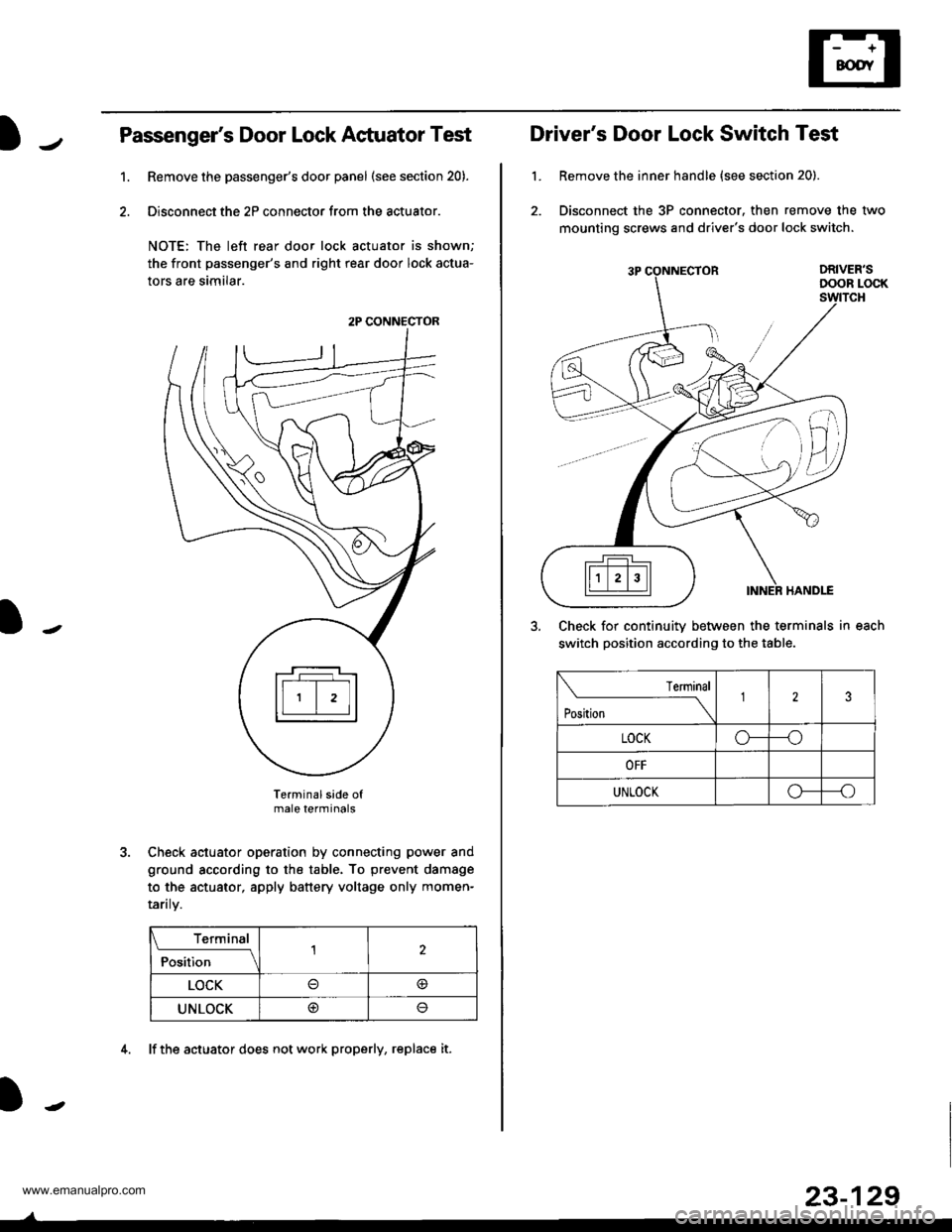
Passenger's Door Lock Actuator Test
Remove the passenger's door panel (see section 20).
Disconnect the 2P connector from the actuator.
NOTE: The left rear door lock actuator is shown;
the front passenger's and right rear door lock actua-
tors are similar.
Terminal side ofmale terminals
Check actuator operation by connecting power and
ground according to the table. To prevent damage
to the actuator, apply battery voltage only momen-
raflry.
Terminal
;;il;--r
,l
LOCK@
UNLOCK@
1.
2P CONNECTOR
4. lf the actuator does not work properly, replace it.
23-129
L
Driver's Door Lock Switch Test
Remove the inner handle {see section 20).
Disconnect the 3P connector. then remove the two
mounting screws and driver's door lock switch.
Check for continuitv between the terminals in each
switch position according to the table.
lermlnal
Position \
123
LOCKo---o
OFF
UNLOCKo--_o
www.emanualpro.com
Page 1295 of 1395
-
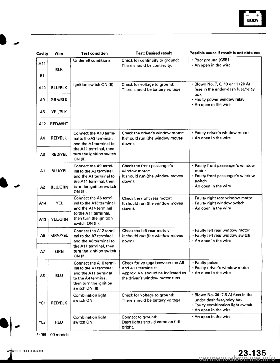
CavityWi1€Test conditionTesi: Dssired rosultPo$ible cause if 183uh is not obtained
A11
BLK
Under all conditionsCheck for continuity to ground:
There should be continuity.
. Poor ground (G551)
. An open in the wire
B1
A10BLU/BLKlgnition switch ON (ll)Check for voltage to ground:
There should be battery voltage.
Blown No. 7, 8, 10 or l1 (20 A)
fuse in the under-dash fuse/relay
box
Faulty power window relay
An open in the wire
A9GRN/BLK
A6YEUBLK
412RED/WHT
A4RE D/BLU
Connect the A10 termi-
nal to the 43 terminal,
and the A4 terminal to
the A11 terminal, then
turn the ignition switch
oN flr).
Check the driver's window motor:
It should run (the window moves
down).
. Faulty driver's window motor
. An open in the wire
A3RED/YEL
A1BLUI/EL
Connect the A9 termi-
nal to the A2 terminal,
and the Al terminal to
the 411 terminal, then
turn the ignition switch
oN flr).
Check the front Passenger'swindow motor:
It should run (the window moves
down).
Faulty front passenger's window
motor
Faulty front passenger's window
switch
An open in the wireA2BLU/ORN
A14YEL
Connect the 46 termi-
nalto the A13 terminal,
and the 414 terminal
to the A11 terminal,
then turn the ignition
switch ON (ll).
Check the right rear motor:
It should run (the window moves
oown).
Faulty right rear window motor
Faulty right window switch
An open in the wire
YEUGRN
A8GBN/YEL
Connect the A12 termi-
nal to the A7 terminat,
and the A8 terminal to
the A11 terminal. then
turn the ignition switch
oN flr).
Check the left rear motor:
,t should run {the window moves
down),
Faulty left rear window motor
Faulty ,eft rear window srrvitch
An open in the wire
GRN
A5BLU
Connect the A10 te.mi-
nal to the 43 terminal,
and the A11 terminal
to the 44 terminal.
then turn the ignition
switch ON (ll).
Check for voltage between the A5
and Al l terminals:
ADorox.6 V should be indicated as
the driver's window motor runs.
Faulty pulser
Faulty driver's window motor
An open in the wire
*clRED/BLK
Combination light
switch ON
Check fo. voltage to ground:
There should be battery voltage.
Blown No.30 (7.5 A) fuse in the
under-dash fuse/relay box
Faulty combination light switch
An open in the wire
RED
Combination light
switch ON
Connect to ground:
Dash lights should come on full
bright.
' An open in the wire
www.emanualpro.com
Page 1297 of 1395
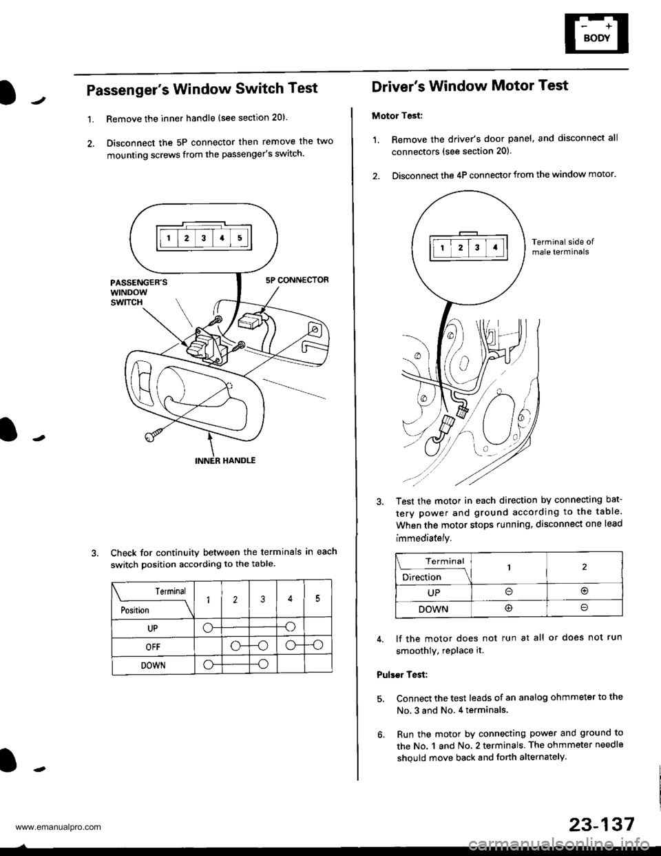
Passenger's Window Switch Test
1.Remove the inner handle (see section 20).
Disconnect the 5P connector then remove the two
mounting screws from the passenger's switch.
Check for continuity between the terminals in each
switch position according to the table
Terminal
;"rL-
__\1235
UPo--o
OFF-oo--o
DOWNo--o
Driver's Window Motor Test
Motor Test:
1. Remove the driver's door panel, and disconnect all
connectors (see section 201.
2. Disconnect the 4P connector from the window motor.
Terminal side ofmale terminals
Test the motor in each direction by connecting bat-
tery power and ground according to the table.
When the motor stops running. disconnect one lead
immediately.
Terminal
;;b"
-\
UPo(!r
DOWN@o
4. lf the motor does not run at all or does not run
smoothly. rePlace it.
Pulser Test:
5. Connect the test leads of an analog ohmmeter to the
No, 3 and No. 4 terminals.
6. Run the motor by connecting power and ground to
the No. 1 and No. 2 terminals. The ohmmeter needle
shquld move back and forth alternately.
23-137
www.emanualpro.com
Page 1298 of 1395
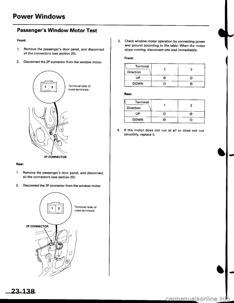
Power Windows
Passenger's Window Motor Test
Front:
l. Remove the passenger's door panel, and disconnect
allthe connectors (see section 20).
2. Disconnect the 2P connector from the window motor.
Rear:
1. Remove the passenger's doo. panel, and disconnect
allthe connectors (see section 20).
2. Disconnectthe 2P connectorfrom the window motor.
23-138
3. Check window motor operation by connecting power
and ground according to the table. When the motor
stops running, disconnect ohe lead immediatelv.
Front:
Terminal
;."b"
.l\
UP@
DOWNo@
R€ar:
I Terminal
;*r*
-l\
UPo@
DOWN@o
lf the motor does not run at all or does not runsmoothly, replace it.
www.emanualpro.com
Page 1312 of 1395
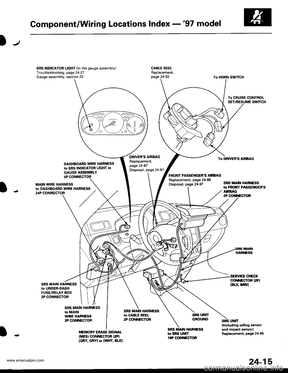
Component/Wiring Locations Index -'97 model
SRS INDICATOR LIGHT (ln the gauge assembly)Troubleshooting, page 24-27Gauge assembly, section 23
DASHBOABD w|RE HARNESS
to SBS INDICATOR LIGHT in
DRIVER'S AIBMGReplacement,page 21-87Disposal, page 24-97
To CRUISE CONTROLSET
To DRIVERS AnBAG
ANBAG2P
sBsitAr[ ] nNEssto FROI|T PASSEiIGEB.S
FRONT PASSEITGER'S AIRBAGReplacement, pago 24{9Disposal, page 24-97
sns ut{fTGROUND
SES MAIN HAR]GSStosns U nItP OOIIITECTOR
MAIN WIRE HABNESSto DASHBOABD wlRE21P
SRS MAIN HABNESSto UNOEB-DASHFUSE/BELAY BOX2P CONNECTOR
GOf$ECrOn PPIlBLr( 8R t
MEMORY ERASE SIGNALIMES) CONNECTOR I2PI[GRY. GRYI or twHT, BLr.l
GAUGE ASSEMBLY5P
HARNESS
SRS MAIN HARNESSto MAINWIRE HARNESS3P OONNECTOR
24-15
www.emanualpro.com
Page 1318 of 1395
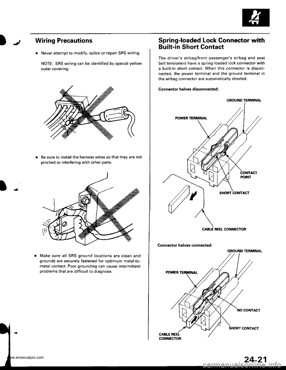
JWiring Precautions
. Never attempt to modify, splice or repair SRS wiring.
NOTE: SRS wiring can be identified by special yellow
outer coveflng.
Be sure to install the harness wires so that they are
pinched or interfering with other parts.
Make sure all SRS ground locations are clean and
grounds are securely fastened for optimum metal-to-
metal contact. Poor grounding can cause intermittent
problems that are difficult to diagnose.
GROUND TERMINAL
CONTACT
CONTACT
24-21
Spring-loaded Lock Connestor with
Built-in Short Gontact
The driver's airbag/front passenger's airbag and seat
belt tensioners have a spring-loaded lock connector with
a built-in short contact. When this connector is discon-
nected, the power terminal and the ground terminal in
the airbag connector are automatically shorted.
Conngctor halvcs diSconnested:
GROUND TERMINAL
SHORT CONTACT
CABIf REEL CONNECTOR
Connector halves connected;
ACT
www.emanualpro.com
Page 1326 of 1395
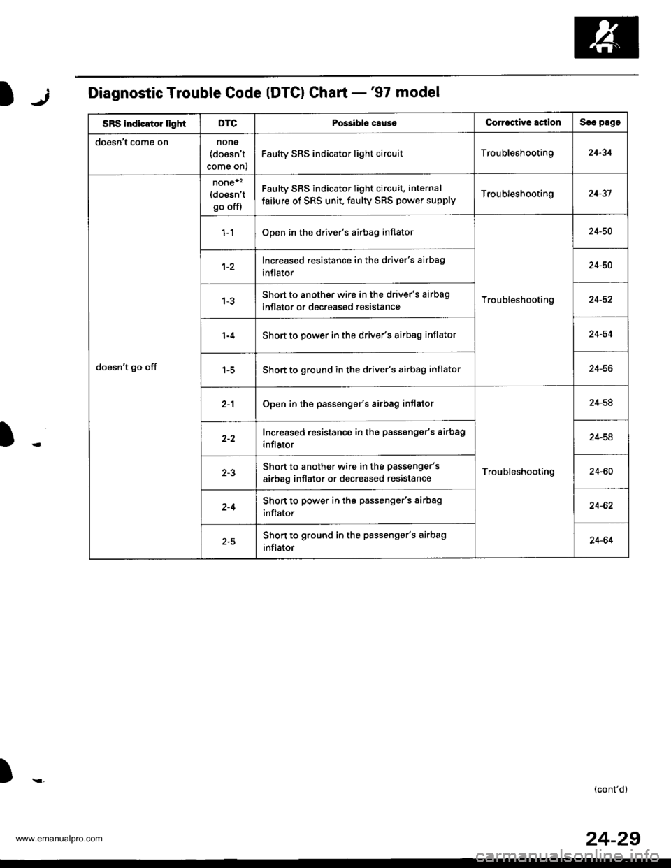
jIDiagnostic Trouble Code (DTG) Ghart -'97 model
SRS indicator lightDTCPos3ibls causeCorroctive actionSlc pago
doesn't come onnone(doesn't
come on)
Faulty SRS indicator light circuitTroubleshooting24-34
doesn't go off
none*'�(doesn't
go off)
Faulty SRS indicator light circuit, internal
tailure of SRS unit, faulty SBS power supplyTroubleshooting24-37
Open in the driver's airbag inflator
Troubleshooting
24-50
Increased resistance in the driver's airbag
inflator24-50
Short to another wire in the driver's airbag
inflator or decreased resistance24-52
Short to power in the driver's airbag inflator24-54
Short to ground in the driver's airbag inflator24-56
Open in the passenger's airbag inflator
Troubleshooting
24-58
Increased resistance in the passenger's airbag
inflator24-54
Shon to another wire in the passenger's
airbag inflator or decreased resistance24-60
2-4Short to power in the passenger's airbag
inflator24-62
2-5Shon to ground in the passengar's airbag
inflator24-64
)r,(cont'd)
24-29
www.emanualpro.com
Page 1328 of 1395
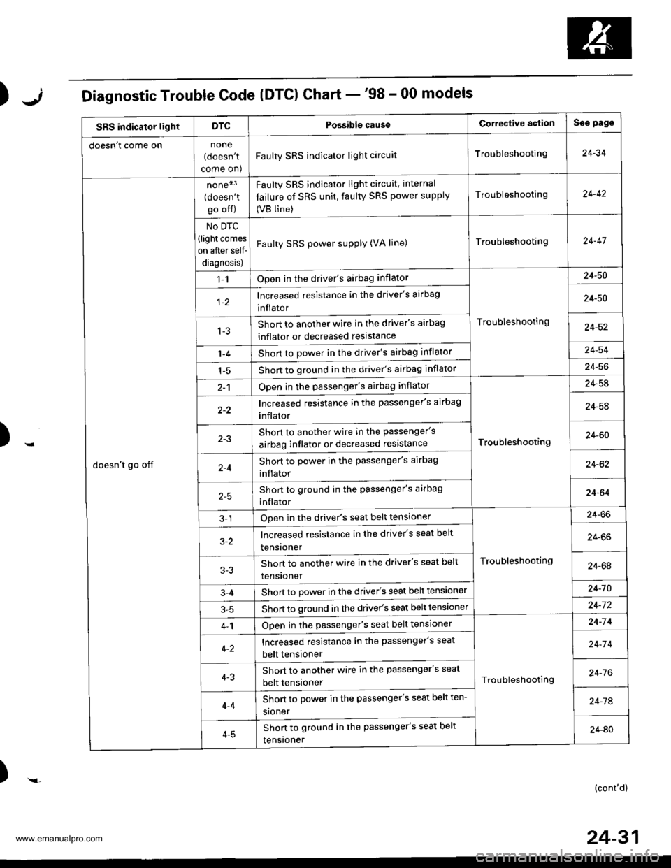
);Diagnostic Trouble Code (DTCI Chart -'98 - 00 models
SRS indicator lightDTCPossibls causeCorrectiva agtionSee page
doesn t come onnone
(doesn't
come on)
Faulty SRS indicator light circuitTroubleshooting24-34
doesn't go off
none*3
{doesn'tgo off)
No DTC
(light comes
on after self-
diagnosis)
Faulty SRS indicator light circuit. internal
failure of SRS unit, faulty SRS power supply
(VB line)
Troubleshooting24-42
Faulty SRS power supply (VA line)Troubleshooting24-47
1-1Open in the driver's airbag inflator
Troubleshooting
24-50
lncreased resistance in the driver's airbag
inflator24-50
1-3Short to another wire in the driver's airbag
inflator or decreased reslstance24-52
1-4Short to power in the driver's airbag inflator24-54
1-5Short to ground in the driver's airbag inflator24-56
2-1Open in the passenger's airbag inflator
Troubleshooting
24-54
Increased resistance in the passenger's airbag
inflator24-58
Shon to another wire in the passenger's
airbag inflator or decreased resistance24-60
2,4Short to power in the passenger's airbag
inflator24-62
Short to ground in the passenger's arrbag
inflator24-64
3-1Open in the driver's seat belt tensioner
Troubleshooting
24-66
3-2lncreased resistance in the driver's seat belt
tensroner24-66
Shon to another wire in the driver's seat belt
tensroner24-64
3-4Short to power in the driver's seat belt tensioner24-10
Short to ground in the driver's seat belt tensloner24-7 2
4-1Open in the passenger's seat belt tensioner
Troubleshooting
24-14
Increased resistance in the passenger's seat
belt tensioner24-7 4
4-3Short to another wire in the passenger's seat
belt tensioner24-7 6
4-4
4-5
Short to power in the passenger's seat belt ten-
sroner24-74
Shon to ground in the passenger's seat belt
tensroner24-AO
)-(cont'd)
24-31
www.emanualpro.com