ground HONDA CR-V 1999 RD1-RD3 / 1.G Workshop Manual
[x] Cancel search | Manufacturer: HONDA, Model Year: 1999, Model line: CR-V, Model: HONDA CR-V 1999 RD1-RD3 / 1.GPages: 1395, PDF Size: 35.62 MB
Page 1352 of 1395
Ftom page24-54
Check for 6 short power in the cable r6el {cont'd):5. Reconnect the battery positive cable, then reconnect thenegative cable.6. Erase the DTC memory (see page 24-28).7. Read the DTC (see page 24-261.
b DTC 1-4 indicarodz
YESNO
Short to power in lhe cablo roel; replace th€ cabl€ ieel{see pago 24-91).
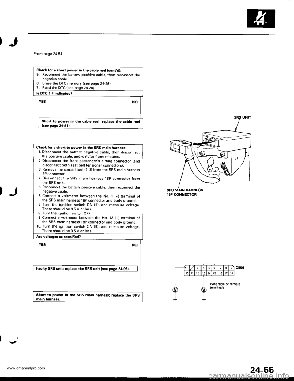
Check tor a short to power in th. SRS main harn$s:1. Disconnect the battery negative cable, then disconnectthe positive cable, and wait for three minutes.2. Disconnect the front passenger's airbag connector {anddisconnect both seat belt tensioner connectors).3. Rernove the special tool (2 O) from the SRS main harness2P connector.4. Disconnect the SRS main harness 18P connector fromthe SRS unit.5. Beconnect the batterv positive cable, then reconnect thenegative cable.6. Connect a voltmeter between the No. 1 {+) terminal olthe SRS main harness 18P connector and body ground.7. Turn the ignition switch ON (ll), and measure voltage.There should be 0.5 V or less.8. Turn the ignition switch OFF.9. Connect a voitmeter between the No. 13 {+i terminal ofthe SRS main harness 18P connector and body ground.10.Turn the ignition switch ON lll), and measure voltage.There should be 0.5 V or less.
Are voltages as specified?
YESNO
Faulty SRS unit; replaco th€ SRS unit lsoo pas6 24-95).
Short to power in th€ SRS main hamoss; roplece the SRSmain haanass.
SRS MAIN HARNESS18P CONNECTOR
24-55
www.emanualpro.com
Page 1353 of 1395
Troubleshooting
DTC l-s
CAUTION: Whenever tho igniiion switch is ON {ll), or
has been lurned OFF for loss lhan thrse minules, be
caretul not to bump the SRS unit; the airbags could
accidentally deploy and cause damage or iniuries.
O'-
DRIVER'S AIRBAG2P CONNECTOR
'97 model:
SRS SIMULATORLEAD C07TAZ - SZ50r1A.nd SRS INFLATORSIMULATOR{2 0 JACK)07sAz - TBaolrA
SRS SIMULATORLEAO C07TAZ - SZ5011Aand SRS INFLATORSIMULATORt2 0 JACKI07sAz - TB{01rA
ar
h/
ffi
'98 - 0O models:
CABLE REEL2P CONNECTOR
Try to reproduce the SRS indicator light:1. Erase the DTC memory (see page 24-28).2. Turn the ignition switch ON lll), and check that the SRSindicator light comes on for about six seconds and thengoes off.
Doos tho SRS indicator liqht stav on?
YESNO
Inte.mittent tailure,3y3tem is OK at this timo. 506Troubleshooling Intermittent Failures on Daq€ 24-28.
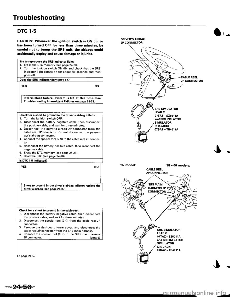
Check tor a short to ground in the driver's ai.bag intlator:1. Turn the ignition switch OFF.2. Disconnect the battery negative cable, then disconnectthe positive cable, and wa:l for three minutes.3. Disconnect the driver's airbag 2P connector from thecable reel 2P connector, Do not disconnect the passen,ger's airbag connector.4. Connect the special tool {2 O} to the cable reel 2P connec-tor.5. Reconnect the battery positive cable. then reconnect thenegative cable.6. Erase the DTC memory (see page 24 28).7. Read the DTC lsee page 24-261.
ls DTC 1-5 indicated?
YESNO
Short to ground in the driver's airbag inflator; replace thedriver's airbag (s6e page 24-871.
Chock for a short to ground in the cablo reel:1. Disconnect the battery negative cable, then disconnectthe positive cable, and wait for three minutes.2. Disconnect the special tool i2 O) from the cable reel 2P
3. Remove the dashboard lower cover, and disconnect thecable reel 2P connector from the SRS main harness.4. Connect the special tool {2 O) to the SRS main harness2P connector. (cont'd)
To page 24-57
24-56
CAALE REEL2P CONNECTOR
J..
.J
www.emanualpro.com
Page 1354 of 1395
)
SRS MAIN HARNESS18P CONNECTOR
)
From page 24 56
Check{or a short to ground in the cable reel (cont'd):
5. Reconnect the batterv positive cable, then reconnect thenegative cable.6. Erase lhe DTC memoty lsee page 24-28).7. Read the DTC lsee page 24 26).
ls OTC 1-5 indicated?
YESNO
Short lo ground in the cable reel; replace the cable reel{see oaoe 2,1-91}.
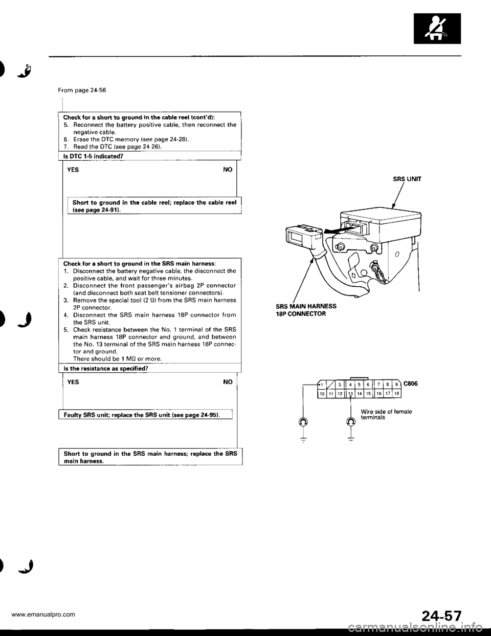
Check for a short to ground in the SRS main harness:'1. Disconnect the battery negative cable, the disconnect thepositive cable, and wait for three minutes.2. Disconnect the tront passenger's airbag 2P connector(6nd disconnect both seat belt tensioner connectors).3. Remove the special tool 12 {))from the SRS main harness2P connector.4- Disconnect the SRS main harness 18P connector fromthe sRs unit.5. Check resistance between the No. l terminal o{theSRSmain harness 18P connector and ground, and betweenthe No. 13 terminal of the SRS main harness 18P connec-tor and ground.There should be I M0 or more.
ls lhe resistance as soecitiod?
NOYES
Faulw SRS unit reDlace the SRS unit lsee paqe 24-951.
Short to ground in the SRS main harness; replace the SRSmain ham€ss,
24-57
www.emanualpro.com
Page 1360 of 1395
Frcm page24-62
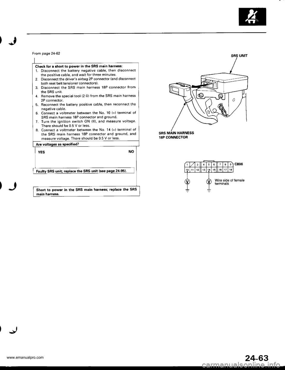
Check lor a short to power in the SRS main harness:
1. Disconnect the battery negative cable, then disconnectthe positive cable, and wait for three minutes.
2. Disconnect the drive/s airbag 2P connector (and disconnect
both seat belttensionerconnectors).3. Disconnect the SRS main harness 18P connector trom
the SRS unit.4. Remove the specialtool (2 0) from the SRS main harness
2P connector,5. Reconnect the batterv positive cable, then reconnect the
negative cable.6. Connect a voltmeter between the No. 10 (+) terminal of
SRS main harness 18P connector and ground.
7. Turn the ignition switch ON (ll). and measure voltage
There should be 0.5 V or less.8. Connect a voltmeter between the No. 141+) terminal of
the SRS main harness 18P connector and ground, and
measure voltage. There should be 0.5 V or less.
Are voltages .3 specifiedT
YESNO
Faulty SRS unit; replace the SRS unit (sce page 24'95).
Short to powor in the SRS main ha.ne3s; replace the SRS
main hdrness.
sRs.I8P CONNECTOR
24-63
www.emanualpro.com
Page 1361 of 1395
Troubleshooting
DTC 2-5
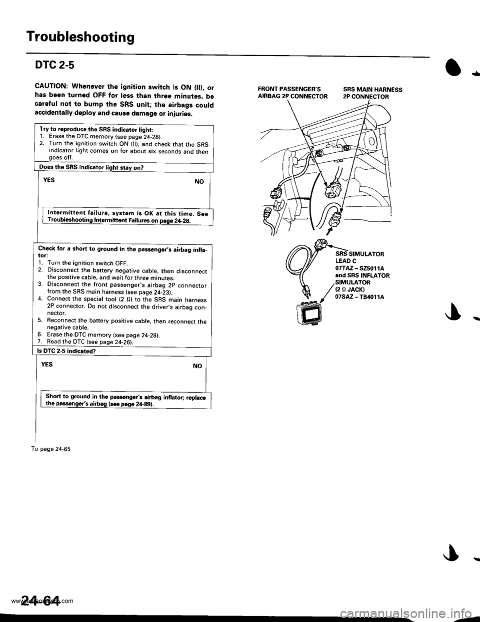
CAUTION: Whenever the igniiion switch is ON {ll}, orhas be€n turn€d OFF for less than three minutes, becareful nol to bump the SRS unit; the sirbags couldaccidentally doploy and causo damage or iniuries.
tl
SIMULATORLEAO C07TAZ - SZ5011A.nd SRS INFLATOR
/StMULATOR/ t2 a JACKI
/ 07saz-fB&11^
ffi
Try to rep.oduce the SRS indicstor tight:1. Erase the DTC memory (see page 24-28).2. Turn the ignition switch ON 0l), and check that the SRSindicator light comes on for about six seconds and thengoes off.
ooes th6 SRS indicaror light st.y on?
YESNO
Inte.mitt.nt failure, system is OK at thi3 time. S€eTroubl6hooting Intermittem Failur6 on page 2+28.
Check for a short to gaound in th6 prsenger,i airbag inlla-tor:1. Turn the ignition switch OFF.2. Disconnect the battery nogative cable, then disconnectthe positive cable, and wait for three minutes.3. Disconnect the front passenger,s airbag 2p connectorfrom the SRS main harness {see page 24-23).4. Connect the special tool (2 0) to the SRS main harness2P connector. Do not disconnect the driver,s airbag con,nector.5. Reconnect the battery positive cable, then reconnect thenegative cable.6. Erase the DTC memory (see page 24-28).7. Read the DTC lsee page 2[-261.
ls DTC 2-5 indicated?
YESNO
Short to ground in the pas€ngert airbeg inflator; ,cplacethe passenge/s airbag (s€e page 2+991.
To page 24 65
24-64
--
www.emanualpro.com
Page 1362 of 1395
)J
From page 24'64
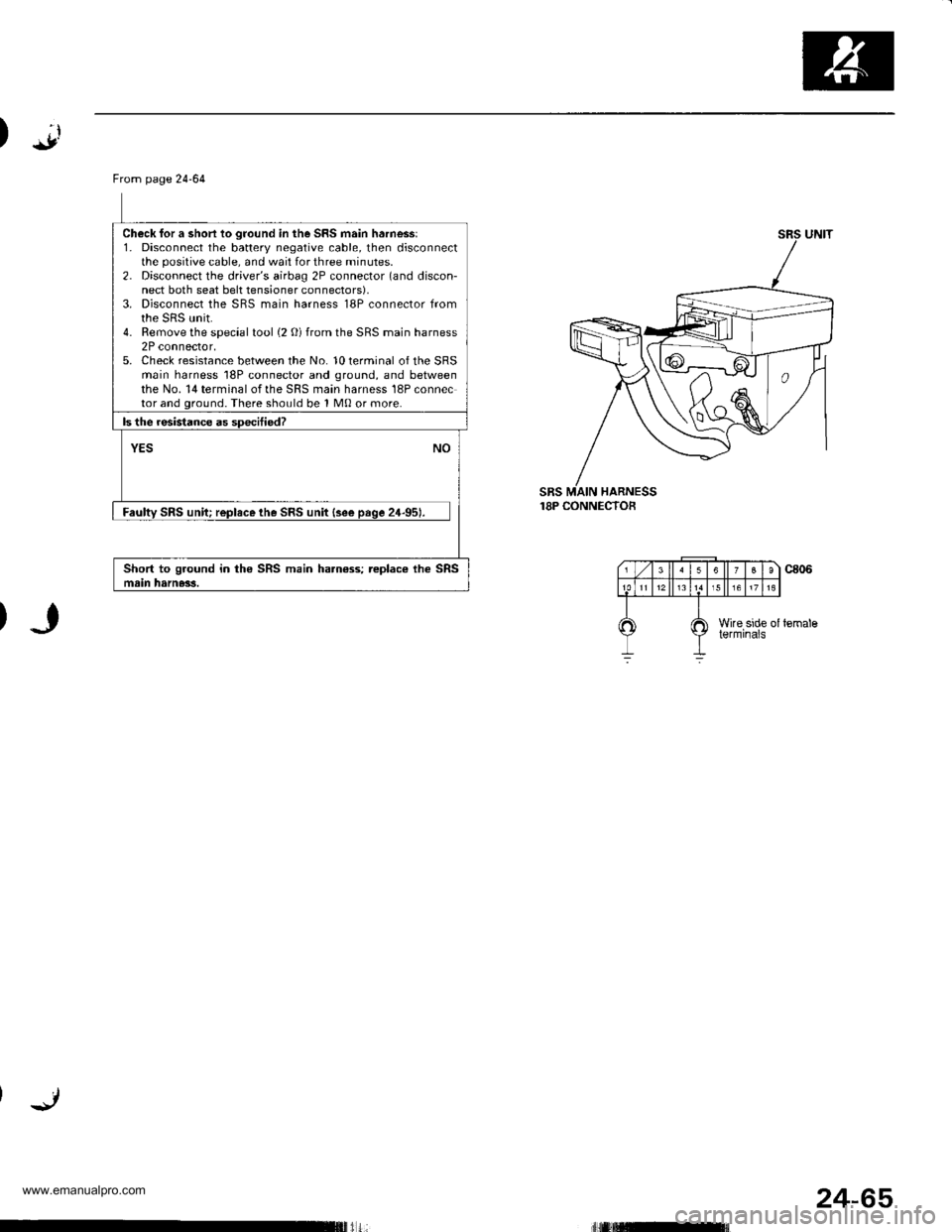
Check for a short to ground in the SRS main harnessl1. Disconnect the battery negative cable, then disconnectthe posilive cable. and wait for three minutes.2. Disconnect the driver's airbag 2P connector (and discon-nect both seat belt tensioner connectors),3. Disconnect the SBS main harness 18P connector fromthe sRs unit.4. Remove the special tool (2 O) from the SRS main harness2P connector,5. Check resistance between the No. 10 terminal of the SRSmain harness 18P connector and ground, and betweenthe No. 14 terminal of the SRS main harness 18P connector and ground. There should be 1 M0 or more.
ls the resistance as sD€citied?
NOYES
Faultv SRS uniu replace the SRS unit {see paqe 24-951.
Short to ground in the SRS main harn€ss; replac€ ihe SRSmain harness.
sRs18P CONNECTOF
24-65
www.emanualpro.com
Page 1368 of 1395
)
From page 24-70
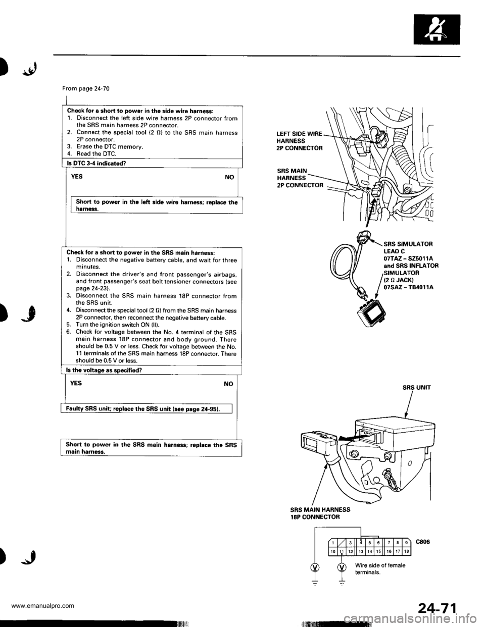
Chock tor a short lo power in the sid€ wi.e harness:1. Disconnect the left side wire harness 2P connector fromthe SRS main harness 2P connector.2. Connect the sDecial tool {2 O) to the SRS maan harness2P connector,3. Eraso the DTC memory.4. Read the DTC.
b DTC 3-4 indiclted?
NOYES
Short to power in the left side wire ha.n6ss; replece thenarness.
Check for a short to power in the SRS mein harness:1. Disconnect the negative battery cable, and wait for threemrnutes.2. Disconnect the driver's and lront passenger's airbags,and front passenger's seat belt tensioner connectors (seepage 24-231.3. Disconnect the SRS main harness 18P connector tromthe SRS unit.4. Disconnectthe specialtool(2 0)from the SRS main harness2P connector, then reconnectthe negative battery cable.5. Turn the ignition switch ON (lll.6. Check lor voltage between the No. 4 terminal ol the SFSmain harness '18P connector and body ground. Thereshould be 0.5 V or less. Check for voltage between the No.11 terminals ol the SRS main harness 18P connector. Thereshould be 0.5 V or less.
ls tho voltage as specffied?
YESNO
Faulty SRS unit; replace tho SRS unit lsee paqe 24-95).
Short to power in the SRS m.in harness;.eplace the SRSmain hame3a.
LEFT SIDE WIREHARNESS2P CONNECTOR
SRS MAINHARNESS
h
(
C
00
2P CONNECTOR
SRS SIMULATORLEAO C07TAZ - SZ5011Aand SRS INFLATOR
(2 0 JACKI07SAZ - TB/t011A
)
SRS MAIN HARNESS18P CONNECTOR
)
24-71
www.emanualpro.com
Page 1369 of 1395
Troubleshooting
DTC 3-5
CAUTION: Whonover tho ignition switch is ON (ll), or
has been turned OFF for less than thres minutes, b€
careful not to bump the SRS unit; the airbags could
accidontally deploy and cause damsgo or iniurirs.
*r
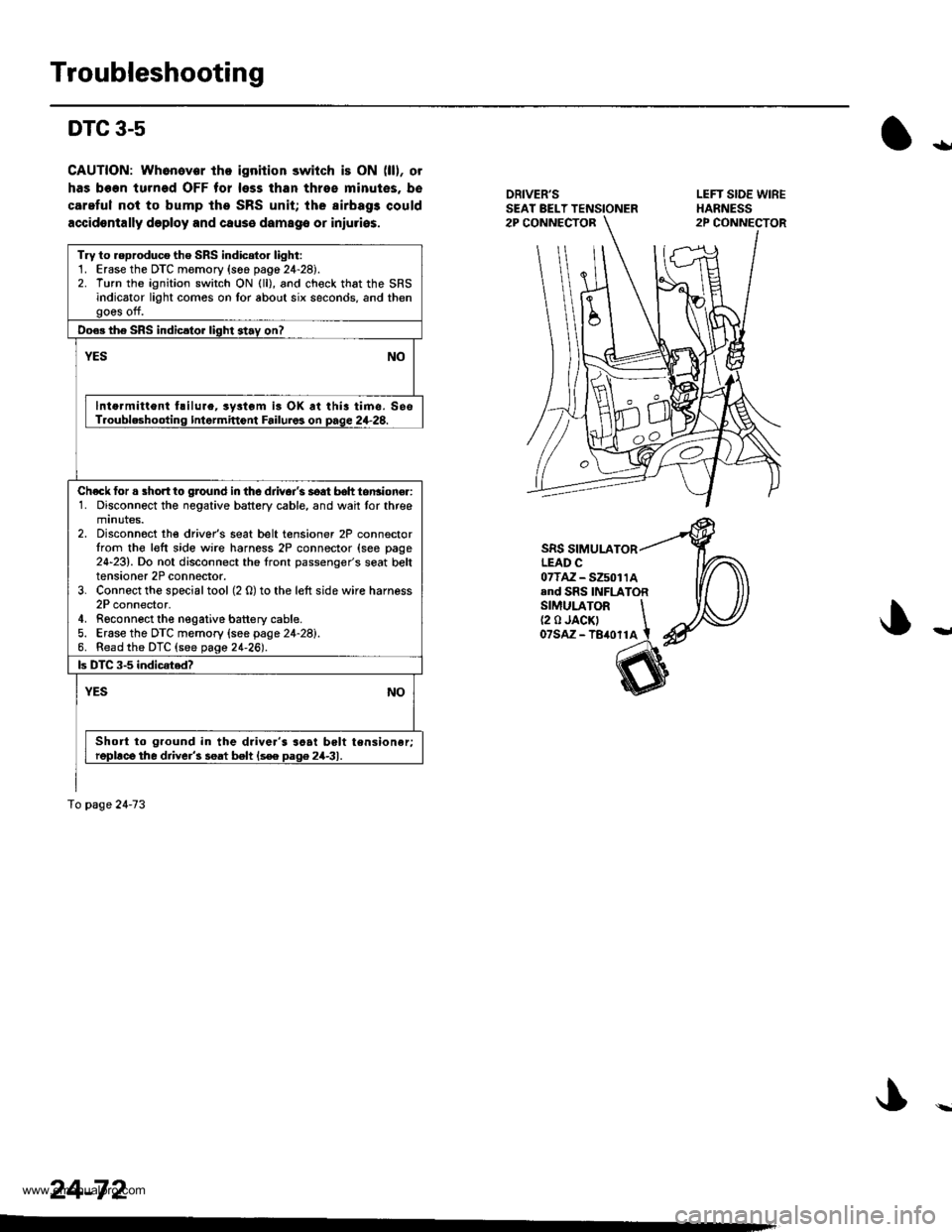
DRIVER'SSEAT BELT TENSIONER
SRS SIMULATORLEAD C07TAZ-S25011Aand SRS INFLATORSIMULATOR \(2 0 JACK' Iozsnz -teronl t
Try to reproduco the SRS indioto. light:1. Erase the DTC memory (s66 pag6 24-28).2. Turn the ignition switch ON (ll), and check that the SRSindicator light comos on Ior about six seconds, and thengoes off.
Do€. the SRS indicsto. light 3tav on?
YESNO
lnto.mitlont hilure, ryltom is OK at thia timc. SesT.oubleshootinq Intermittont Failuros on page 2+28.
Ch€ck for a short to ground in the djivoi's soat b6h tonsioner:1. Disconnect the negative battery cable, and wait tor threemtnutes.2. Disconnoct the driver's seat belt tensioner 2P connectorIrom the l€ft side wire harness 2P connector (see page24-23). Do not disconnect the front passenger's seat belttensioner 2P connector.3. Connect the special tool (2 0) to the left side wire harness2P connector,4. Rgconnect the negative battery cable.5. Erase the DTC memory (see page 24-28).6. Read the DTC (see page 21-26).
ls DTC 3-5 indicated?
YESNO
Short to ground in the driver's soai belt tensioner;repllce the driver'3 seat belt ls€e Daq6 24-31.
To page 2a-73
24-72
www.emanualpro.com
Page 1370 of 1395
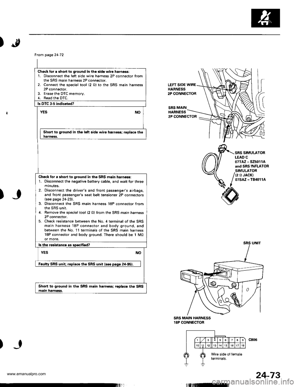
)
LEFT SIDE wlREHARNESS2P CONNECTOR
SRS MAINHARNESS
(
C
00
2P CONNECTOR
SRS SIMULATORLEAD C07TAZ - SZ5011Aand SRS INFLATORSIMULATOR
/ (2 o JACK)
/ 07sAz - TB4o11A
I
)
SRS MAIN HABNESS18P CONNECTOR
)
Frcm page24-12
Check lor . short to ground in lhe lido wire hrrnassi1. Disconnect the l€lt side wiro hamess 2P connector fromthe SRS main harness 2P connector.2. Connect the special tool (2 0) to the SRS main harness2P connoctor.3. Erase the DTC memory.4. Read the DTC.
Short to ground in the lolt side wi.e harno3s; .eplsce thehamer3.
Check for a short to ground in tho SRS main harna+t:1. Disconnect tho negative battery cable, and wait for threemtnutes.2. Disconnect the drive/s and front passenger's airbags,and front passenger's seat bolt tensioner 2P connectors(see page 24-231.3. Disconnect the SRS main harness l8P connector fromthe SRS unit.4. Remove the spacialtool {2 0) from the SRS main hamess2P connector,5. Check resistance between the No. 4 terminal of the SRSmain harness 18P connector and body ground, andbetween the No. ll terminals ofthe SRS main harness18P connector and body ground. There should be 1 M0or more.
Short to ground in the SRS m.in hrrnar3; roplaco tho SRSmein hamoSs.
24-73
www.emanualpro.com
Page 1376 of 1395
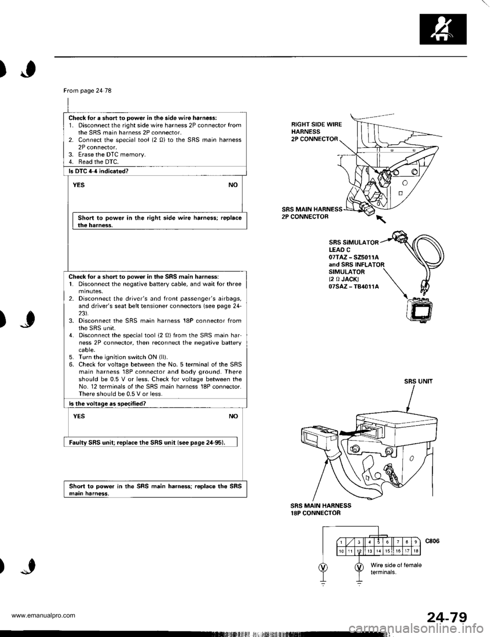
)
RIGHT SIDE WIREHARNESS2P CONNECTOR
SRS MAIN2P CONNECTOR
SBS SIMULATORLEAD C07TAZ - SZ5011Aand SRS INFLATORSIMULATOR \(2 0 JACK) \07sAz-T84011A \\
)J
)
@
SRS MAIN HARNESS18P CONNECTOR
Ftom page 24 78
Check for a short to power in the side wire harn6s:1. Disconnect the right side wire harness 2P connector fromthe SRS main harness 2P connector,2- Connect the special tool (2 0) to the SRS main harness2P connector.3. Erase the DTC memory.4. Read the DTC.
ls DTC 4-{ indicated?
YESNO
Short to power in the right side wire harness; replacethe harness.
Check tor a short to oow6r in the SRS main harness:1. Disconnect the negative battery cable, and wait for threemtnutes,2. Disconnect the driver's and front passenger's airbags,and driver's seat belt tensioner connectors (see page 24-23).3. Disconnect the SRS main harness 18P connector fromthe sRS unit.4. Disconnect the special tool i2 0) from the SRS main harness 2P connector, then reconnect the negative batterycaore.5. Turn the ignition switch ON (ll).
6. Check for voltage between the No. 5 terminal of the SRSmain harness 18P connector and body ground. Thereshould be 0.5 V or less. Check for voltage between theNo. 12 terminals of the SRS main harness 18P connector.There should be 0.5 V or less.
ls the voltage as specified?
NOYES
Faulty SRS unit; replace the SRS unit (see pase 24-95).
Short to power in the SRS main harness; replace the SRSmain harness.
24-79
www.emanualpro.com