connector a HONDA CR-V 1999 RD1-RD3 / 1.G Workshop Manual
[x] Cancel search | Manufacturer: HONDA, Model Year: 1999, Model line: CR-V, Model: HONDA CR-V 1999 RD1-RD3 / 1.GPages: 1395, PDF Size: 35.62 MB
Page 651 of 1395
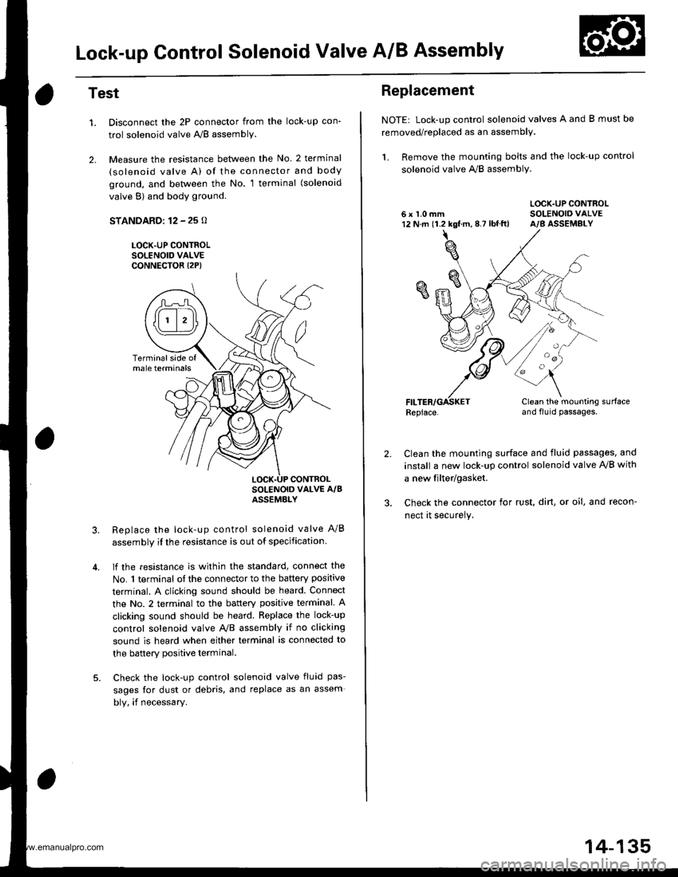
Lock-up Control Solenoid Valve A/B Assembly
Test
1.
2.
Disconnect the 2P connector from the lock-up con'
trol solenoid valve A'lB assembly.
Measure the resistance between the No. 2 terminal
(solenoid valve A) of the connector and body
ground. and bet\iveen the No. 1 terminal (solenoid
valve B) and body ground.
STANDARD: 12 - 25 o
LOCK-UP CONTROLSOLENOID VALVECONNECTOR I2P)
Replace the lock-up control solenoid valve A/B
assembly if the resistance is out of specification
lf the resistance is within the standard, connect the
No. 1 terminal of the connector to the battery positive
terminal. A clicking sound should be heard Connect
the No. 2 terminal to the battery positive terminal. A
clicking sound should be heard. Replace the lock-up
control solenoid valve Ay'B assembly if no clicking
sound is heard when either terminal is connected to
the banerv Dositive terminal.
Check the lock-up control solenoid valve fluid pas-
sages for dust or debris, and replace as an assem
bly, if necessary.
Terminalside ofmale terminals
LOCK.UP CONTROL
Replacement
NOTE: Lock-up control solenoid valves A and B must be
removed/replaced as an assembly.
1. Remove the mounting bolts and the lock-up control
solenoid valve A,,/B assembly.
LOCK.UP CONTROL6 x 1.0 mm SOLENOIO VALVE12 N.m 11.2 kgf.m,8.7 lbf.ft) A/B ASSEMBLY
Replace.Clean the mounting surfaceand flu id passages.
2.Clean the mounting surface and fluid passages, and
install a new lock-up control solenoid valve IVB with
a new filter/gasket.
Check the connector for rust, dirt, or oi!, and recon-
nect it securely.
oa
14-135
www.emanualpro.com
Page 652 of 1395
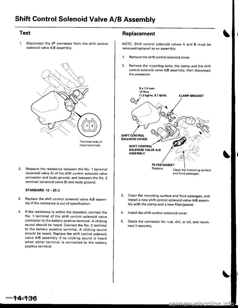
Shift Control Solenoid Valve A/B Assembly
Test
'1. Disconnect the 2P connector from
solenoid valve Ay'B assembly.
the shift control
Terminalsade ofmale terminals
Measure the resistance between the No. 1 terminal(solenoid valve A) of the shift control solenoid valve
connector and body ground, and between the No. 2terminal (solenoid valve B) and body ground.
STANDARD: 12 - 25 O
Replace the shift control solenoid valve A,/B assem-bly if the resistance is out of specification.
lf the resistance is within the standard. connect theNo, I terminal of the shift control solenoid valveconnector to the battery positive terminal. A clickingsound should be heard. Connect the No. 2 terminalto the battery positive te.minal. A clicking soundshould be heard. Replace the shift control solenoidvalve A/B assembly if no clicking sound is heardwhen either terminal is connected to the battervpositive terminal.
14-136
Replacement
NOTE: Shift control solenoid valves A and B must beremoved/replaced as an assembly.
1. Remove the shift control solenoid cover.
2. Remove the mounting bolts, the clamp and the shiftcontrol solenoid valve Ay'B assembly, then disconnect
the connector.
6x1.0mm12 N.m{1.2 k9 .m,8.7 lbtft}CLAMP ARACKET
FILTER/GASKETReplace.Clean the mounling surfaceand fluid passages.
Clean the mounting surface and fluid passages. andinstall a new shift control solenoid valve Ay'B assem-bly with the clamp and a new filter/gasket.
Install the shift control solenoid cover.
Check the connector for rust, dirt. or oil, and recon-nect it securely.
w
SHIFT CONTROLSoLENO|O COVEn
SHIFT CONTROLSOLENOID VALVE A/BASSEMBLY
\--
qK
-!t'">,,
www.emanualpro.com
Page 653 of 1395
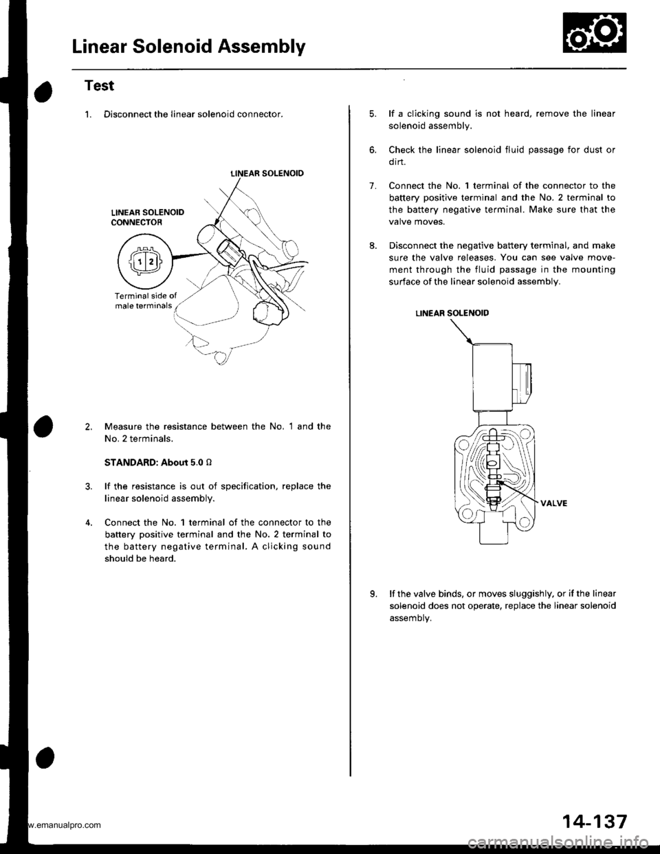
Linear Solenoid Assembly
Test
1. Disconnect the linear solenoid connector.
LINEAR SOLENOIO
Measure the resistance between the No, 1 and the
No. 2 terminals.
STANDARD: About 5.0 o
lf the resistance is out of specification, replace the
linear solenoid assembly.
Connect the No. 1 terminal of the connector to the
battery positive terminal and the No. 2 terminal to
the battery negative terminal, A clicking sound
should be heard.
1.
lf a clicking sound is not heard, remove the linear
solenoid assembly.
Check the linear solenoid fluid passage for dust or
orn.
Connect the No. 1 terminal of the connector to the
battery positive terminal and the No. 2 te.minal to
the battery negative terminal. Make sure that the
valve moves.
Disconnect the negative battery terminal. and make
sure the valve releases. You can see valve move-
ment through the fluid passage in the mounting
surface of the linear solenoid assembly.
LINEAR SOLENOID
VALVE
lf the valve binds, or moves sluggishly. or if the linear
solenoid does not operate, replace the linear solenoid
assemotv.
K
14-137
www.emanualpro.com
Page 654 of 1395
Mai nshaft /Cou ntershaft
Linear Solenoid AssemblySpeed Sensors
Replacement
'1. Remove the mounting bolts and the linear solenoid
assemblY.
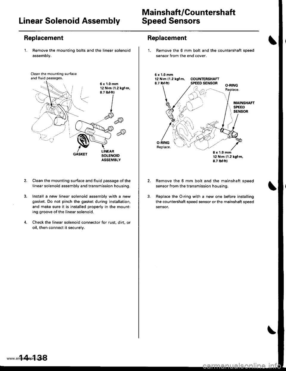
Clean the mounting surfaceand fluid passages.
6x1.0mm12 N.m (1.2 kg{.m.8.7 tbtftl
@
@
GASKET
Clean the mounting surface and fluid passage of the
linear solenoid assembly and transmission housing.
Install a new linear solenoid assemblv with a new
gasket. Do not pinch the gasket during installation,
and make sure it is installed properly in the mount-
ing groove of the linear solenoid.
Check the linear solenoid connector for rust. dirt, or
oil, then connect it securelv.
14-138
Replacement
1. Remove the 6 mm bolt and the countershaft sDeed
sensor from the end cover.
\
5x1.0mm12 N.m 11.2 kgf.m, COUNTERSHAFT8.7 rbf.frl SPEED SENSOR
O.RINGReplace.
12 N'm 11.2 kgl.m,8.7 tbf.ftl
Remove the 6 mm bolt and the mainshaft speed
sensor from the transmission housing.
Replace the O-ring with a new one before installing
the countershaft speed sensor or the mainshaft speed
sensor,
6x1.0mm
www.emanualpro.com
Page 655 of 1395
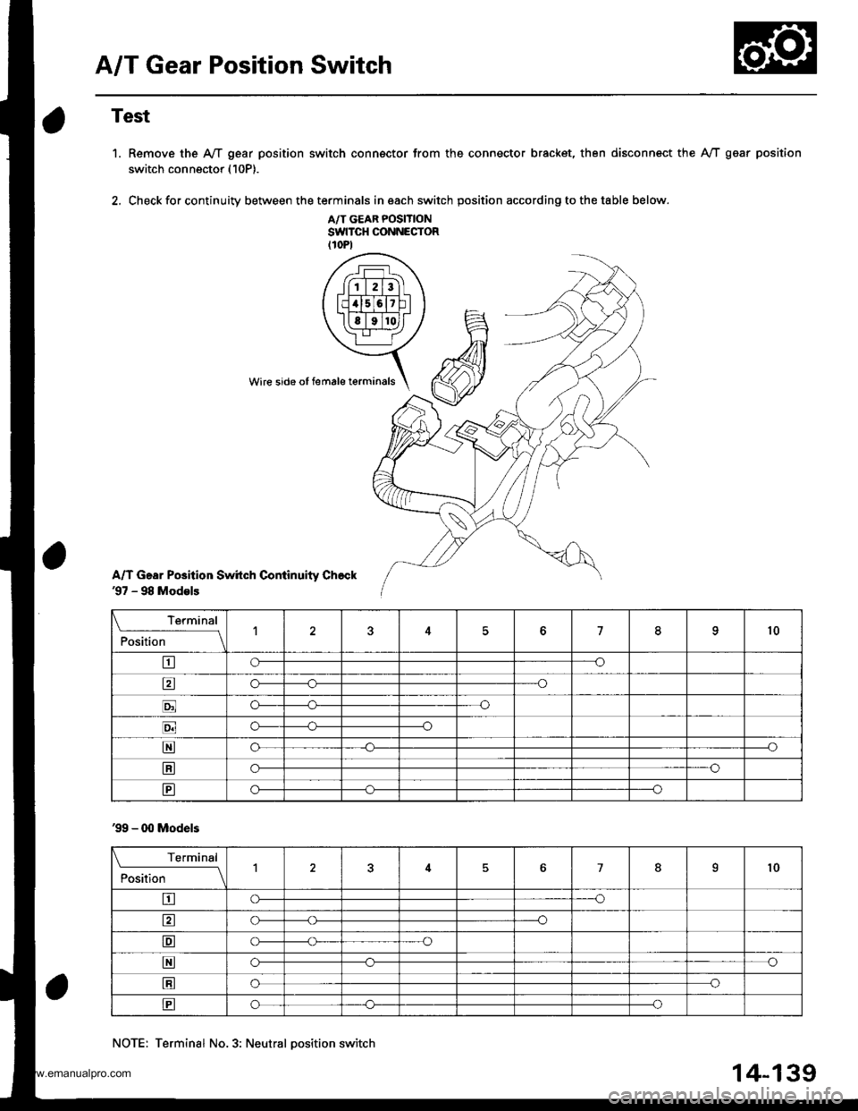
A/T Gear Position Switch
Test
1. Remove the A,/T gear position switch connsctor from the connector bracket, then disconnect the IVT gear position
switch connector (10P).
2. Check for continuity between the terminals in each switch position according to the table below.
A/T GEAR POSITIONSWITCH CONNECTOR(10P1
A/T Gear PGition Swhch Coniinuity Ch6ck'97 - 98 Models
Wire side oI female terminals
\_-__l"'ry1
Position
'l76o10
tro--o
tro------o
t!l!lo-----o
Eo_----o
Eo_-----o
Eo----o
Eo-----o
'99 - O0 Models
\______lg,-r4
Position1467.'l0
tro----o
trc\----o
Eo-----o
Eo--o
Eoo
Eo_----c
NOTE: Terminal No.3: Neutral oosition switch
14-139
www.emanualpro.com
Page 656 of 1395
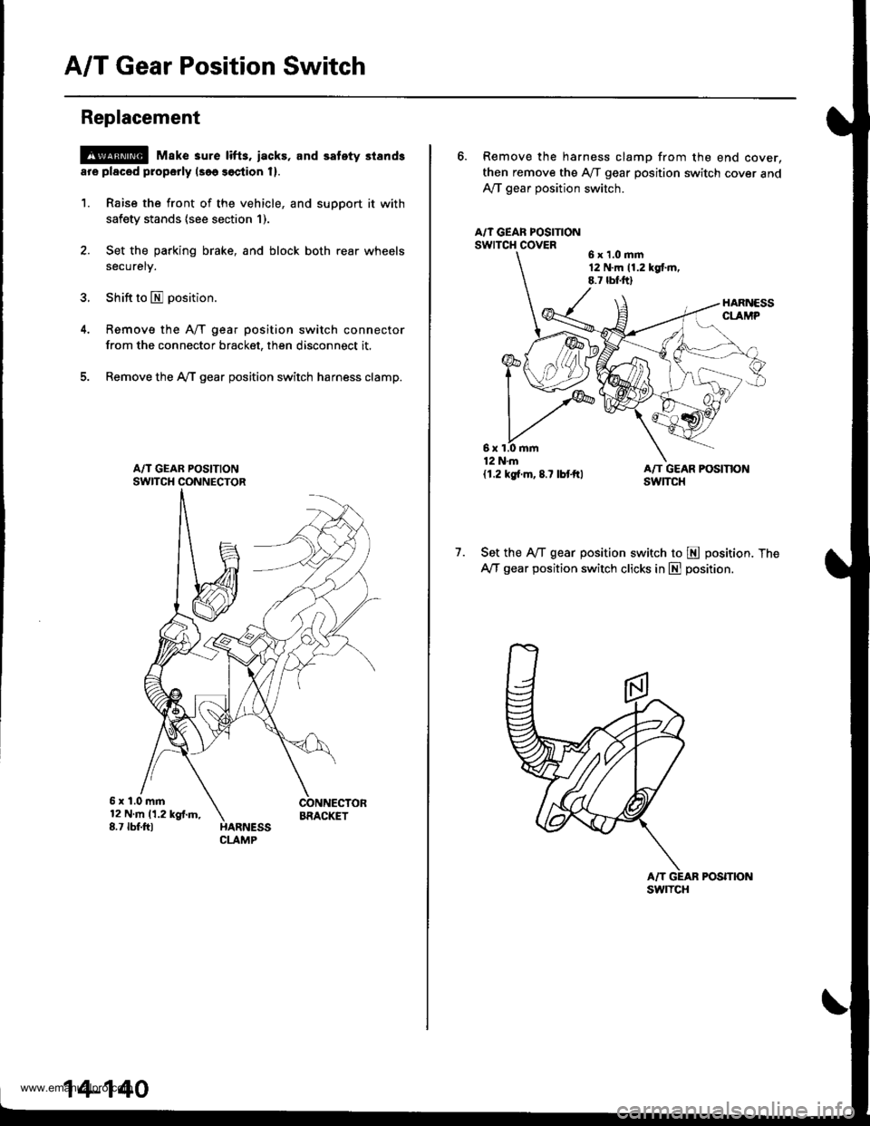
A/T Gear Position Switch
Replacement
@ Make 3ure lifts, iacks, and safety stands
ar€ placod properly lsoo soction 1).
1. Raise the front of the vehicle, and support it with
safety stands (see section 1).
2. Set the parking brake, and block both rear wheels
securely.
3. Shift to E position.
Remove the A/T gear position switch connector
from the connector bracket, then disconnect it.
Remove the AfI gear position switch harness clamp.
5x1.0mm12Nm11.2kgf.m,8.7 tbf.fttBRACIGT
14-140
6. Remove the harness clamp from the end cover,
then remove the Aff gear position switch cover and
Ay'T gear position switch.
A/T GEAF POSITIONswrTcH covER6x1.0mm12 N.m 11.2 kgt m.8.7 lbf.ftl
1.Set the IVT gear position switch to E position. The
AfI gear position switch clicks in E position.
POSmON
6x1.0mm12 N.m
{1.2 kg{.m,8.7 lbtftl
swlTcH
www.emanualpro.com
Page 657 of 1395
![HONDA CR-V 1999 RD1-RD3 / 1.G Workshop Manual
8. Set the control shaft to E] position. then install the
A,/T gear position switch on it.
CONTROL SHAFT
Install the AyT gear position switch cover and har-
ness clamp on the end cover.
Connect the HONDA CR-V 1999 RD1-RD3 / 1.G Workshop Manual
8. Set the control shaft to E] position. then install the
A,/T gear position switch on it.
CONTROL SHAFT
Install the AyT gear position switch cover and har-
ness clamp on the end cover.
Connect the](/img/13/5778/w960_5778-656.png)
8. Set the control shaft to E] position. then install the
A,/T gear position switch on it.
CONTROL SHAFT
Install the Ay'T gear position switch cover and har-
ness clamp on the end cover.
Connect the A,/T gear position switch connector.
then install it on the connector bracket.
Turn the ignition switch ON (ll). Move the shift lever
through all gears, and check the AfI gesr position
switch synchronization with the A/T gear position
indicator.
9.
10.
11.
A/TGEARPOSMON A/T GEAR POSITIONINDICATOR INDICATOR'99 - 00 MODELS '�97 - 98 MOOELS
12, Start the engine. Move the shift lever through all
gears. and verify the following:
. The shift lever cannot be moved to E] position
from E position unless the shift lever is pulled.
. The engine will not start in any position other
than E or E.. The back-up lights come on when the shift lever
is in El position.
14-141
www.emanualpro.com
Page 658 of 1395

A/T Gear Position Indicator
1.
f nput Test -'97 - 98 Models
Remove the gauge assembly from the dashboard (see section 20). and disconnect the 14P connector from the gauge
assemblv (see section 23),
Inspect the connector and socket terminals to be sure they are all making good contact.
. lf the terminals are bent, loose, or corroded, repairthem as necessary, and recheck the system.. lf the terminals look OK, make the following input tests at the 14P connector.- lf I test indicates a problem, find and correct the cause, then recheck the system.- lf all the input tests prove OK, but the indicator is faulty. replace the printed circuit board,
GAUGE ASSEMBLY 14P CONNECTOR
Wire side of female terminals
CavityWirs
ColorTest ConditionTest: Desir€d ResultPossible Cause
{lf rosult is not obtainod)
YEL
lgnition switch ON (ll)Check for voltage to ground:
There should be battery voltage,
. Blown No. 25 (7.5 A) fuse in the
under-dash fuse/relay box. An open in the wire
RE D/BLKCombination light
switch ON and dash
lights brightness con-
trol dial on full bright
Check for voltage between No. 2
and No. 3 terminals;
There should be battery voltage.
Blown No. 47 (7.5 A) fuse in the
under-dash fuse/relay box
Faulty combination Iight switch
Faulty dash iight brightness
controller
An open in the wire
RED
4BLUShift lever in ECheck for continuity to ground:
There should be continuity.
NOTE: There should be no continu-
ity in any other shift lever position.
' Faulty Ay'T gear position switch. An open in the wireBRNShift lever in E
7YELShift lever in @
8BLKUnder all conditionsCheck for continuity to ground:
There should be continuity
. Poor ground {G401). An open in the wire
9GRN/BLK
lgnition switch ON {ll)
and shift lever in any
position except E
Check for voltage to ground:
There should be battery voltage
for two seconds after the ignition
switch is turned ON {ll), and less
than 1 V two seconds later,
' Faulty PCM. An open in the wire
10GRNShift lever in ECheck for continuity to ground:
There should be continuity.
NOTE: There should be no conti-
nuity in any other shift lever posi-
UOn.
. Faulty A,ff gear position switch. An open in the wire1'lREDShift lever in @
12WHTShift lever in E
BLVBLU
Shift lever in ENOTE: Do not push
the brake pedal.
14LT GRN
lgnition switch ON { ll)
and shift lever in any
position except E and
E
Check for voltage to ground:
There should be about 5 V.
. Faulty PCM. An open in the wire
14-142
www.emanualpro.com
Page 659 of 1395

L
Input Test -'99 - 00 Models
Remove the gauge assembly from the dashboard {see section 20), and disconnect the 14P connector from the gauge
assembly (see section 23).
Inspect the connector and socket terminals to be sure they are all making good contact.
a lf the terminals are bent. loose, or corroded. repair them as necessary. and recheck the system.
. lf the terminals look OK, make the following input tests at the 14P connector.- lf a test indicates a problem, find and correct the cause, then recheck the system.- lf all the input tests prove OK, but the indicator is faulty, replace the printed circuit board.
GAUGE ASSEMBLY 14P CONNECTOR
Wire side of female terminals
CavityWire
ColorTest ConditionTest: Desired ResuhPossible Caus6
{lf resutt is not obtainod)
1YEL
lgnition switch ON (ll)Check for voltage to ground:
There should be battery voltage.
. Blown No.25 (7.5 A) fuse in the
under-dash fuse/relay box. An open in the wire
2RE D/BLK
Combination light
switch ON and dash
lights brightness con-
trol dial on full bright
Check for voltage between No. 2
and No.3 terminals:
There should be battery voltage.
Blown No. 47 {7.5 A) fuse in the
under-dash fuse/relay box
Faulty combination light switch
Faulty dash light brightness
controller
An open in the wire
5RED
BRNShift lever in ECheck for continuity to ground:
There should be continuity.
NOTE: There should be no continu-
ity in any other shift lever position.
. Faulty A/T gear position switch. An open in the wire7YELShift lever in E
'10BLUShift lever in E
LT BLU
lgnition switch ON (ll),
shift lever in E. and
Over-Drive is OFF bypressing O/D switch.
Check for continuity to ground:
There should be continuity.
Faulty O/D switch
Faulty A/T gear position switch
Faulty PCM
An open in the wire
8BLKUnder all conditionsCheck for continuity to ground:
There should be continuity
. Poor ground (G401)
. An open in the wire
9a:FI\|/Et| ta
lgnition switch ON (ll)
and shift lever in any
position except E
Check for voltage to groundl
There should be battery voltage
for two seconds after the ignition
switch is turned ON (ll). and less
than 1 V two seconds later.
. Faulty PCM. An open in the wire
11REDShift lever in SCheck for continuity to ground:
There should be continuity.
NOTE: There should be no conti-
nuity in any other shift lever posi-
Iton.
. Faulty A/T gear position switch. An open in the wire12WHTShift lever in E
BLI(BLU
Shift lever in ENOTE: Do not push
the brake pedal.
14LT GRN
lgnition switch ON (ll)
and shift lever in any
position except E and
E
Check for voltage to groundl
There should be about 5 V,
. Faulty PCM. An open in the wire
14-143
www.emanualpro.com
Page 660 of 1395
Interlock System
Interlock Control Unit Input Test
SRS components are located in this area. Review the SRS component locations, precautions, and procedures in the SRS
section (24) before performing repairs or service.
'1. Remove the instrument panel lower cover (see section 20).
2. Disconnect the 8P connector from the interlock control unit.
3. Inspect the connector and connector terminals to be sure they are all making good contact.
. lf the terminals are bent, loose, or corroded, repair them as necessary, and recheck the system
. lf the terminals look OK, make the following input tests at the connector.
- lf a test indicates a problem, find and correct the cause, then recheck the system
- lf all the input tests prove OK, substitute a known-good control unit, and recheck the system. lf the check is OK,
the control unit must be faulty; replace it.
NOTE: lf the shift lock solenoid clicks when the ign ition switch is tu rned ON (ll) while pressing the brake pedal withthe
shift lever in E position, the shift lock system is OK. lf the shift lever cannot be shifted from E position. test the A/T
gear position switch.
14-144
www.emanualpro.com