Drive HONDA CR-V 1999 RD1-RD3 / 1.G Workshop Manual
[x] Cancel search | Manufacturer: HONDA, Model Year: 1999, Model line: CR-V, Model: HONDA CR-V 1999 RD1-RD3 / 1.GPages: 1395, PDF Size: 35.62 MB
Page 1241 of 1395
Adjustment
Bstore adiusting the headlights:
. Park the vehicle on level ground
. Make sure the fuel tank is tull
. The driver or someone who weighs the same should
sit in the driver's seat.
. Load the trunk with the items you usually carry'
. Push down on the front and rear bumpers several
times to make sure the vehicle is sitting normally'
CAUTION: Halogen headlights become very hot in use;
do not touch them or the atiaching hardware immedi-
ately after they have been turned off.
1. ODen the hood.
2. Remove the left inner fender {see section 20).
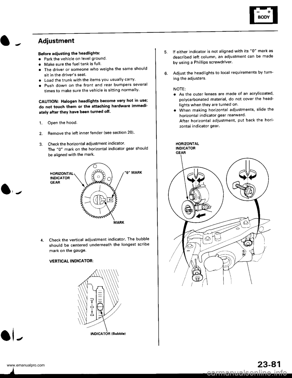
3. Checkthe horizontal adjustment indicator.
The "0" mark on the horizontal indicator gear should
be aligned with the mark.
"0" MARK
Check the vertical adjustment indicator. The bubble
should be centered underneath the longest scribe
mark on the gauge.
VERTICAL INDICATOR:
ol-
)
5.lf either indicator is not aligned with its "0" mark as
described left column, an adjustment can be made
by using a Phillips screwdriver.
Adjust the headlights to local requirements by turn-
ing the adjusters.
NOTE:
. As the outer lenses are made of an acrylicoated,
polycarbonated material, do not cover the head-
lights when they are turned on
. When making horizontal adiustments, slide the
horizontal indicator gear rearward.
After horizontal adjustment, put back the hori-
zontal indicator gear.
HORIZONTALINDICATORGEAR
23-A1
www.emanualpro.com
Page 1247 of 1395
![HONDA CR-V 1999 RD1-RD3 / 1.G Workshop Manual
Turn Signal Switch Test
1.
4.
Remove the drivers dashboard lower cover and the
knee bolster (see section 20).
Remove the steering column covers {see section
17]-.
Disconnect the 4P and 7P connectors HONDA CR-V 1999 RD1-RD3 / 1.G Workshop Manual
Turn Signal Switch Test
1.
4.
Remove the drivers dashboard lower cover and the
knee bolster (see section 20).
Remove the steering column covers {see section
17]-.
Disconnect the 4P and 7P connectors](/img/13/5778/w960_5778-1246.png)
Turn Signal Switch Test
1.
4.
Remove the driver's dashboard lower cover and the
knee bolster (see section 20).
Remove the steering column covers {see section
17]-.
Disconnect the 4P and 7P connectors from the
switch.
Remove the screws, and slide the switch toward the
driver's door.
Check for continuity between the terminals in each
switch position according to the table.
Position
Terminal12
RIGHTo-
Neutral
LEFTo---o
q
tl-
swtTcH
Hazard Warning Switch Test
1. Remove the center panel {see section 20).
2. Remove the two screws, then remove the switch
from the center air vent.
HAZARD
Check for continuitv between the terminals in each
switch position according to the table.
Terminal
t**--\
2357810
OFF(9U(_)
ONo@oooo
lNol us€d)
23-87
www.emanualpro.com
Page 1249 of 1395
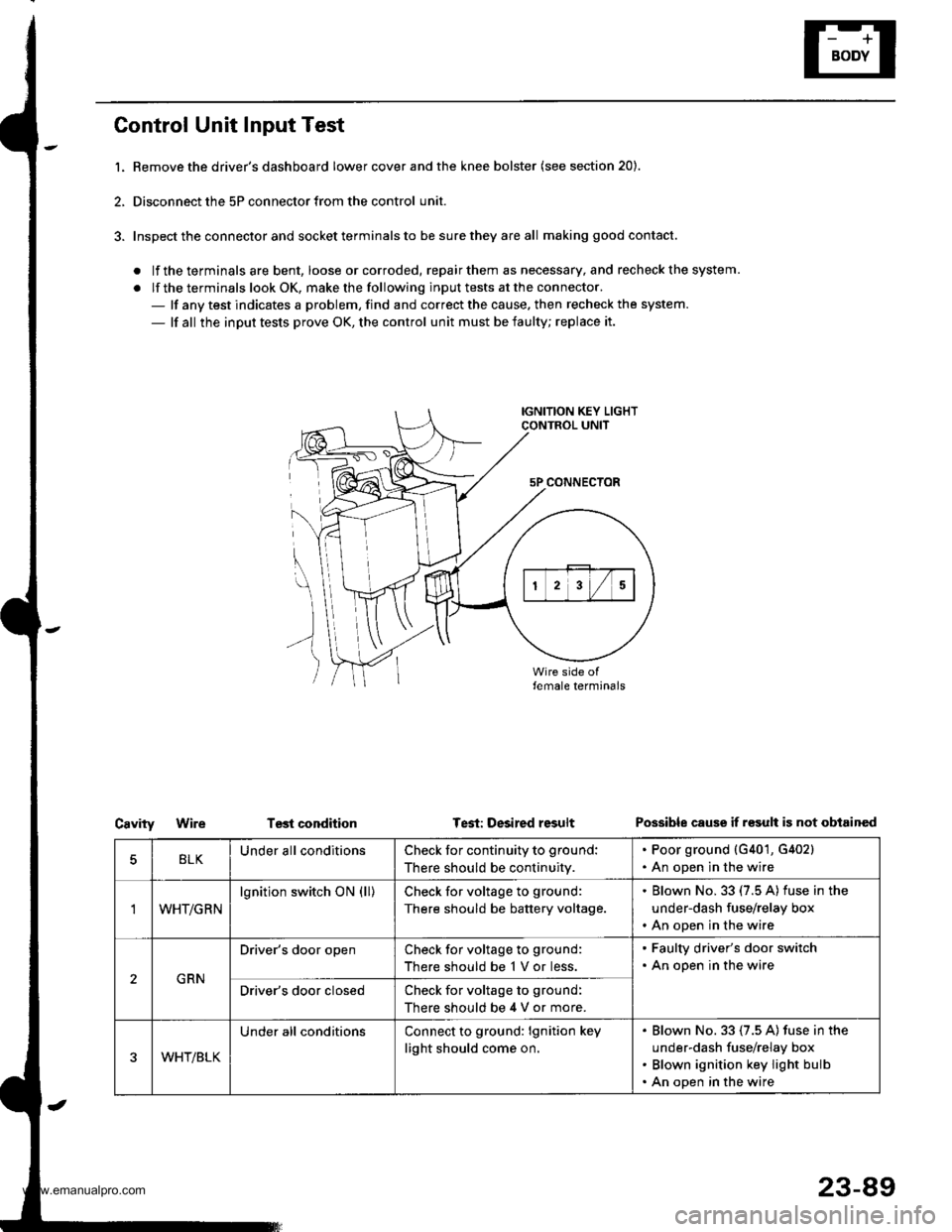
Control Unit Input Test
l. Bemove the driver's dashboard lower cover and the knee bolster (see section 20).
2, Disconnect the 5P connector from the control unit.
3. Inspect the connector and socket terminals to be sure they are all making good contact.
. lf the terminals are bent, loose orcorroded, repairthem as necessary, and recheck the system.
. lf the terminals look OK, make the following input tests at the connector.- lf any test indicates a problem, find and correct the cause. then recheck the system.
- lf all the input tests prove OK, the control unit must be faulty; replace it.
IGNITION KEY LIGHTCONTROL UNIT
5P CONNECTOR
\
))
Test conditionCavityWireTest: Desired resultPossible cause if r€sult is not obtained
BLKUnder all conditionsCheck for continuity to ground:
There should be continuity.
. Poor ground {G401, G402}. An open in the wire
'IWHT/GRN
lgnition switch ON (ll)Check for voltage to ground:
There should be battery voltage.
. Blown No. 33 (7.5 A) fuse in the
under-dash fuse/relay box. An open in the wire
GRN
Driver's door openCheck for voltage to ground:
There should be 1 V or less.
. Faulty driver's door switch. An open in the wire
Driver's door closedCheck for voltage to ground:
There should be 4 V or more.
WHT/BLK
Under all conditionsConnect to ground: lgnition key
light should come on.
Blown No. 33 (7.5 A) fuse in the
under-dash fuse/relay box
Blown ignition key light bulb
An open in the wire
23-89
www.emanualpro.com
Page 1252 of 1395
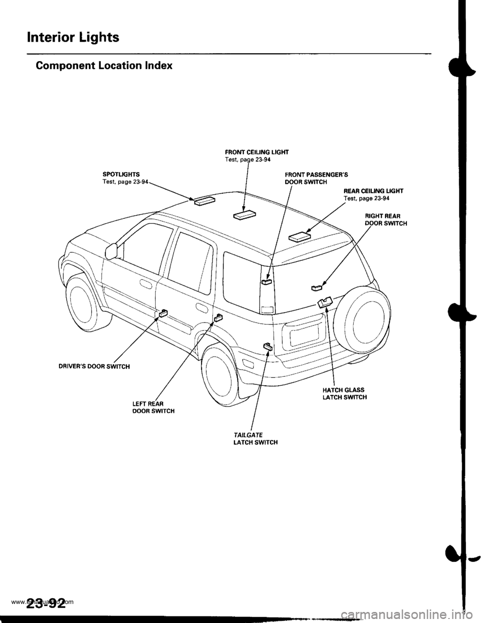
Interior Lights
Component Location Index
SPOTLIGHTSTest, page
DRIVER'S DOOR SWITCH
LEFT REARoooR swtTcH
FRONT CEILING LIGHTTest, page 23-94
FRONT PASSENGER'SDOOR SWITCH
REAR CCILING LIGI{TTest, page 23-94
RIGHT REARswtTcH
HATCH GLASSLATCH SWITCH
TAILGATELATCH SwlTCH
23-92
www.emanualpro.com
Page 1266 of 1395
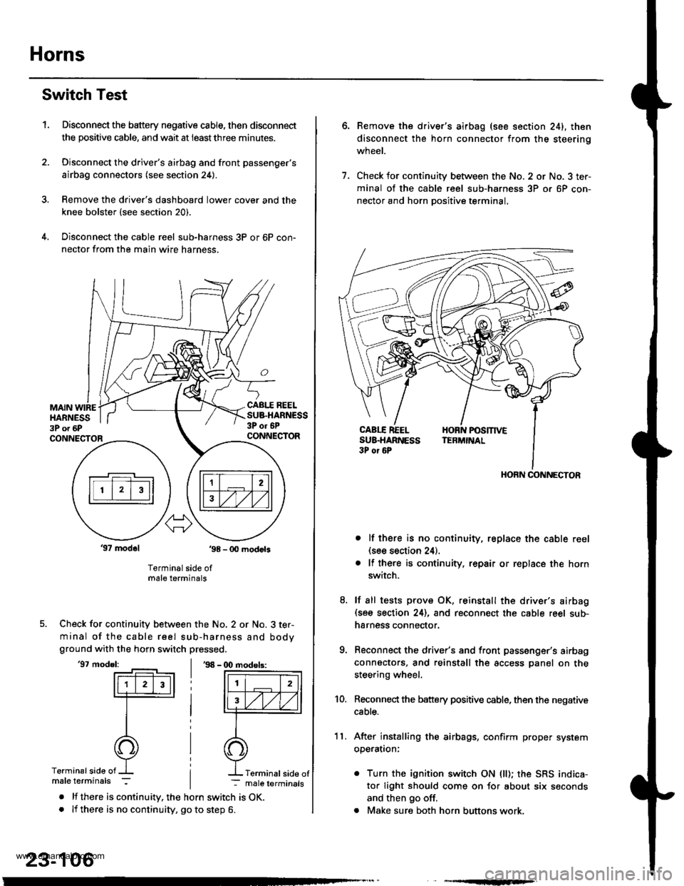
Horns
Switch Test
Disconnect the battery negative cable, then disconnect
the positive cable, and wait at ieastthree minutes.
Disconnect the driver's airbag and front passenger's
airbag connectors (see section 24).
Remove the drive.'s dashboard lower cover and the
knee bolster (see section 20).
Disconnect the cable reel sub-harness 3P or 6P con-
nector from the main wire harness.
1.
MAIN WIREHARNESS3P o. 6P
CABI.I REELSUB.HARNESS3P or 6PCONNECTORCONNECTOR
37 modol ,98 - 0O modots
Terminal side ofmale terminals
Check for continuity between the No. 2 or No. 3 ter-
minal of the cable reel sub-harness and bodyground with the horn switch pressed.
'97 model:'98 - (X) modols:
Terminalside of
. lf there is continuity. the horn switch is OK.. lf there is no continuity, go to step 6.
23-106
Terminal side of
6.Remove the driver's airbag (see section 241, then
disconnect the horn connector from the steerinq
wneet.
Check for continuity between the No. 2 or No. 3 ter-
minal of the cable reel sub-harness 3P or 6P con-
nector and horn Dositive terminal.
lf there is no continuity, replace the cable reel(see section 24).
lf there is continuity. repair or replace the horn
switch.
lf sll tests prove OK, reinstall the driver's airbag(see section 24), and reconnect the cable reel sub-
harness connector.
Reconnect the driver's and front passenger's airbag
connectors, and reinstall the access panel on the
steering wheel.
Reconnect the battery positive cable, then the negative
cable.
After installing the airbags, confirm proper system
operatron:
. Turn the ignition switch ON (ll); the SRS indica-
tor light should come on for about six seconds
and then go off.
. Make sure both horn buttons work.
7.
11.
8.
9.
10.
HORN CONNECTOR
www.emanualpro.com
Page 1278 of 1395
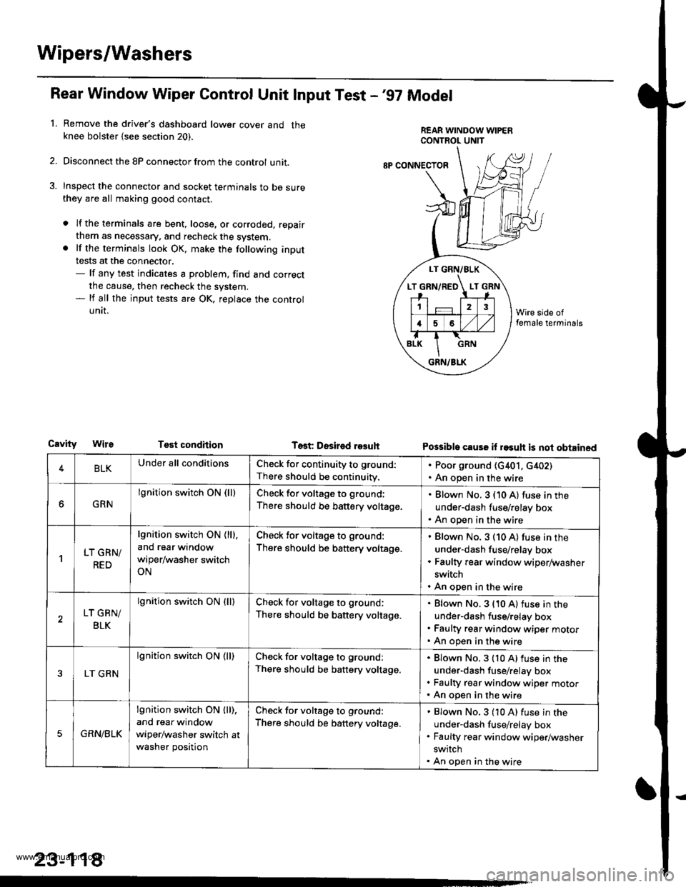
Wipers/Washers
Rear Window Wiper Gontrol Unit lnput Test -'97 Model
Remove the driver's dashboard lower cover and theknee bolster {see section 20).
Disconnect the 8P connector from the control unit.
Inspect the connector and socket terminals to be surethey are all making good contact.
a lf the terminals are bent, loose, or corroded, repair
them as necessary. and recheck the system.. lf the terminals look OK, make the following input
tests at the connector.- lf any test indicates a problem, find and correct
the cause, then recheck the system.- lf all the input tests are OK, replace the control
UNII.
1.
LT GRN/BLK
T GRN/RED LT
12
16
GRN/BLK
8P CONNECTOF
CavityTest condhion Test Desir€d r93uhPossible cause il rasuh is not obtained
4BLKUnder all conditionsCheck for continuity to ground:
There should be continuity.
. Poor ground (G401, c402). An open in the wire
GRN
lgnition switch ON (lllCheck for voltage to ground;
There should be battery voltage.
Blown No. 3 (10 A) fuse in the
under-dash fuse/relay box
An open in the wire
'lLT GRN/
RED
lgnition switch ON ( ll),
and rear window
wiper/washer switch
ON
Check for voltage to ground:
There should be battery voltage.
Blown No. 3 (10 A) fuse in the
under-dash fuse/relay box
Faulty rear window wiper/washer
switch
An open in the wire
LT GRN/
BLK
lgnition switch ON (lllCheck for voltage to ground;
There should be battery voltage.
Blown No. 3 {10 A) fuse in the
under-dash fuse/relay box
Faulty rear window wiper motor
An open in the wire
LT GRN
lgnition switch ON (ll)Check for voltage to ground:
There should be battery voltage.
Blown No.3 {10 A)fuse in the
under-dash fuse/relay box
Faulty rgar window wiper motorAn open in the wire
5GRN/BLK
lgnition switch ON lll),
and rear window
wiper/washer switch at
washer position
Check for voltage to ground:
There should be battery voltage.
Blown No.3 (10 A) fuse in the
under-dash fuse/relay box
Faulty rear window wiper/washer
switch
An open in the wire
23-118
www.emanualpro.com
Page 1279 of 1395
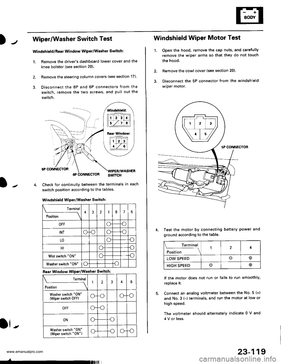
Wiper/Washer Switch Test
Windshield/ReEr Window Wiper/Washer Switch:
1. Remove the driver's dashboard lower cover and the
knee bolster (see section 20).
2. Remove the steering column covers {see section 17)
3. Disconnect the 8P and 6P connectors from the
switch, remove the two screws, and pull out the
switch.
J-
lind3hi.ld:
tilt-rltl
IEZIA
Raar Window:
11 2 3
I t-7 al
ll -
Check for continuity betlveen the termlnals in each
switch position according to the tables.
Windshield Wiper/Washer Switch:
Terminal
P*t-
---__\432175
OFFoo
INToooo
LOoo
HIoo
Mist swhch "0N"oo
Washer switch "0N"oo
Rear Window Wipsr/Washer Switch
Teminal
ti'"
---\12346
Washer switch '0N'
(wiper switch oFFlG-oG-o
OFFG-o
ONGo
Washer switch "ON'
(Wiper switch "0N"1G-oG-o
-rmxft
23-119
1.
Windshield Wiper Motor Test
Open the hood, remove the cap nuts, and caretully
remove the wiper arms so that they do not touch
the hood.
Remove the cowl cover (see section 201.
Disconnect the 5P connector trom the windshield
wiper motor.
Test the motor by connecting battery power and
ground according to the table.
lf the motor does not tun or fails to run smoothly,
replace it.
Connect an analog voltmeter between the No. 5 (+)
and No. 3 (-) terminals, and run the motor at low or
high speed.
The voltmeter should alternately indicate 0 V 8nd
4 V or less.
Terminal
;fi;"
-l4
LOW SPEED@
HIGH SPEED@
www.emanualpro.com
Page 1283 of 1395
![HONDA CR-V 1999 RD1-RD3 / 1.G Workshop Manual
Power Door Locks
Component Location lndex
DRIVERS DOOR L(rcK SWITCHTest, page 23-129
TRANSMITTERTest, page 23-130Cod6 Input Procedure,page 23-131
LOCK BUTTON
HATCH GLASS BUTTON
PA rc AUTTO]IIRIGT{T HONDA CR-V 1999 RD1-RD3 / 1.G Workshop Manual
Power Door Locks
Component Location lndex
DRIVERS DOOR L(rcK SWITCHTest, page 23-129
TRANSMITTERTest, page 23-130Cod6 Input Procedure,page 23-131
LOCK BUTTON
HATCH GLASS BUTTON
PA rc AUTTO]IIRIGT{T](/img/13/5778/w960_5778-1282.png)
Power Door Locks
Component Location lndex
DRIVER'S DOOR L(rcK SWITCHTest, page 23-129
TRANSMITTERTest, page 23-130Cod6 Input Procedure,page 23-131
LOCK BUTTON
HATCH GLASS BUTTON
PA rc AUTTO]IIRIGT{T REAR DOOR LOCKACTUATORTest, page 23-129Replacement,section 20
HATCH GLASS OPENER SOLENOIOfesl, page 23-122Replacem€nt. pago 23-122
FRONT PASSENGER'SDOOR LOCK ACTUATORTest, page 23-129R6Dlacement, soction 20
LEFT BEAR DOOR LOCKACTUATOBTesr, page 23-129Beplacement, section 20
. DRIVEB'S DOOR LOCKKNOB SW|TCHTesr, pag6 23-128. DRIVER'S DOOR LOCKACTUATORT6st, psge 23-128
-
23-123
www.emanualpro.com
Page 1284 of 1395
![HONDA CR-V 1999 RD1-RD3 / 1.G Workshop Manual
Power Door Locks
UNDER.HOOD FUSE/FELAY BOX
Circuit Diagram (With Keyless Entry System)
GN TION SW TCHUNDER DASHFUSE/RELAY BOXEATTEFY
@*n
WHT/GFN
8
ITEYLES--lI TRANSMIT]ER ILr--------
. PASSENGENS DO HONDA CR-V 1999 RD1-RD3 / 1.G Workshop Manual
Power Door Locks
UNDER.HOOD FUSE/FELAY BOX
Circuit Diagram (With Keyless Entry System)
GN TION SW TCHUNDER DASHFUSE/RELAY BOXEATTEFY
@*n
WHT/GFN
8
ITEYLES--lI TRANSMIT]ER ILr--------
. PASSENGENS DO](/img/13/5778/w960_5778-1283.png)
Power Door Locks
UNDER.HOOD FUSE/FELAY BOX
Circuit Diagram (With Keyless Entry System)
GN TION SW TCHUNDER DASHFUSE/RELAY BOXEATTEFY
@*n'
WHT/GFN
8
ITEYLES--lI TRANSMIT]ER ILr--------
. PASSENGENS DOOR SWITCHES. ]NTEGRATED CONTROL UNIT5
23-124
HORNRELAY
f7
II- GRY
FRONTCEILINGL GHT
Y_o*,,.,,,0-
HATCHGLASSOPENERSOLENO D
HATCH
OPENERswlTcH
f7
I
YEL
L
fIllBl
+BL(
I
G61lG63l
INTEGRATED ICoNTROL UN T I
,Y, I
F",'*-{
.,ufrro I
tl
rthg#,i."J L
T
8!?i"'[:lll',fffi)
BLK
I
I--
G401G402
YEL
8LK
I
G551
DRIVER'SDOOF LOCKswrTcH
UNLOCK
nrrenu @
LOCK
@
KEYLESSDOOs LOCKCONTROL UNIT
BLK
I
G551
--1
www.emanualpro.com
Page 1285 of 1395
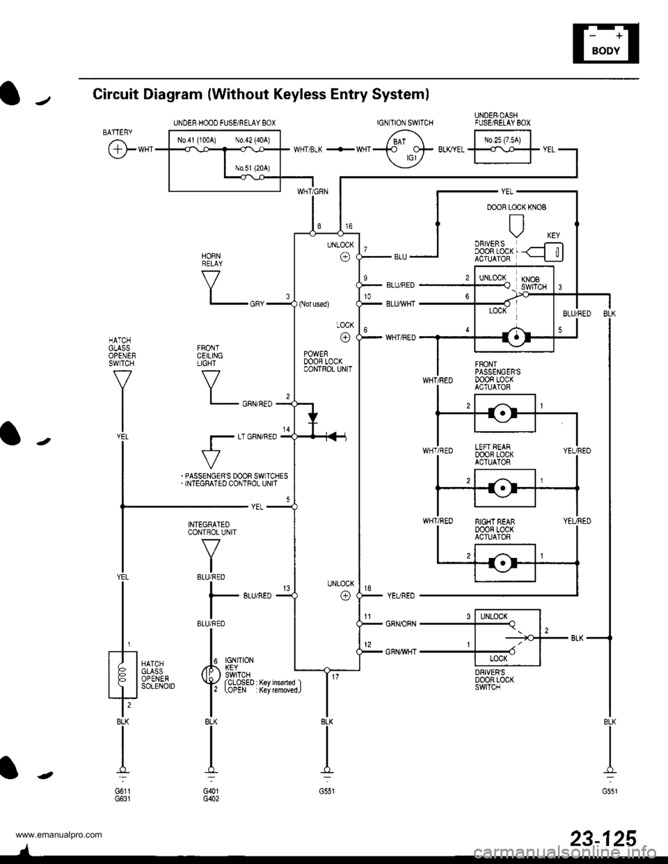
UNDER-DASHFUSE/RELAYBOX
Circuit Diagram {Without Keyless Entry System)
IGNTION SWITCHBATTEBY
@**'
FRONTCEILINGTIGHT
V
l_
r-
HATCHGLASSOPENERSWTCH
f7
I
l-J';
tr| oBtvERsI DOOn LOCKACTUATOR
s l-lLocx^l-Tq. l,, | -=tGJ--
+ II Locx IDRIVER'SD00R LOC(SWITCN
KNOB
6 tr.*;lwrr 3-K +wqr-t_t- BLKYEL
ffr
vEL
YEURED
GRNORN
GRNWHT
HORNRELAY
V
BLK
II
I:
G551
23-125
INTEGRATEDCONTROL UNIT
V
IBLU/RED
I
l- 8Lr
IBLU/RED
II
Iupl ,#. L?Vno'::iii^ ( li: ) swrTcHYAil''"',4,.'{yrcLosED
l' tottt
IBLK
II
I':
G()1G402
YEL
t/ |
tFl
?BLK
I
G6l1
UNDER.HOOD FUSEi RELAY 8OX
(Nol used)
LOCK
o
POWERDOOR LOCKCONTROL UNIT
EIGHT REAR00oR LocKACTUATOR
'tl
www.emanualpro.com