Drive HONDA CR-V 1999 RD1-RD3 / 1.G Workshop Manual
[x] Cancel search | Manufacturer: HONDA, Model Year: 1999, Model line: CR-V, Model: HONDA CR-V 1999 RD1-RD3 / 1.GPages: 1395, PDF Size: 35.62 MB
Page 969 of 1395
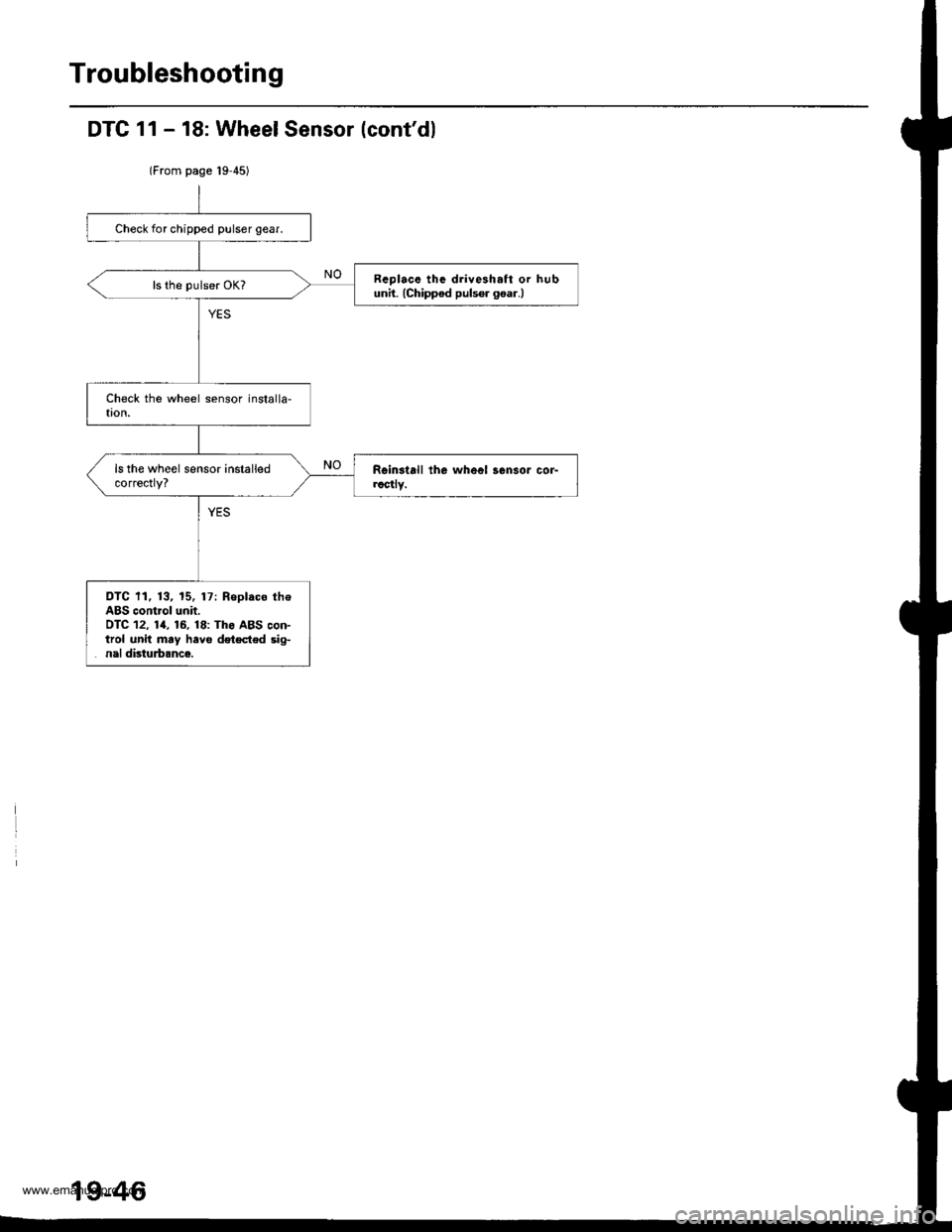
Troubleshooting
DTC 11 - 18: Wheel Sensor (cont'd)
Check for chipped pulser gear.
Rcplacs thc drive3haft or hubunh. (Chipped pulsor goar.l
DTC 11, 13, 15. 17: Replaco theABS control unit.OfC 12, 11, 16, 18: Th6 ABS con-trol unit may have dstected dg-n.l disturbsnc€.
19-46
www.emanualpro.com
Page 978 of 1395
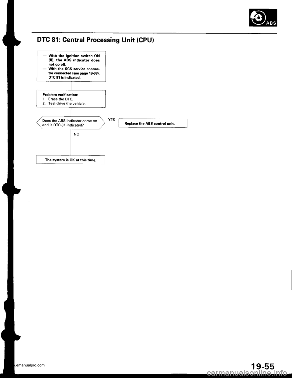
DTC 81: Central Processing Unit (CPUI
- with the ignition 3witch ON{ll}. the ABS indicator doesnot go off.- Whh the SCS sewice connec-tor connectod {see page 1938),DTC 81 b indicatod.
Problem vorific.tion:L Erase rne u t L.2. Test-drive the vehicle.
Does the ABS indicator come onand is DTC 81 indicated?R€place th. ABS control unit.
The system is OK at this time.
19-55
www.emanualpro.com
Page 979 of 1395
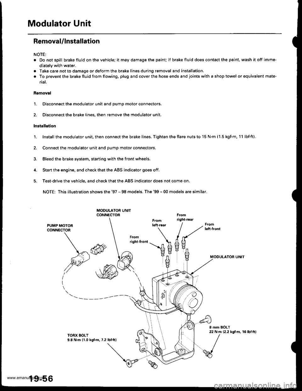
Modulator Unit
Removal/lnstallation
NOTE:
. Do not spill brake fluid on the vehicle; it may damage the painu if brake fluid does contact the paint, wash it off imme-
diately with water.
a Take care not to damage or deform the brake lines during removal and installation.
. To prevent the brakefluidfrom flowing, plug and coverthe hose ends and joints with a shop towel or equivalent mate-
rial,
Romoval
1. Disconnect the modulator unit and Dump motor connectors.
2. Disconnect the brake lines, then remove the modulator unit.
lnstallation
1. Install the modu lator u nit. then con nect the brake lines. Tighten the flare nuts to 15 N.m ( 1.5 kgf.m, 1 1 lbf.ft).
2. Connect the modulator unit and oumo motor connectors.
3. Bleed the brake system, staning with the front wheels.
4. Start the engine, and check that the ABS indicator goes off.
5. Test-drive the vehicle, and check that the ABS indicator does not come on,
NOTE: This illustration shows the '97 - 98 models. The'99 - 00 models are similar.
PUMP MOTORCONNECTOR
MODULATON UNIT\*\
,@
I
TORX EOLT9.8 N,m (1.0 kgf.m.7.2lbf ftl
19-56
www.emanualpro.com
Page 982 of 1395
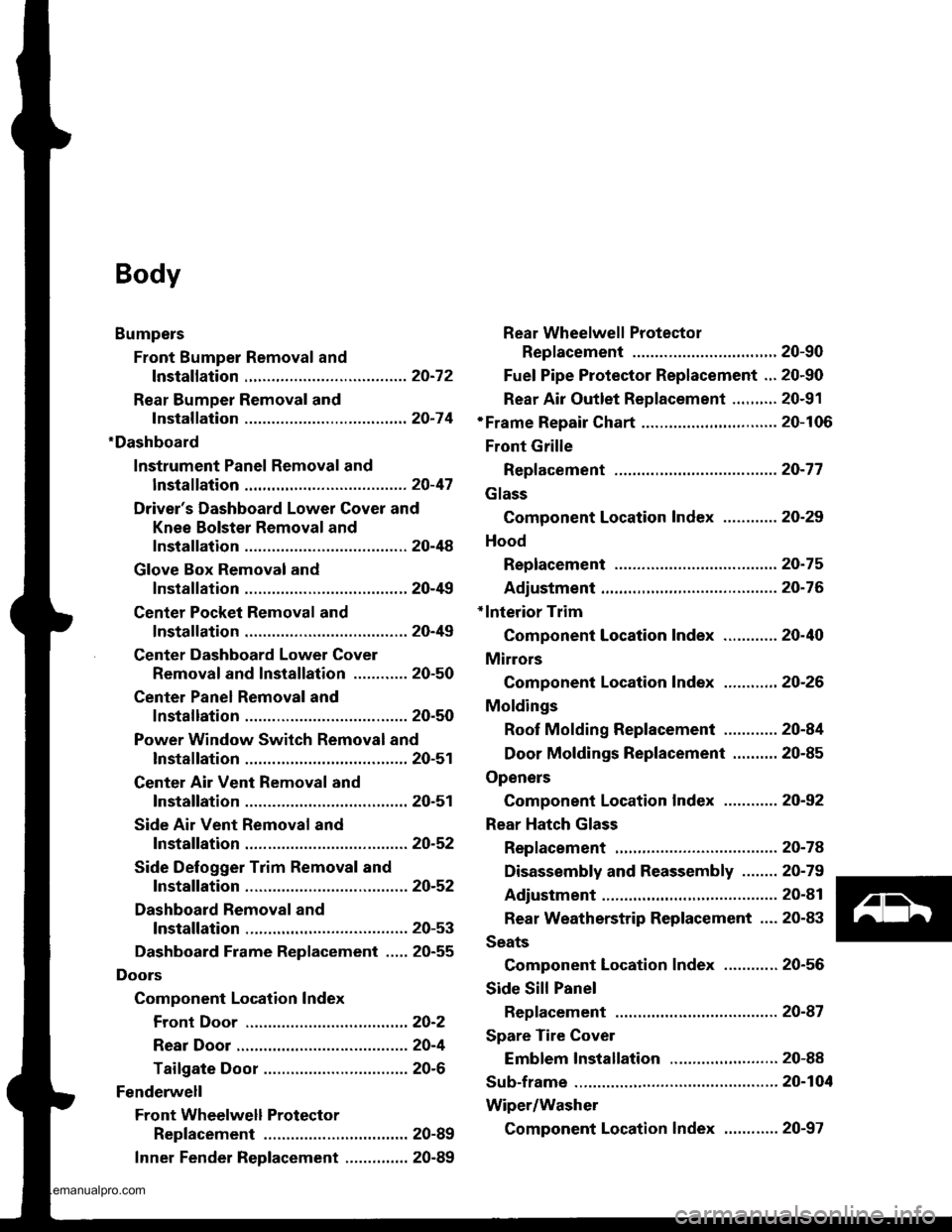
Body
Bumpers
Front Bumper Removal and
fnstaflation .........20-72
Rear Bumper Removal and
fnstaflation .........20-74
'Dashboard
lnstrument Panel Removal and
lnstallation .........20-47
Driver's Dashboard Lower Cover and
Knee Bolster Removal and
Installation .........20-48
Glove Box Removal and
lnstallation .........20-49
Center Pocket Removal and
lnstallation .........20-49
Center Dashboard Lower Cover
Removal and lnstallation ............ 20-50
Center Panel Removal and
lnstallation .........20-50
Power Window Switch Removal and
lnstallation .........20-51
Center Air Vent Removal and
lnstallation .........20-51
Side Air Vent Removal and
fnstallation .........20-52
Side Defogger Trim Removal and
fnstallation .........20-52
Dashboard Removal and
lnstallation .........20-53
Dashboard Frame Replacement ..... 20-55
Doors
Component Location Index
Front Door ,,...,,,,20-2
Rear Door ...........20-4
Tailgate Door ................................ 20-6
Fenderwell
Front Wheelwell Protector
Replacement .....20-89
Inner Fender Replacement .,.....,.,.... 20-89
Rear Wheelwell Protectol
Replacement .....20-90
Fuel Pipe Protector Replacement ... 20-90
Rear Air Outlet Replacement .......... 20-91
*Frame Repair Chart .............................. 20-106
Front Grille
Repf acement .........20-77
Glass
Component Location Index ............ 20-29
Hood
Replacement ......,,,20-75
Adjustment ............20-76
*lnterior Trim
Component Location Index ............ 20-40
Mirrors
Component Location Index .........,,, 20-26
Moldings
Roof Molding Replacement ............ 20-84
Door Moldings Replacement .......... 20-85
Openers
Component Location Index ............ 20-92
Rear Hatch Glass
Replacement .........20-74
Disassembly and Reassembly ........ 20-79
Adiustment ............20-81
Rear Weatherstrip Replacement .... 20-83
Seats
Component Location Index ............ 20-56
Side Sill Panel
Repfacement .........20-87
Spare Tire Cover
Emblem Installation ........................ 20-88
Sub-frame ..................20-104
Wiper/Washer
Component Location lndex ,,,,,....... 20-97
www.emanualpro.com
Page 1016 of 1395
22.
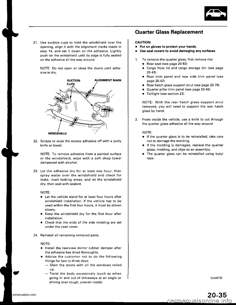
21. Use suction cups to hold the windshield over the
opening, align it with the alignment marks made in
step 14, and set it down on the adhesive. Ljghtly
push on the windshield until its edge is fully seated
on the adhesive all the way around.
NOTEr Do not open or close the doors until adhe-
sive is dry.
SUCTTON ALIGNMENT MARK
Scrape or wipe the excess adhesive off with a putty
knife or towel.
NOTE: To remove adhesive from a painted surface
or the windshield, wipe with a soft shop towel
dampened with alcohol.
Let the adhesive dry for at least one hour, then
spray water over the windshield and check for
leaks. mark leaking areas, and let the windshield
dry, then seal with sealant.
NOTE:
. Let the vehicle stand for at least four hours after
windshield installation. lf the vehicle has to be
used within the first four hours, it must be driven
. Keep the windshield dry for the first hour after
installation.
. Check that the ends of the side molding are set
under the cowl cover.
Reinstall all remaining removed parts.
NOTE:
. Install the rearview mirror rubber damper after
the adhesive has dried thoroughl,.
. Advise the customer not to do the following
things for two to three days:- Slam the doors with all the windows rolled
up.- Twist the body excess,vely {such as when
going in and out of driveways at an angle or
driving over rough. uneven roads).
24.
Ouarter Glass Replacement
CAUTION:
. Put on gloves to prot€ct your hands.
. Use seat covers to avoid damaging any surfaces.
1. To remove the quarter glass, first remove the:
. Rear seat (see page 20-63)
. Cargo floor lid and cargo storage bin (see page
20 431
. Rear trim panel and rear side trim panel (see
page 20-421
. Rear hatch glass support strut (see page 20-78)
. Ouarter pillar trim panel (see page20-421
. Taillight (see section 23)
NOTE: With the rear hatch glass support strut
removed, you will need to support the rear hatch
glass by hand.
2. From inside the vehicle, use a knife to cut through
the quarter glass adhesive all the way around.
NOTE:
. lf the quaner glass is to be reinstalled, take care
not to damage the molding.
. lf the molding is damaged. replace the quarter
glass, molding, and clips as an assembly.
. The quarter glass can be reinstalled using butyl
tape.
(cont'd)
20-35
www.emanualpro.com
Page 1020 of 1395
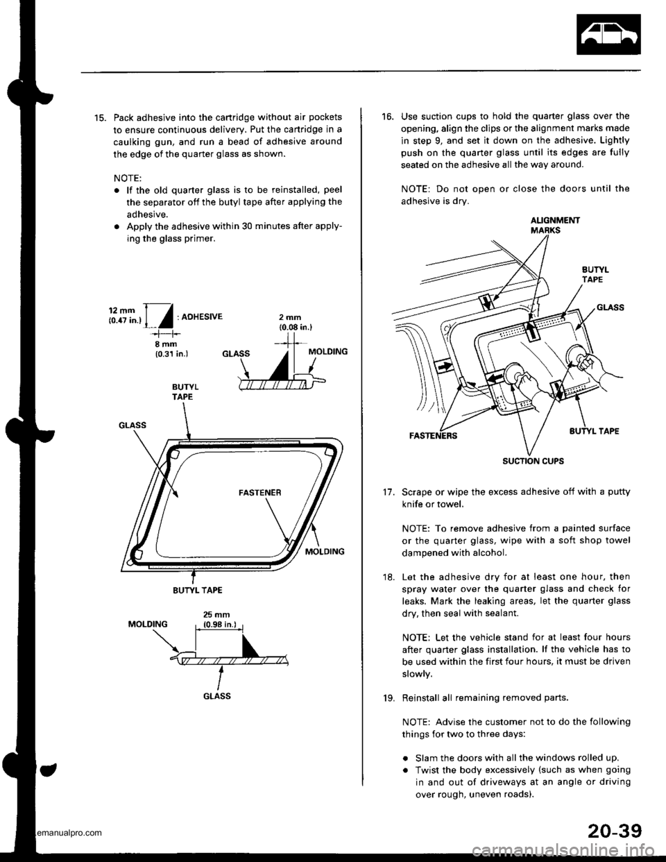
15. Pack adhesive into the cartridge without air pockets
to ensure continuous delivery, Put the canridge in a
caulking gun, and run a bead of adhesive around
the edge of the quarter glass as shown.
NOTE:
. lf the old quarter glass is to be reinstalled, peel
the separator off the butyl tape after applying the
adhesive.
. Apply the adhesive within 30 minutes after apply-
ing the glass primer.
i:.8T".,1,/:AoHEsrvE
I rnm(0.31 in.)
BUTYLTAPE
GLASS19.
20-39
16. Use suction cups to hold the quarter glass over the
opening, align the clips or the alignment marks made
in step 9, and set it down on the adhesive. Lightly
push on the quaner glass until its edges are fully
seated on the adhesive all the way around.
NOTE: Do not open or close the doors until the
adhesive is drv.
Scrape or wipe the excess adhesive off with a putty
knife or towel,
NOTE: To remove adhesive from a painted surface
or the quarter glass, wipe with a soft shop towel
dampened with alcohol.
Let the adhesive dry for at least one hour. then
spray water over the quarter glass and check for
leaks. Mark the leaking areas, let the quarter glass
dry, then seal with sealant.
NOTE: Let the vehicle stand for at least four hours
after quarter glass installation. lf the vehicle has to
be used within the first four hours, it must be driven
slowly.
Reinstall all remaining removed parts.
NOTE: Advise the customer not to do the following
things for two to three days:
. Slam the doors with all the windows rolled up.
. Twist the body excessively (such as when going
in and out of driveways at an angle or driving
over rough, uneven roads).
11.
18.
AUGNMENT
SUCTION CUPS
www.emanualpro.com
Page 1022 of 1395
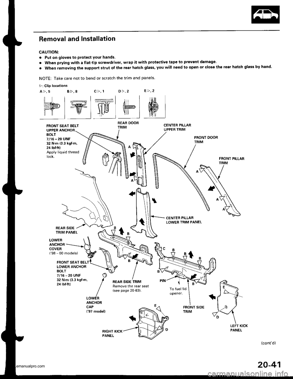
Removal and Installation
CAUTION:
. Put on gloves to protect your hands,
. When prying with a tlat-tip screwdrivel, wrap it with protective tape to prevent damage.
. When removing the support strut of the rear hatch glass, you will need to open or close the rear hatch glass by hand.
NOTE: Take care not to bend or scratch the trim and panels.
>: Clio locations
a>,5c>, 1o>.2e>,2B >,8
UPPERBOLT7/16 - 20 UNF32 N.m {3.3 kgf.m,24 rbt.ft)Apply liquid thread
CENTER PILLARLOWER TRIM PANEL
LOWERANCHOBCOVER('98 00 models)
{cont'd)
I l_lss-l , | 'rrl
elElw"lel sl
FRONT SEAT BELT
FRONT SEAT BELLOWER ANCHORBOLT7/15 - 20 UNF32Nm(3.3kgf.m,24 tbt.ftl
ANCHORCAP('97 model)
REAR DOORTRIM
REAR SIDE TRIMtlemove the rear seat(see page 20 63).
REAR SIDE
20-41
www.emanualpro.com
Page 1025 of 1395
lnterior Trim
Headliner Removal and Installation
CAUTION: When prying with a tlat-tip screwdriver,
wrap it with protective tape to prevent damage.
NOTE:
. Take care not to bend and scratch the headliner.o Be careful not to damage the dashboard and other
interior trim.
1. Remove:
. Front and rear door side trim (see page 20-41). Front pillartrim (see page 20-41)
. Center pillar lower trim panel (see page 20-41). Center pillar upper trim (see page 20 41). Rear seat (one side, see page 20-63). Cargo area floor and cargo storage bin
{see page 20-43)
. Rear trim panel (see page 20-421
. Rear side trim panel (oneside, see page 20-42l,
. Rear hatch glass support strut (one side, seepage 20-78)
. Ouaner pillar trim panel {one side, see page 20-
42)
. Ceiling light, interior light and trunk light(see section 23)
. Rearview mirror (see page 20-28)
2. Remove the sunvisor and holder from each side.
>: Scaew location3, 4
I
A\"r- |Yr* || -
suNvtsoR
20-44
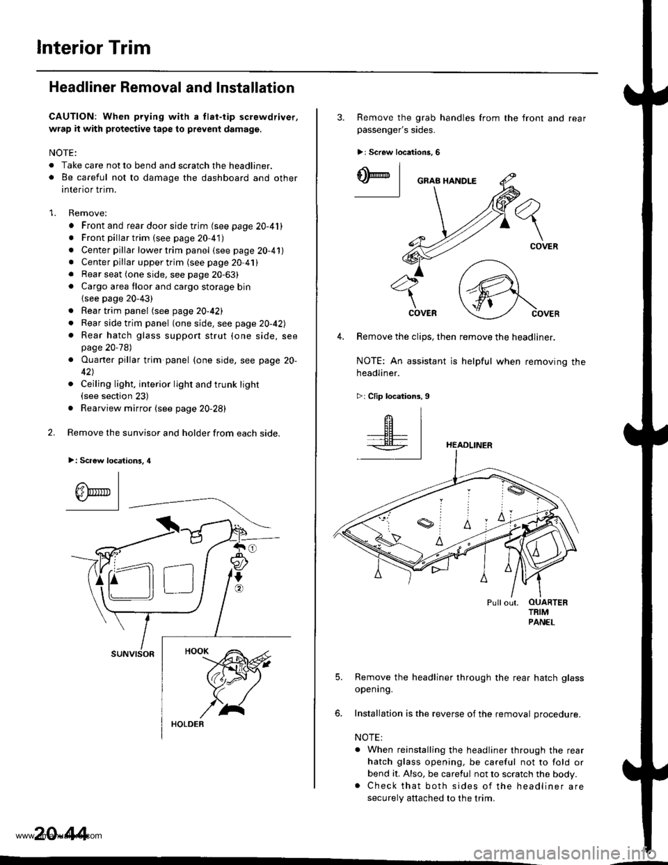
3. Remove the grab handles from
passenger's sides.
>r Screw locations, 6
the front and rear
ry_l
COVER
4. Remove the clips, then remove the headliner.
NOTE: An assistant is helpful when removing the
headliner.
>: Clip locations,9
HEADLINER
Pullout. OUARTERTRIMPANEL
5. Remove the headliner through the rear hatch glass
openrng.
6. Installation is the reverse of the removal procedure.
NOTE:
. When reinstalling the headliner through the rear
hatch glass opening, be careful not to fold or
bend it, Also, be careful not to scratch the body.. Check that both sides of the headliner are
securely attached to the trim.
www.emanualpro.com
Page 1028 of 1395
Dashboard
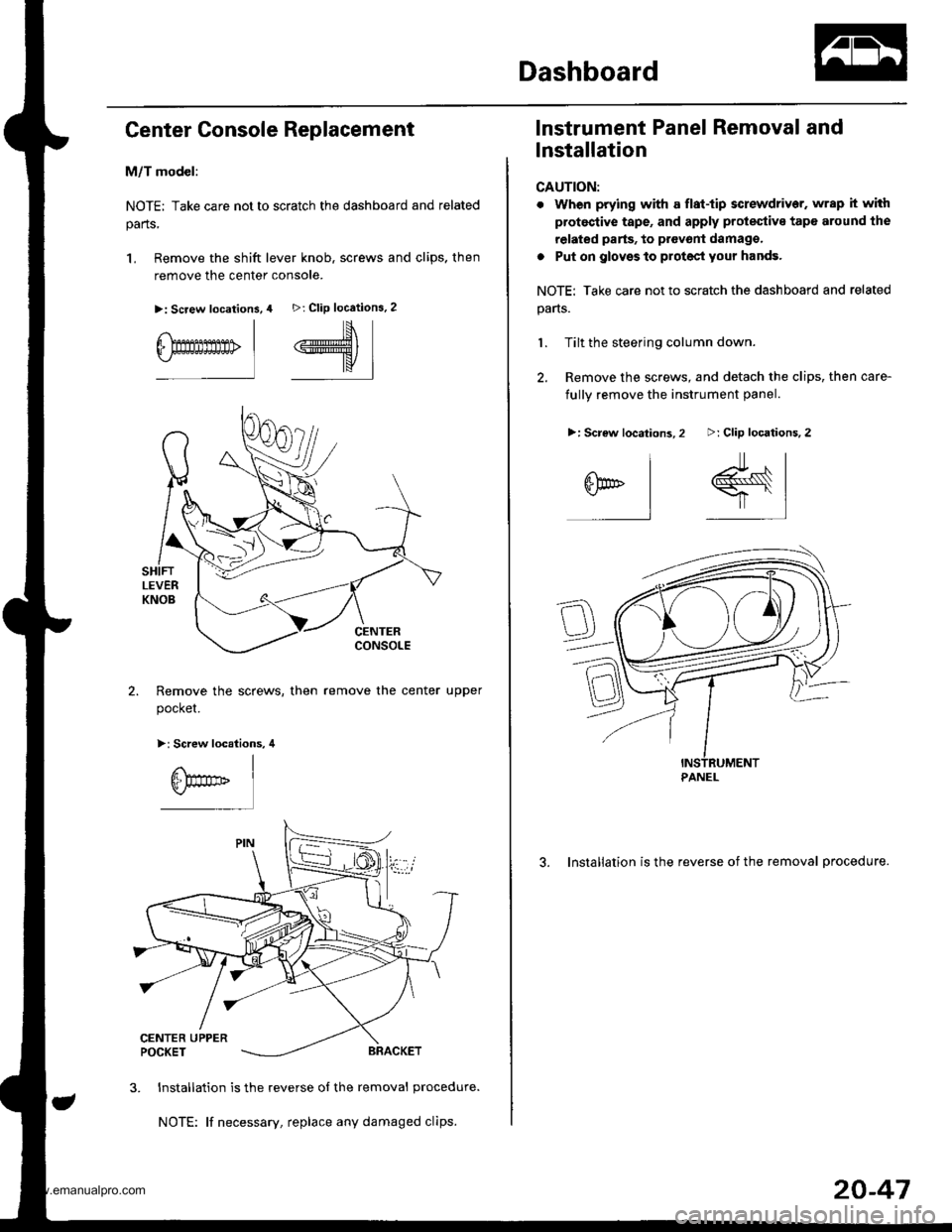
Genter Console Replacement
M/T model:
NOTE; Take care not to scratch the dashboard and related
parts,
1, Remove the shift lever knob. screws and clips. then
remove the center console.
>: Screw location3,
I
6-Emmmn> |
4 >: Clip locations.2
#\*K/
I
Remove the screws, then
pocket.
remove the center upper
>: Screw locations, 4
3. Installation is the reverse of the removal procedure.
NOTE: lf necessary, replace any damaged clips.
lnstrument Panel Removal and
Installation
CAUTION:
. When prying with a flat-tip screwdriver. wrap it with
protestive tape, and apply prolestive tape around the
related parts, to provont damago,
a Put on glovss to protect your hands.
NOTE: Take care not to scratch the dashboard and related
pans.
1. Tilt the steering column down.
2. Remove the screws, and detach the clips, then care-
fullv remove the instrument oanel.
3. Installation is the reverse of the removal procedure.
>: Clip locations,2
r#sr |
=-l,]
>: Screw locations,2
^l
arl
l
PANEL
20-47
www.emanualpro.com
Page 1029 of 1395
Dashboard
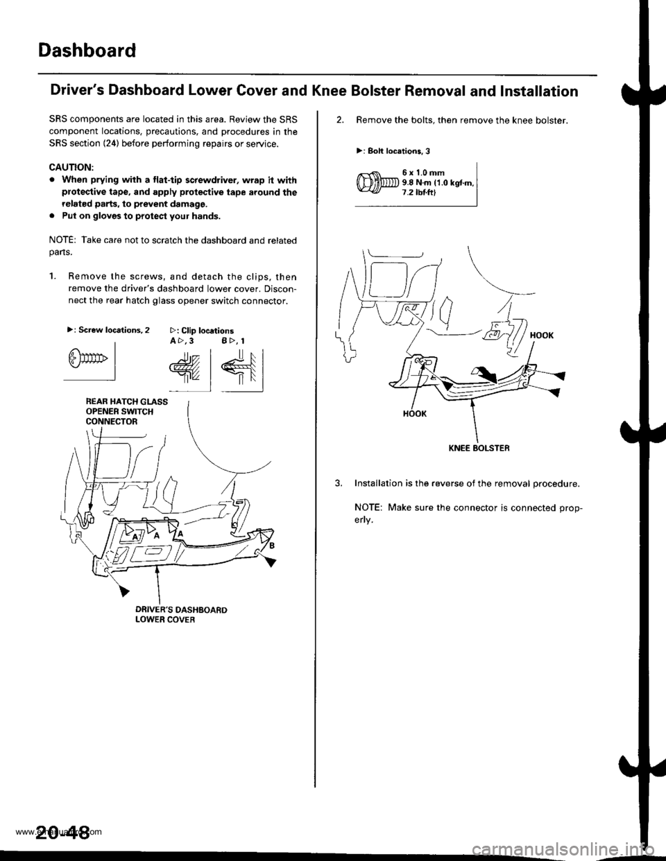
SRS components are located in this area. Review the SRS
component locations, precautions, and procedures in the
SRS section (24) before performing repairs or service.
GAUTION:
. When prying with a tlat-tip screwdriver, wrap h withproteqtive tape, and apply protective tape around the
relat€d parts, to prevent damage,
. Put on glovgs to protect your hands.
NOTE: Take care not to scratch the dashboard and relatedpans.
1. Remove the screws, and detach the clips, then
remove the driver's dashboard lower cover. Discon-
nect the rear hatch glass opener switch connector.
>: Clip locationsA >,3 B>, 1
rr.- | lr, l
@, | €{lr'" 1 |'l
>: Screw locations,2
IGlTtrrrb I.-l
REAR HATCH GLASSOPENER SWITCHCONNECTOR
20-48
'-
Driver's Dashboard Lower Cover and Knee Bolster Removal and Installation
2. Remove the bolts. then remove the knee bolster.
>: Boh locations,3
6x1.0mm9.8 N.m ('1.0 kgtm.7.2 tbtftl
3. Installation is the reverse of the removal procedure.
NOTE: Make sure the connector is connected prop-
erly.
KNEE BOLSTEF
www.emanualpro.com