Ect switch HONDA CR-V 1999 RD1-RD3 / 1.G Workshop Manual
[x] Cancel search | Manufacturer: HONDA, Model Year: 1999, Model line: CR-V, Model: HONDA CR-V 1999 RD1-RD3 / 1.GPages: 1395, PDF Size: 35.62 MB
Page 1126 of 1395
Troubleshooting
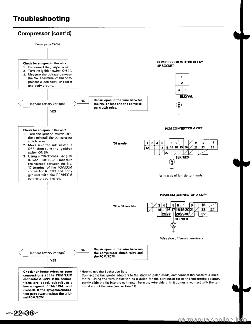
Compressor (cont'dl
COMPRESSOR CLUTCH RELAY4P SOCKET
1
2
43
BLK/YEL
PCM CONNECTOB A I32P)
'97 model:
Wire side of female terminals
PCM/ECM CONNECTOR A {32P}
38 - 00 models:
Wire side of {em6le terminals
* How to use the BackDrobe SetsConnect the backprobe adapters to the stacking patch cords, and connect the cords to a multi-meter. Using the wire insulation as a guide for the contoured tip ot the backprobe adapter,gently slide the tip into the connector trom the wire side until it comes in contact with the teFminalend o{the wire {see section l1).
Frcm page 22-34
Ch6ck for an open in the wire:1. Disconnect the jumper wire.2. Turn the ignition switch ON (ll).
3, Measure the voltage betweenthe No. 4 terminal ot the com'pressor clutch relay 4P socketand body ground.
Repair op.n in the wire betweenthe No. l7 fu3e and the compres-sor clutch ielay.
Check for an opon in the wire:1. Turn the ignition switch OFF,then reinstall the compressorclutch relay.2. Make sure the A"/C switch isOFF, then turn the ignitionswitch ON (ll).
3. Using a *Backprobe Set (T/N
07SAZ - 001000A), measurethe voltage between the No.17 terminal ol the PCM/ECMconnector A (32P) and bodyground with the PC M/ECMconnectors connected,
Repair open in lhe wire betwoonthe compressor clutch r6lay andthe PCM/ECM.
Check tor loose wires or Doorconnections at the PCM,/ECMconnecto. A {32P1. lf the connec-tions are good, sub3titute aknown-good PCM/ECM, androcheck. lf the symptom/indica-tion goas away, replac€ the origi-nal PCM/ECM.
126I1011
12151617'181S222321
BLK/RED
22-36
www.emanualpro.com
Page 1127 of 1395
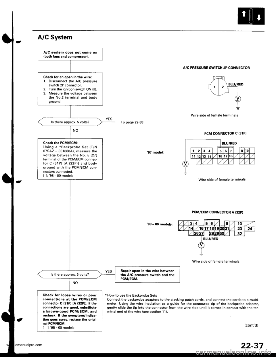
A/C aystem does not come on{both fans and comDrossor).
Ch6ck lor .n open in the wire:1. Disconnect the A,/C pressureswitch 2P connector.2. Turn the ignition switch ON (ll).
3. Measure the voltage betweenthe No.2 terminal and bodyground.
ls there approx. 5 volts?
check tho PcM/EcM:Using a *Backprobe Set (T/N
07SAZ 0010004). measure thevoltage between the No.5 t27lterminal of the PCM/ECM connec,tor C (31P) [A 132P)l and bodyground with the PCM/ECM con-nectors connected,I l: '98 - 00 models
Rop.ir open in th6 wire botweonthe A/C Dr*sure switch and thePCM/ECM.
ls there approx.5 volts?
Check tor loo3e wires or Doorconnections at the PCM/ECMconnoctor C l3lPl lA (32Pll. It theconnections arg good, 3ubdtitut€a known-good PCM/ECM, andrecheck. ll the 3ymptom/indica-tion go.. eway, r€placo thG origi-nal PCM/ECM,[ ]: '98 -00 models
A/C System
A/C PRESSURE SWITCH 2P CONNECTOR
fo page 22-38
PCM CONNECTOR C (31PI
'97 modol:
Wire side of female terminals
PCM/ECM CONNECTOR A I32P'
38 - 00 modeb:
Wire side of female terminals
* How to use the Backprobe SetsConnect the backprobe adapters to the stacking patch cords, and connect the cords to a multi-meter. Using the wire insulation as a guide for the contoured tip ol the backprobe adapter,gently slide the tip into the connector from the wire side until it comes in contact with the ter.minalond olthe wire (see section 11).
(cont'd)
22-37
www.emanualpro.com
Page 1128 of 1395
Troubleshooting
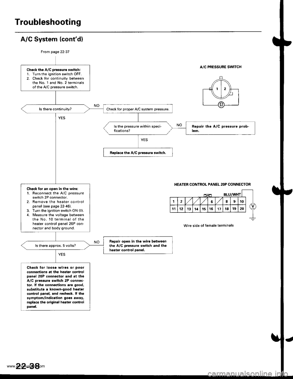
A/G System {cont'd)
From page 22-37
A/C PRESSURE SWITCHCheck th€ A/C pressure switch:1. Turn the ignition switch OFF.2. Check lor continuity bgtweenthe No. 1 and No.2 terminalsofthe A,/C pressure switch.
Check for proper Ay'C system pressure.
Roplece tha A/C pr€ssure switch.
Chock lor an opgn in thg wire:1. Feconnect the A/C pressure
switch 2P connector,2. Remove the heater controlpanel (see page 22-46).3. Turn the ignition switch ON llli.4. Measure the voltage betweenthe No. 10 terminal of theheater control panel 20P con-nector and body ground.
Repair open in the wir. botwcenthe A/C pres3ur€ switch and theheater control oanel.ls there approx. 5 volts?
Check lor loos6 wiras or pool
connections at the heater controlDanel 20P connoctor and at theA/C pr.ssule switch 2P connsc-tor. lf the connections ere good,
substitute a known-good heatarco trol pangl, end recheck. lf thesymptom/indication goes away,replace the original heater conlrolpanel.
HEATER CONTROL PANEL 2OP CONNECTOR
Wire side ol female terminals
22-38'
www.emanualpro.com
Page 1129 of 1395
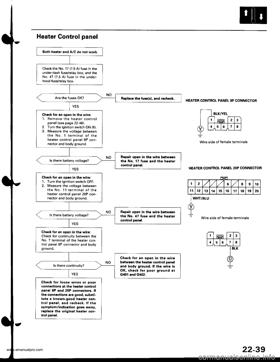
Both heater and A/C do not work.
Check the No. 17 (7.5 A)fuse in theunder-dash fuse/relay box, and theNo. 47 (7.5 A) fuse in the under-hood luse/relay box.
nophcc ih. fur.l.l, .nd r.check.
Check tor rn open in the wiro:1. Remove the heater controlpanellsee page 22 46).2. Turn the ignition switch ON (ll).3. Measure the voltage betweenthe No. 1 terminal of theheater control panel 8P con-nector and body ground.
R.pair opan in lha wlra batw.cnthe No. 1? fuaa and tha h.ltcrcontrol panal.ls thero battery voltage?
Chgck for an opan in th€ wirg:1. Turn the ignition switch OFF.2. Measure the voltage betweenthe No. l l terminal of thoheater control panel 20P con-noctor and body ground.
Repsil opon in tha wi.a batwcanth. No. 47 tur. and tho hoitorcontlol panol.
ls there battery voltags?
Check for an opon in the wire:Ch6ck lor continuity betwoen theNo. 7 terminal of the heater con-trol panel 8P connector and bodyground.
Check for an opon in tho wirab6{woon tho hoatar control p.noland body ground. It the wir. i3OK, chsck for poor ground rtGlOl lnd Glo2.
Check for loose wire3 or oooaconnection3 at the haater controlprnol 8P and 20P connoctors. Itthc conncction3 are good, substi-tuta a known-good h€ater con-trol prnol, and rechecft. lf thesymptom/indic.lion go.3 ewry,repl.cg the original ha.ter con-tlol oancl.
HEATER CONTROL PANEL 8P CONNECTOR
Wire side ot female terminals
HEATER CONTROL PANEL 2OP CONNECTOR
I2A,/1,/58910
1t12131a151517181920
WHT/BLU
Wire side of female terminals
23
{578
BLK
0
www.emanualpro.com
Page 1130 of 1395
Troubleshooting
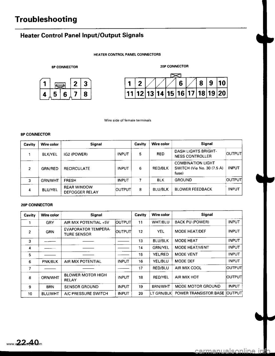
Heater Control Panel Input/Output Signals
HEATER CONTROL PANEL CONNECTORS
8P CONNECTOR
Wire side of female terminals
2OP CONNECTOR
8P CONNECTOR
Cavitylrvire cololSignalCavityWire cololSignal
'lBLK/TE LIG2 (POWER)INPUTREDDASH LIGHTS ERIGHT-
NESS CONTROLLERCUTPUT
2GRN/REDRECIRCULATEINPUTRE D/BLK
COMBINATION LIGHT
SWITCH (Via No. 30 (7.5 A)
fuse)
INPUT
GRN/VVHTFRESHINPUT1BLKGROUNDOUTPUT
BLUI/ELREAR WINDOW
DEFOGGER RELAYCUTPUT8BLU/BLKBLOWER FEEDBACKINPUT
20P CONNECTOR
CavityWire colorSignalCavityWire colorSignal
1GRYAIR MIX POTENTIAL +5VOUTPUT'llWHT/BLUBACK PU (POWER)INPUT
2GRNEVAPORATOR TEMPERA.
TURE SENSOROUTPUT12YELMODE HEAT/DEFINPUT
13BLU/BLKMODE HEATINPUT
14GRN/YELMODE HEAT/VENTINPUT
ICYEUREDMODE VENTINPUT
6PNI(BLKAIR MIX POTENTIALINPUTtoYEUBLUMODE DEFINPUT
717RED/BLUAIR MIX COOLOUTPUI
8ORNrur'HTBLOWER MOTOR HIGH
RELAYINPUT18RE D/VE LAIR MIX HOTOUTPUI
BRNSENSOR GROUNDINPUT'19BRNA/VHTIVIODE MOTOR GROUNDINPUT
10BLU,ryVHTA"/C PRESSURE SWITCHINPUT20T GRN/BLKPOWER TRANSISTOR BASECUTPUT
22-40
www.emanualpro.com
Page 1134 of 1395
Evaporator Temperature
SensorPower Transistor
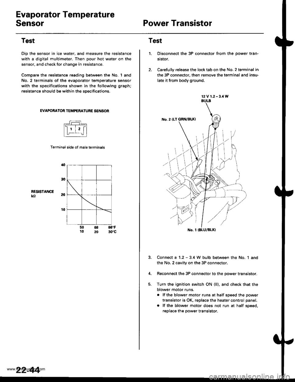
Test
Dip the sensor in ice water, and measure the resistance
with a digital multimeter. Then pour hot water on the
sensor, and check lor change in resistance.
Compare the resistance reading between the No. | 8nd
No. 2 terminals of the evaporator temperature sensor
with the specifications shown in the following graph;
resistance should be within the specifications.
EVAPOBATOR TEMPERATURE SENSOB
Terminal side ol male terminals
4
RESISTANCEko
t0
50 68 86.F10 20 30'c
22-44
12V 1.2-3.1W
No. 2 ILT GRN/BLK)
No. I IBLU/BLK)
Test
1.Disconnect the 3P connector from the oower tran-
st$or.
Carefully release the lock tab on the No. 2 terminal in
the 3P connector, then remove the terminal and insu-
late it from body ground.
Connect a 1.2 - 3.4 W bulb between the No, 1 and
the No,2 cavity on the 3P connectol
Reconnect the 3P connector to the power transistor.
Turn the ignition switch ON (ll). and check that the
blower motor runs.
a lf the blower motor runs at half soeed the oower
transistor is OK, replace the heater control panel.
. lf ths blower motor does not run at half soeed,
reDlaca the Dower transistor.
www.emanualpro.com
Page 1143 of 1395
Temperature Control
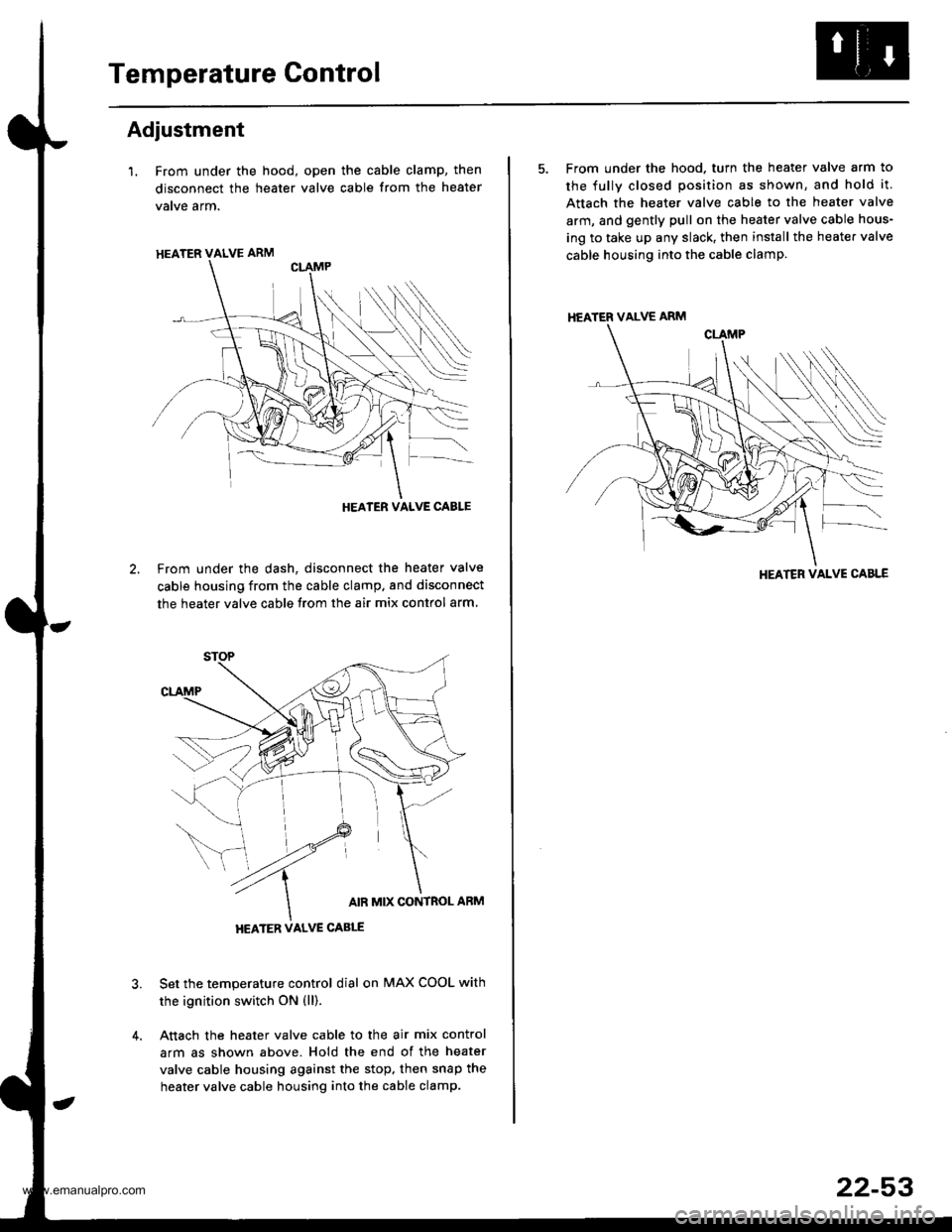
Adjustment
l. From under the hood, open the cable clamp, then
disconnect the heater valve cable from the heater
vatve arm.
From under the dash, disconnect the heater valve
cable housing from the cable clamp. and disconnect
the heater valve cable from the air mix contlol arm
Set the temperature control dial on MAX COOL with
the ignition switch ON (ll).
Attach the heater valve cable to the air mix control
arm as shown above. Hold the end of the heater
valve cable housing against the stop, then snap the
heater valve cable housing into the cable clamp.
HEATER VALVE ARM
HEATER VALVE CABLE
5. From under the hood. turn the heater valve arm to
the fullv closed position as shown, and hold it.
Attach the heater valve cable to the heater valve
arm, and gently pull on the heater valve cable hous-
ing to take up any slack, then install the heate. valve
cable housing into the cable clamp.
HEATER VALVE ARM
HEATER VALVE CABLE
22-53
www.emanualpro.com
Page 1146 of 1395
A/G System Service
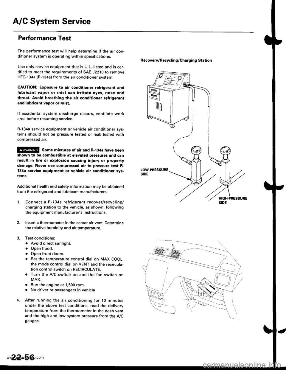
Performance Test
The performance test will helD determine if the air con-
ditioner system is operating within specifications.
Use only service equipment that is U.L.-listed and is cer-
tified to meet the requirements of SAE J2210 to remove
HFC-134a (R-134a) from the air conditioner svstem.
CAUTION: Exposure to air condiiioner r€trigerant and
lubricant vapor or mist can irritate €yes, nose and
throat. Avoid bre8thing the air conditioner retrige.ant
and lubricant vapor or mist,
lf accidental system discharge occurs. ventilate work
area before resuming service.
R-134a service equipment o. vehicle air conditioner sys-
tems should not be pressure tested or leak tested with
comDressed air.
@ some mixtur€s ol air and R-134a have becn
shown to be combuslible at olsvated pressures and can
result in lire or explosion causing iniury or property
damage. Never use compressed air to prgssure test R-
13i[a service equipment or vehicle air conditioner sys.
tems.
Additional health and safety information may be obtained
from the refrigerant and lubricant manufacturers.
Recovory/Recycling/charging station
LOW.PRESSURESIDE
1.Connect a R-134a refrigerant recover/recycling/
charging station to the vehicle, as shown. following
the equipment manufacturer's instructions,
Insen a thermometer in the center air vent. Determine
the relative humidity and air temperature.
Test conditions:
. Avoid direct sunlight.
o Open hood.
. open front doors.
. Set the temperature control dial on MAX COOL,
the mode control dial on VENT and the reci.cula-
tion control switch on RECIRCULATE.
. Turn the A,/C switch on and the fan switch on
MAX.
. Run the engine at 1,500 rpm.
. No driver or passengers in vehicle
After running the air conditioning for 10 minutes
under the above test conditions, read the deliverv
temperature from the thermometer in the dash vent
and the high and low system pressure from the Ay'Cgauges.
2.
22-56
www.emanualpro.com
Page 1161 of 1395

Body Electrical
Speciaf Toofs ,...,..,.............-.23-2
Troubleshooting
Tips and Precautions ......,.,..........,.................. 23-3
Five-step Troubleshooting ........,.,.,...,,.,......... 23-5
Wire Color Codes ...,....,.. 23-5
Relay and Control Unit Locations
Engine Compartment ..,.,......,......................... 23-6
Dashboard ,.,.,..............-.- 23-7
Door ....................... .........23-10
Index to Cilcuits and Sysiems
Accessory Socket .. ,....,.,..,.,. 23-95*Airbags ................ .,....,. Sestion 24
Air Conditioning ,.,.,.... Section 22
Alternator ................... Section 4
Anti-lock Brake System {ABSI ................... Section 19'A/T Gear Position Indicator ....................... Section 1,1
Automatic Transmission System ...........,.. Section 14
Battery ................... ..............23-50
Blower Controls .,...,.,, Section 22
Charging System ....... Seqtion il
Clock -'98 Model ................ 23-98
Connector ldentification and Wire HarnessRouting .................. ......... 23.11
Cruise Control ............ Ssction 4
Dash Lights Brightness Contlo||er ..................... 23-90
Fan Conlrols ...,......,.... Section 10
Fuel Pump ,..,.,...,....,.... Section 11
Fuses...................... .,,.,.,.,.,,.,23-40*Gauges
Circuit Diagram ......-....-..23-58
Fuel Gauge .....,.,..... Section 11
Speedometer ..,..........,... 23-56
Ground Distribution ,....,.,...23-46
Hatch Glsss ODenor .........................,.,.,.,.,..,.,.,.,,. 23-121
Heater Controls .-........ Soction 21*Horns.,...,..,.,.,....... ................23"104*fgnition Switch ,,.,.,..,.,.,,.,.,.,23-51
lgnition Key Light System -'97 Mod6l .............. 23.88
-+
BODY
www.emanualpro.com
Page 1171 of 1395

Gonnector ldentification and Wire Harness Routing
How to ldentity Connectors:
ldentification numbers have been assigned to all connectors, The number is preceded by the letter "C" for connectors.
"G" for ground terminals or "T" for non-ground terminals.
Location
HarnessEngine CompartmsntDashboardOthers lFloor, Door,
8oof, Tailgate)
Starter cableT1, T2 and @
Battery ground cableG1 and O
Engine ground cableT3
Transmission ground cableT4
G3
Engine wire harnessC101 through C137
T101 and T102
G101
Engine compartment ware harnessC201 through C218
G201 and G202
Under-hood ABS fuse/relay box
wire harness
t5ano9
Main wire harnessC301 through C309
C351 through C361
C401 through C447
G401 and G402
Dashboard wire harnessC501 through C524 (C525)
G501
Left side wire harnessC551 through C581
G551, G552 and G553
Right side wire harnessC601 through C605
lnterior wire harnessC701 through C703
Rear bumper wire harnessC641 through C643
Heater sub-harnessC731 through C740
Secondary heated oxygen sensor
sub-harness
C721 through C722
Combination switch sub-harnessC751 through C760
Driver's door wire harnessC661 through C667
Front passenger's door wire harnessC6Tl through C676
Left rear door wire harnessC681 through C684
Right rear door wire harnessC69'l through C694
Rear wire harnessC611 through C520
Tailgate wire harnessC631 through C634
G631
SRS main harnessC801 through C808
G801
High mount brake light sub-harnessC651 through C653
Fuel tank oressure sensor sub-harnessC645 through C647
www.emanualpro.com