Ect switch HONDA CR-V 1999 RD1-RD3 / 1.G Workshop Manual
[x] Cancel search | Manufacturer: HONDA, Model Year: 1999, Model line: CR-V, Model: HONDA CR-V 1999 RD1-RD3 / 1.GPages: 1395, PDF Size: 35.62 MB
Page 1383 of 1395
Troubleshooting
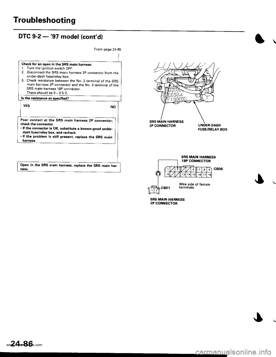
DTC 9-2 -'97 model lcont'dl
UNDER.OASHFUSE/RELAY BOX
SRS MAII{ HARI{ESS2P CONNECTOR
24-86
From page 24-85
Check for an open in the SRS main harness:1. Turn the ignition switch OFF.2. Disconnect the SRS main harness 2p connector from theunder-dash fuse/relay box.3. Check resistance between the No. 2 terminal of the SRSmain harness 2P connector and the No. 3 terminal of theSRS main harness 18P connector.There should be 0-0.5 0.
ls th6 resistance as soecified?
YESNO
Poor contact at the SRS main harness 2p connector;check tho connector,. lf the connector i3 OK, substituto a known-good und€r-dash fuse/relay box, and recheck.. lf the problem is still present, roplace the SRS mainnatness,
Open in the SRS main harn$s;.eplace the SRS main har-ness.
www.emanualpro.com
Page 1385 of 1395
Driver's Airbag
Replacement lcont'd)
CAUTION: 8. sure to instattthe SRS wiring so that it isnot plnched or inlerfsring with other parts.
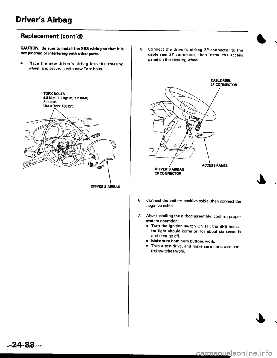
4. Place the new driver's airbag into the steeringwheel, and secure it with new Torx bolts.
TORX EOLTS9.8 N,m 11.0 kgl.m, 7.2 tbf,ftlFeplace.
24-88,
5. Connect the driver's airbsg 2p connector to thecable reel 2P connector, then install the accesspanel on the steering wheel.
Connect the battery positive cable. then connect thenegative cable.
After installing the airbag assembly, confirm proper
system operation:
. Turn the ignition switch ON llt); the SRS indica-tor light should come on for about six secondsand then go off.. Mske sure both horn buttons work.o Take a test-drive, and make sure the cruise con-trol switches work.
7.
2P CONNECTOR
www.emanualpro.com
Page 1387 of 1395
Front Passenger's Airbag
Replacement (cont'd)
GAUTION: Be sure to installthe SRS wiring so that it isnot pinched or interfering with olher parts.
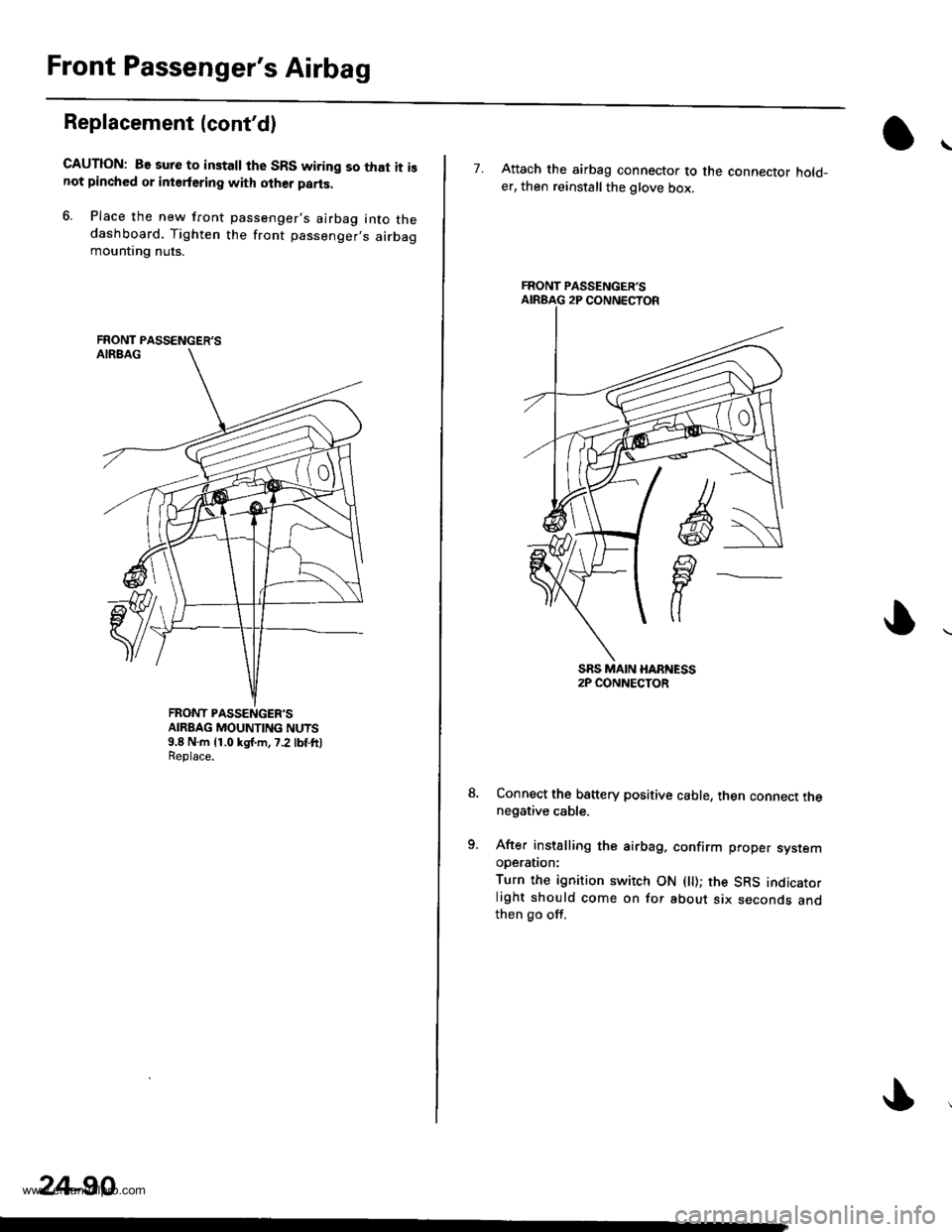
6. Place the new front passenger's airbag into thedashboard. Tighten the front passenger,s airbagmountrng nuts.
FRONT PASSENGER'SAIRBAG MOUNTING NUTS9.8 N.m {1.0 kgJ.m,7.2 lbf ft)Replace.
FRONT PASSENGER'S
24-90
7. Attach the airbag connector to the connector hold_er, then reinstall the glove box.
Connect the b8ttery positive cable, then connect thenegative cable.
After installing the airbag. confirm proper sysremooerauon:
Turn the ignition switch ON ( ); the SRS indicatorlight should come on for about six seconds andthen go off.
FRONT PASSENGER'S
www.emanualpro.com
Page 1389 of 1395
Gable Reel
Replacement (cont'dl
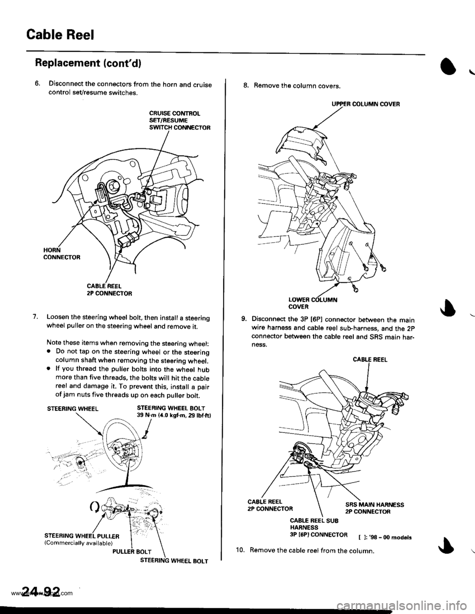
6, Disconnect the connectors from the horn and cruisecontrol sevresume switches.
cRursE coNtRoLSET/RESUMESWITCH CONNECTOR
1.Loosen the steering wheel bolt, then install a steeringwheel puller on the steering wheel and remove it.
Note these items when removing the stee.ing wheel:. Do not tap on the steering wheel or the steeringcolumn shaft when removing the steering wheel,. lf you thread the puller bolts into the wheel hubmore than five threads, the bolts will hit the cablereel and damage it. To prevent this. install a pair
of jam nuts five threads up on each puller bolt.
STEERING WHEEL BOLT39 N.m 14.0 kgf.m. 29 lbf.ftlSTEERING WHEEL
STEERING
2P CONNECTOR
24-92
8. Remove the column covers,
Disconnect the 3P [6P] connector between the mainwire harness and cable reel sub-harness, and the 2pconnector between the cable reel and SRS main har-ness.
CAALE REEL SU8HARNESS3P l6Pl CONNECTOR [ ]:,98_00modets
10. Remove the cable reelfrom the cotumn,
COVER
www.emanualpro.com
Page 1391 of 1395
Cable Reel
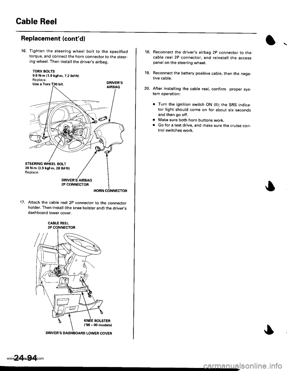
16.
Replacement (cont'dl
11.
Tighten the steering wheel bolt to the specifiedtorque, and connect the horn connector to the steering wheel. Then install the driver's airbag.
TORX BOLTS9.8 N.m (1.0 kgd.m,7.2 lbnftlReplace.DRIVER'S
Attach the cable reel 2P connector to the connectorholder. Then install (the knee bolster and)the driver,sdashboard lower cover.
BOLSTERl'98 - 00 modalsl
STEERING WHEEL BOLT38 N.m (3.9 kgl.m,28lbf.ftlReplace.
CABLE REEL
24-94
DRIVER'S DASHEOARD LOWER COVER
19.
20.
Reconnect the driver's airbag 2P connector to thecable reel 2P connector, and reinstall the accesspanel on the steering wheel.
Reconnect the battery positive cable, then the nega-tive cable.
After installing the cable reel, confirm proper sys-tem operation:
. Turn the ignition switch ON (ll); the SRS indica-tor light should come on for about six secondsand then go off.
a Make sure both horn buttons work.. Go for a test drive. and make sure the cruise con-trol switches work.
www.emanualpro.com
Page 1393 of 1395
SRS Unit
Replacement (cont'dl
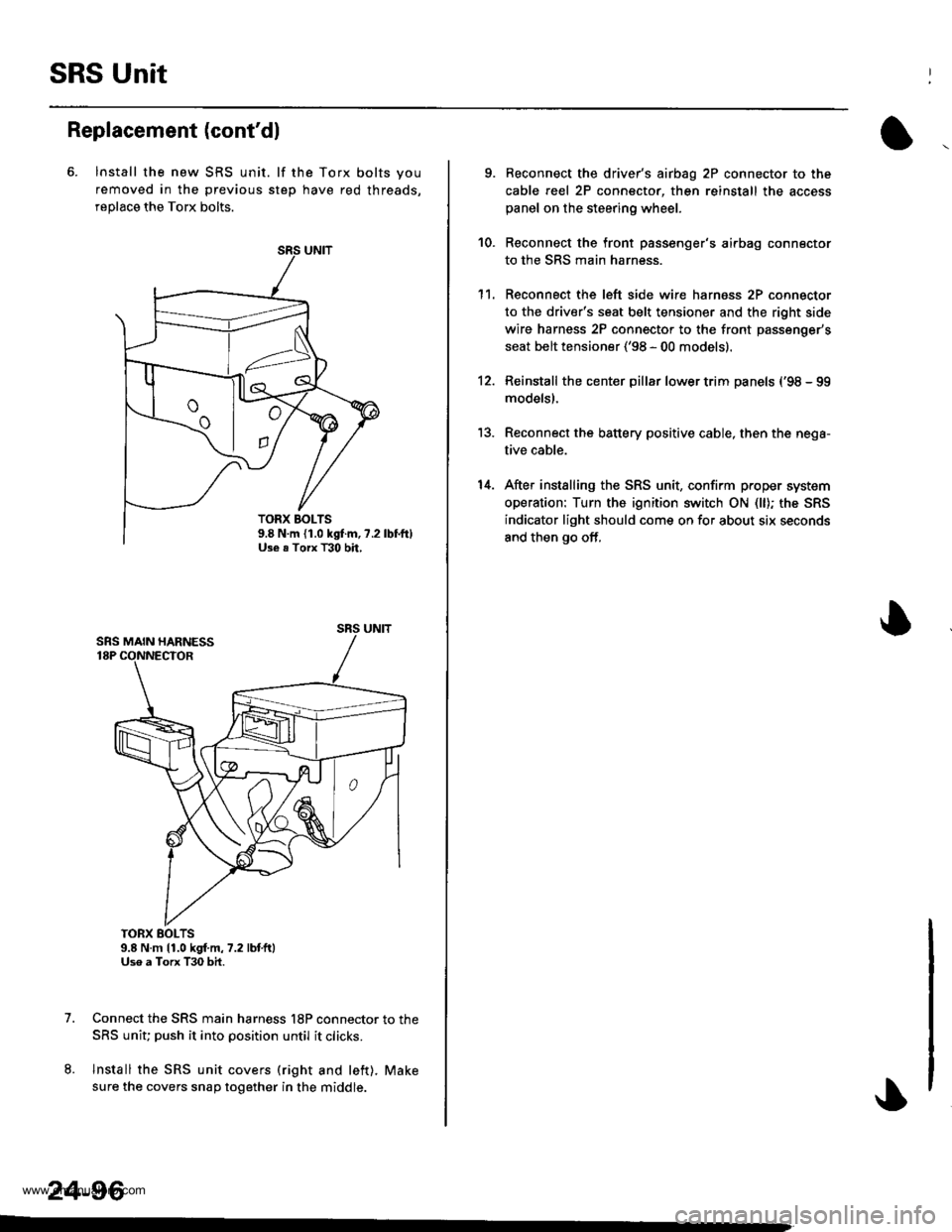
6. lnstall the new SRS unit. lf the Torx bolts you
removed in the previous step have red threads,
replace the Torx bolts.
TORX BOLTS9.8 N.m 11.0 kgf.m,7.2 lbtft)Uso a Torx T30 bit.
Connect the SRS main harness l8P connector to the
SRS uniu push it into position until it clicks.
Install the SRS unit covers (right and left). Make
sure the covers snap together in the middle.
7.
8.
TORX BOLTS9.8 N.m {1.0 kgf.m, ?.2Use . Torx T30 bh,
SRS UNIT
24-96
-
9. Reconnect the driver's aibag 2P connector to the
cable reel 2P connector, then reinstall the access
panel on the steering wheel.
Reconnect the front passenger's airbag connector
to the SRS main harness.
Reconnect the left side wire harness 2P connector
to the driver's seat belt tensioner and the right side
wire harness 2P connector to the front passenger's
seat belt tensioner ('98 - 00 models).
Reinstall the center pillar lower trim panels {'98 - 99
modelsl.
Reconnect the battery positive cable, then the nega-
tive cable.
After installing the SRS unit, confirm proper system
operation: Turn the ignition switch ON (ll); the SRS
indicator light should come on for about six seconds
and then go off,
10.
1't.
12.
13.
14.
www.emanualpro.com
Page 1395 of 1395
Airbag/Seat Belt Tensioner
1.
Disposal (cont'dl
Connect a 12 volt battery to the tool'
. It the green light on the tool comes on, the air-
bag igniter circuit is defective and cannot deploy
the airbag. Go to Damaged Airbag Special
Procedure.
.lftheredlightonthetool comes on, the airbag is
ready to be deployed.
Push the tool's deployment switch. The airbag
should deploy (deployment is both highly audible
and visible; a loud noise and rapid inflation of the
bag, followed by slow deflation).
. lf the airbags deploy and the green light on the
tool comes on, continue with this procedure.
. lf an airbag doesn't deploy, yet the green light
comes ON, its igniter is defective. Go to Dam-
aged Airbag Special Procedure.
. During deployment, the airbag can become hot
enough to burn you, Wait thirty minutes after
deployment before touching the airbag.
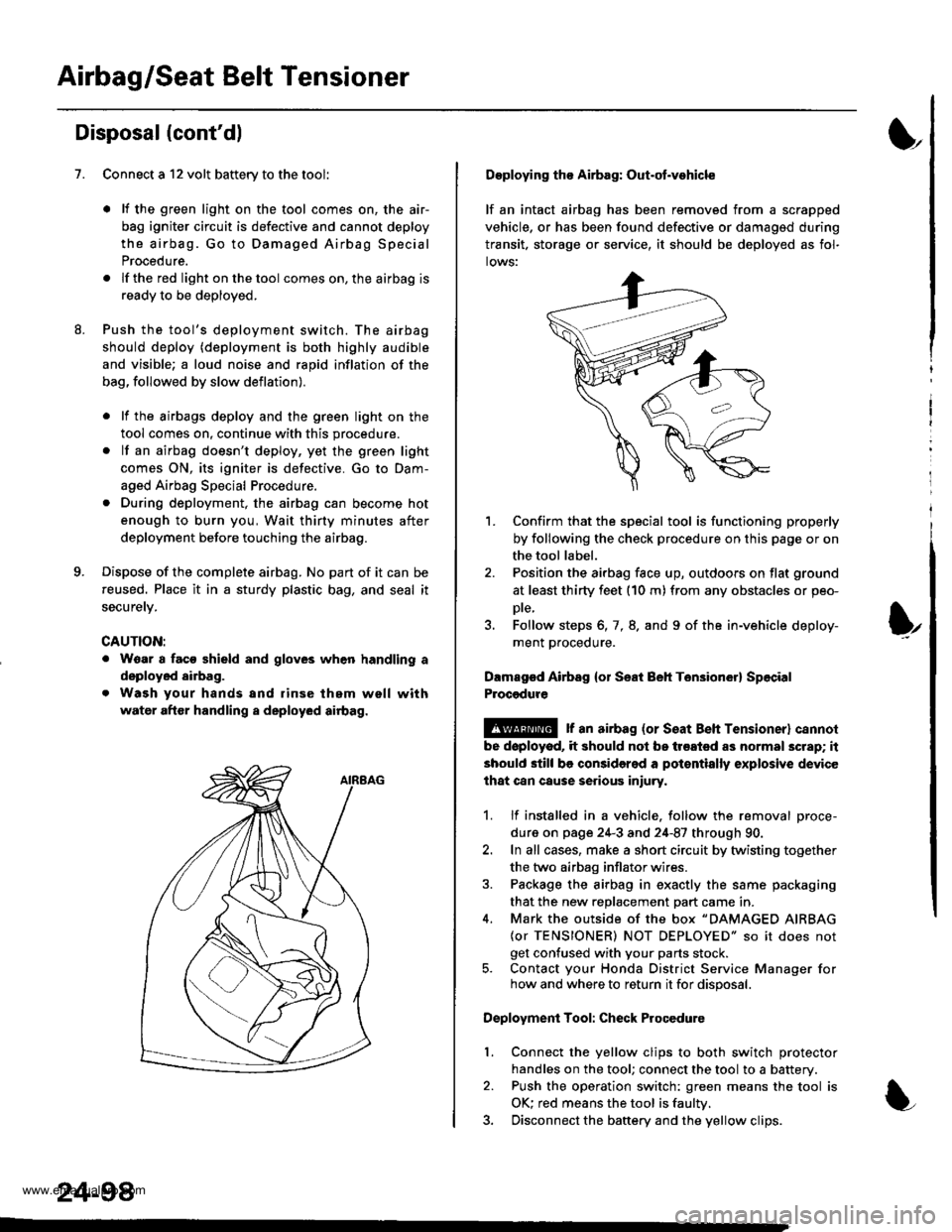
Dispose of the complete airbag. No part of it can be
reused. Place it in a sturdy plastic bag, and seal it
securety.
CAUTION:
. Wear a faco shield and gloves when handling a
deployed airbag.
. Wash your hands and rinse them well with
water after handling a deployed airbag.
24-98
Deploying tho Airbag: Out-ot.vohicle
lf an intact airbag has been removed from a scrapped
vehicle, or has been found defective or damagsd during
transit. storage or seryice, it should be deployed as fol-
lows:
'L Confirm that the special tool is functioning properly
by following the check procedure on this page or on
the tool label.
2. Position the airbag face up, outdoors on flat ground
at least thirty feet (10 m) from any obstacles or peo-
Dte,
3. Follow steps 6, 7, 8. and 9 of the in-vehicle deploy-
ment proceoure.
Dlmaged Airbsg {or Seat Beh Ten3ion6r} Sp6cial
Procgdure
!@ r an airbag {or seat Beh rensioner} cannol
be doployod, it should not be treated as normal scrap; it
should still be considered a pot€ntially explosive device
lhat can cause serious iniury.
1. lf installed in a vehicle. follow the removal proce-
dure on page 24-3 and 24-87 through 90.
2. In all cases, make a short circuit by twisting together
the two airbag inflator wires.
3. Package the airbag in exactly the same packaging
that the new reDlacement Dart came in.
4. Mark the outside of the box "DAMAGED AIRBAG
{or TENSIONER) NOT DEPLOYED" so it does not
get confused with your parts stock.5. Contact your Honda District Service Manager forhow and where to return it for disposal.
Deployment Tool: Check Procedure
Connect the yellow clips to both switch protector
handles on the tool; connect the tool to a battery.
Push the operation switch: green means the tool is
OK: red means the tool is faultv.
Disconnect the baftery and the yellow clips.
I
t
l.
www.emanualpro.com