Door panel HONDA CR-V 1999 RD1-RD3 / 1.G Owner's Manual
[x] Cancel search | Manufacturer: HONDA, Model Year: 1999, Model line: CR-V, Model: HONDA CR-V 1999 RD1-RD3 / 1.GPages: 1395, PDF Size: 35.62 MB
Page 1003 of 1395
Doors
Front and Rear Door Glass
Adiustment (cont'dl
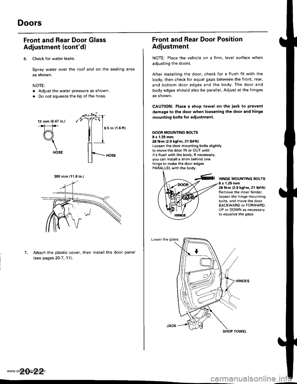
6. Check for water leaks.
Spray water over the roof and on the sealing area
as snown.
NOTE:
. Adjust the water pressure as shown.
. Do not soueeze the tio of the hose.
12 mm {0.47 in.l
#
(r\"1
HOSE
-"'*r"i
,'r)"f
tl
0.5 m (1.6 ftl
7. Attach the plastic cover, then install the door panel
(see pages 20-7, 'l 1),
20-22
..-
300 mm 111.8 in.)
Front and Rear Door Position
Adjustment
NOTE: Place the vehicle on a firm, level surface when
adiusting the doors.
After instailing the door, check for a flush fit with the
body, then check lor equal gaps between the front, rear.
and bottom door edges and the body. The door and
body edges should also be parallel. Adjust at the hinges
as shown.
CAUTION: Placa a shop towel on the iack to prevent
damage to the door when loosening the door and hinge
mounting bolts lor adiustment.
DOOR MOUNTING BOLTSI x 1.25 mm28 N.m 12.9 kgtr.m, 21 lbI.ftlLoosen the door mounting bolrs slighrlyto movethe door lN or OUT untilit's flush with the bodv. lf necessary,you can installa shim behind onehinge to make the door edgesPARALLEL with the bodv.
HINGE MOUNTING BOLTS8 x 1.25 mm28 N,m 12.9 kgt.m. 21 lbl.ftlRemove the inner fender,loosen the hinge mountingbolts, and move the doorBACKWARD or FORWARD,UP or DOWN as necessaryto equalize the gaps.
Lower the glass.
www.emanualpro.com
Page 1016 of 1395
22.
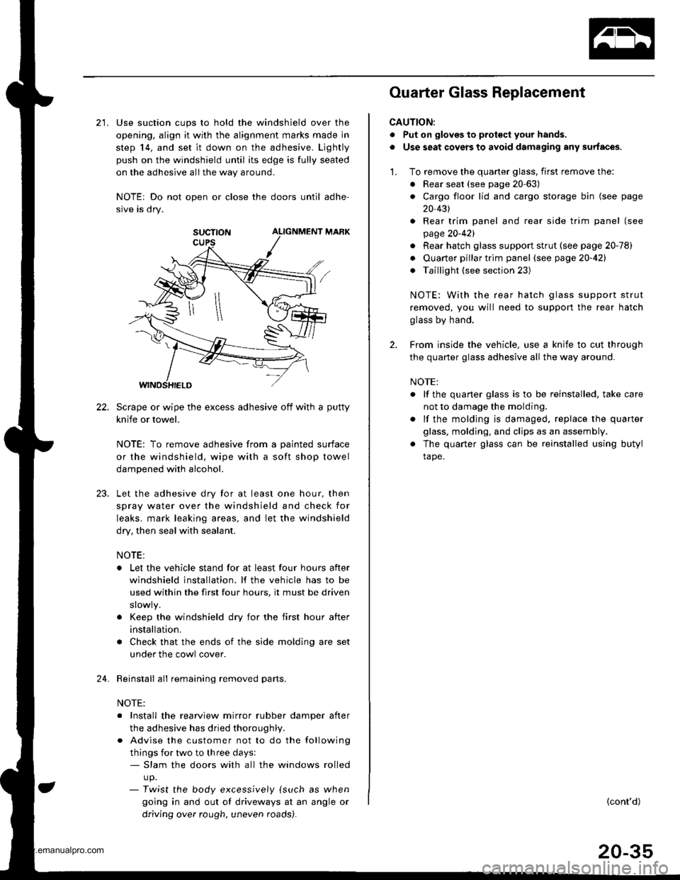
21. Use suction cups to hold the windshield over the
opening, align it with the alignment marks made in
step 14, and set it down on the adhesive. Ljghtly
push on the windshield until its edge is fully seated
on the adhesive all the way around.
NOTEr Do not open or close the doors until adhe-
sive is dry.
SUCTTON ALIGNMENT MARK
Scrape or wipe the excess adhesive off with a putty
knife or towel.
NOTE: To remove adhesive from a painted surface
or the windshield, wipe with a soft shop towel
dampened with alcohol.
Let the adhesive dry for at least one hour, then
spray water over the windshield and check for
leaks. mark leaking areas, and let the windshield
dry, then seal with sealant.
NOTE:
. Let the vehicle stand for at least four hours after
windshield installation. lf the vehicle has to be
used within the first four hours, it must be driven
. Keep the windshield dry for the first hour after
installation.
. Check that the ends of the side molding are set
under the cowl cover.
Reinstall all remaining removed parts.
NOTE:
. Install the rearview mirror rubber damper after
the adhesive has dried thoroughl,.
. Advise the customer not to do the following
things for two to three days:- Slam the doors with all the windows rolled
up.- Twist the body excess,vely {such as when
going in and out of driveways at an angle or
driving over rough. uneven roads).
24.
Ouarter Glass Replacement
CAUTION:
. Put on gloves to prot€ct your hands.
. Use seat covers to avoid damaging any surfaces.
1. To remove the quarter glass, first remove the:
. Rear seat (see page 20-63)
. Cargo floor lid and cargo storage bin (see page
20 431
. Rear trim panel and rear side trim panel (see
page 20-421
. Rear hatch glass support strut (see page 20-78)
. Ouarter pillar trim panel (see page20-421
. Taillight (see section 23)
NOTE: With the rear hatch glass support strut
removed, you will need to support the rear hatch
glass by hand.
2. From inside the vehicle, use a knife to cut through
the quarter glass adhesive all the way around.
NOTE:
. lf the quaner glass is to be reinstalled, take care
not to damage the molding.
. lf the molding is damaged. replace the quarter
glass, molding, and clips as an assembly.
. The quarter glass can be reinstalled using butyl
tape.
(cont'd)
20-35
www.emanualpro.com
Page 1022 of 1395
Removal and Installation
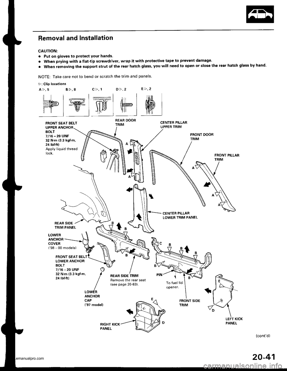
CAUTION:
. Put on gloves to protect your hands,
. When prying with a tlat-tip screwdrivel, wrap it with protective tape to prevent damage.
. When removing the support strut of the rear hatch glass, you will need to open or close the rear hatch glass by hand.
NOTE: Take care not to bend or scratch the trim and panels.
>: Clio locations
a>,5c>, 1o>.2e>,2B >,8
UPPERBOLT7/16 - 20 UNF32 N.m {3.3 kgf.m,24 rbt.ft)Apply liquid thread
CENTER PILLARLOWER TRIM PANEL
LOWERANCHOBCOVER('98 00 models)
{cont'd)
I l_lss-l , | 'rrl
elElw"lel sl
FRONT SEAT BELT
FRONT SEAT BELLOWER ANCHORBOLT7/15 - 20 UNF32Nm(3.3kgf.m,24 tbt.ftl
ANCHORCAP('97 model)
REAR DOORTRIM
REAR SIDE TRIMtlemove the rear seat(see page 20 63).
REAR SIDE
20-41
www.emanualpro.com
Page 1023 of 1395
Interior Trim
@wt we@M
REAR SIOETRIM PANELRemove the reat seat(see page 20-63).
FCONNECTOR
2
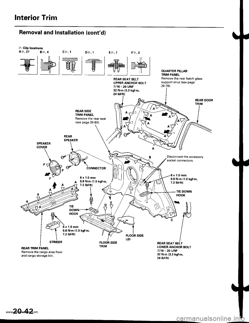
OUARTER PILLARTNIM PANELRemove the rear hatch glasssupport strut (see page20-741.
Removal and Installation (cont'd)
>i Clip loc.tionsa>,21B>,4c>, 1E>. !F >,3D>, 1
Disconnect the accessorysocket connectors,
9.8 N.m (1.0 kgf.m,1.2lbt-lrl
5x1.0mm6x1.0mm9.8 N.m (1.0 kgtm,7.2 tbf ftl
TIE DOWNHOOK
6x1.0mm
TIEoowNHOOK
v
O\A
D
REAR SEAT BELTLOWER ANCHOR EOLT7/16 - 20 UNF32 N.m {3.3 kgt.m,24 tbl.frl
9.8 N.m (1.0 kgt m,7.2 tbf.ft)
REAR TRIM PANELRemove the cargo area floorand cargo slorage bin.
20-42
REAN SEAT BELTUPPER ANCHOR BOLT7/16-20 UNF32 N.m {3.3 kgt.m,24 rbt.ft)
REAR DOOR
REAR
ffi
STRIKER
www.emanualpro.com
Page 1025 of 1395
lnterior Trim
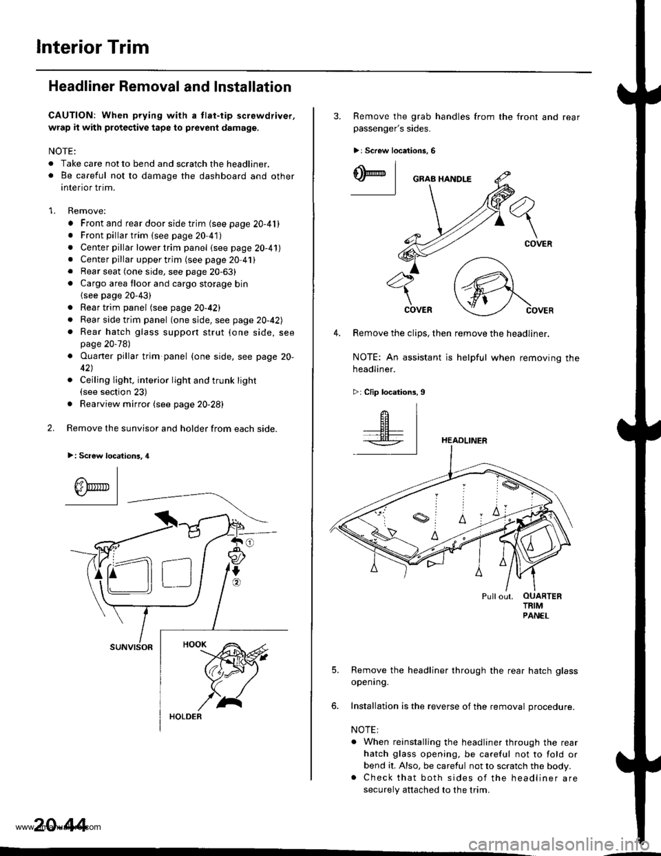
Headliner Removal and Installation
CAUTION: When prying with a tlat-tip screwdriver,
wrap it with protective tape to prevent damage.
NOTE:
. Take care not to bend and scratch the headliner.o Be careful not to damage the dashboard and other
interior trim.
1. Remove:
. Front and rear door side trim (see page 20-41). Front pillartrim (see page 20-41)
. Center pillar lower trim panel (see page 20-41). Center pillar upper trim (see page 20 41). Rear seat (one side, see page 20-63). Cargo area floor and cargo storage bin
{see page 20-43)
. Rear trim panel (see page 20-421
. Rear side trim panel (oneside, see page 20-42l,
. Rear hatch glass support strut (one side, seepage 20-78)
. Ouaner pillar trim panel {one side, see page 20-
42)
. Ceiling light, interior light and trunk light(see section 23)
. Rearview mirror (see page 20-28)
2. Remove the sunvisor and holder from each side.
>: Scaew location3, 4
I
A\"r- |Yr* || -
suNvtsoR
20-44
3. Remove the grab handles from
passenger's sides.
>r Screw locations, 6
the front and rear
ry_l
COVER
4. Remove the clips, then remove the headliner.
NOTE: An assistant is helpful when removing the
headliner.
>: Clip locations,9
HEADLINER
Pullout. OUARTERTRIMPANEL
5. Remove the headliner through the rear hatch glass
openrng.
6. Installation is the reverse of the removal procedure.
NOTE:
. When reinstalling the headliner through the rear
hatch glass opening, be careful not to fold or
bend it, Also, be careful not to scratch the body.. Check that both sides of the headliner are
securely attached to the trim.
www.emanualpro.com
Page 1075 of 1395
Openers
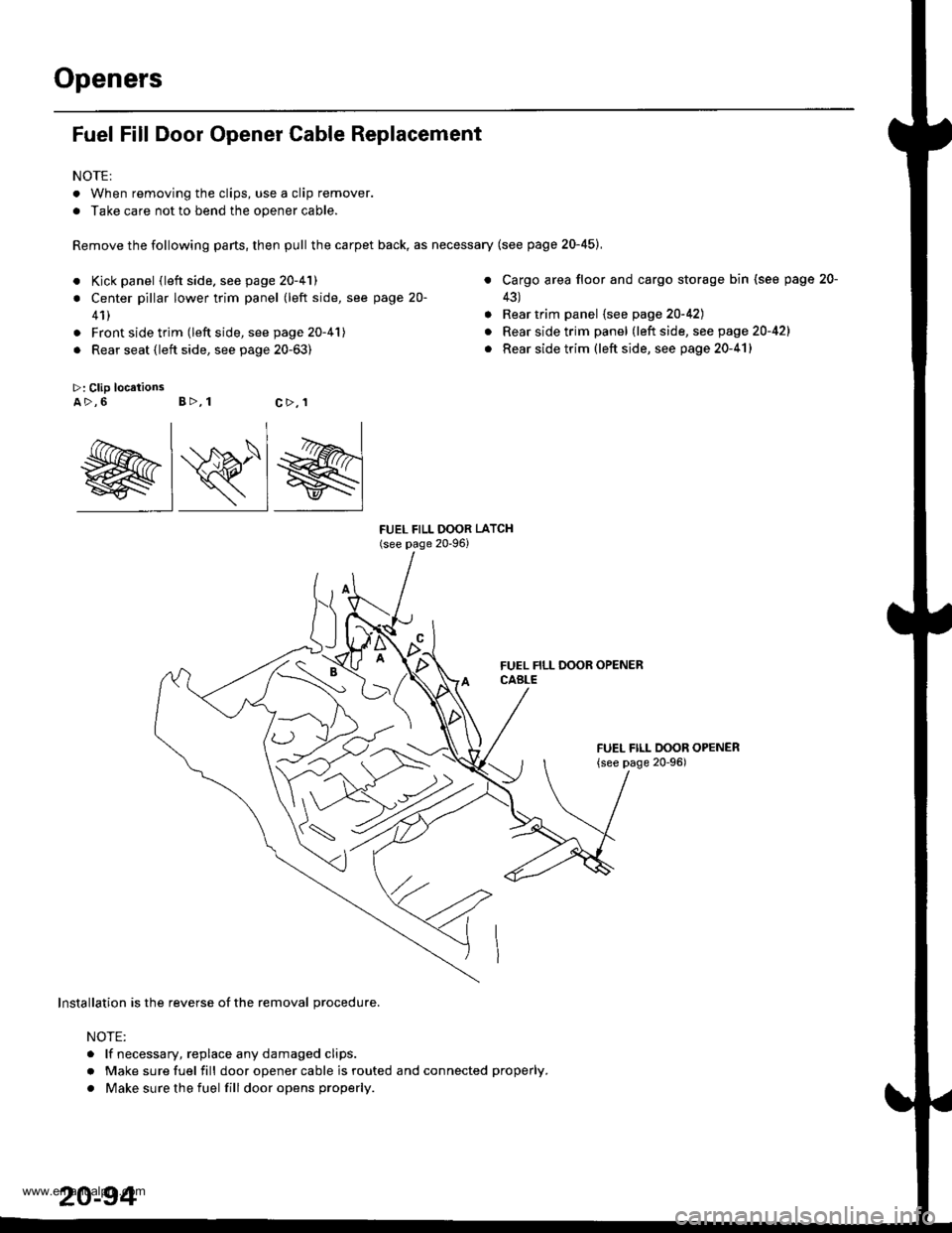
Fuel Fill Door Opener Cable Replacement
NOTE:
. When removing the clips, use a clip remover.
. Take care not to bend the opener cable.
Remove the following parts, then pull the carpet back, as necessary (see page 20-45),
a
>: Clip locationsA>,6 B>, 1
a
a
FUEL FILL OOOR LATCH(see page 20-96)
Kick panel (left side. see page 20-41)
Center pillar lower trim panel (left side, see page 20-
41)
Front side trim (left side, see page 20-41)
Rear seat (left side, see page 20-63)
Cargo area floor and cargo storage bin (see page
43)
Rear trim panel {see page 20-42)
Rear side trim panel (left side, see page 20-421
Rear side trim (left side, see page 20-41)
FUEL FILL DOOR OPENER
{see page 20-96)
20-
c>,1
@lRlg
Installation is the reverse of the removal procedure.
NOTE:
. lf necessary, replace any damaged clips.
r Make sure fuel fill door opener cable is routed and connected properly.
. Make sure the fuel fill dooropens properly.
www.emanualpro.com
Page 1077 of 1395
Openers
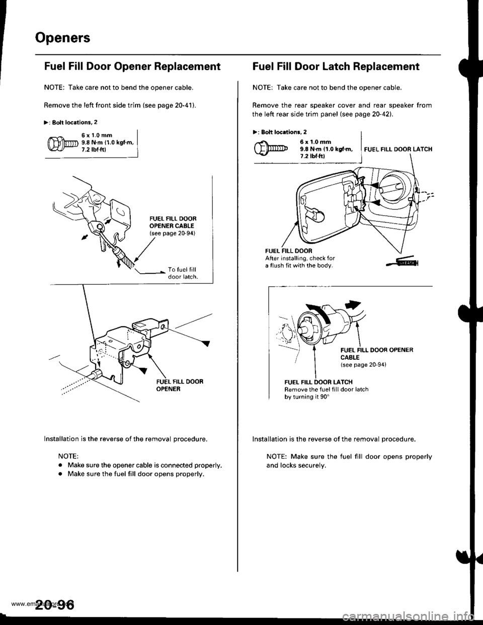
Fuel Fill Door Opener Replacement
NOTE: Take care not to bend the opener cable.
Remove the left front side trim (see page 20-41).
>: Bolt locstions.2
5x1.0mm9.8 N.m (1.0 kgf.m,7.2 tbt.ftl
FUEL FILL DOOROPENER CABLE(see page 20-94)
Installation is the reverse of the removal procedure.
NOTE:
. Make sure the opener cable is connected properly.
. Make sure the fuel fill door opens properly,
20-96
Fuel Fill Door Latch Reolacement
NOTE: Take care not to bend the opener cable.
Remove the rear speaker cover and rear speaker from
the left rear side trim panel (see page 20-42).
>: Boh locdions, 2
6x1.0mm9.8 N.m (1.0 kgf.m,7.2 tbf.ft)FUEL FILL DOOR LATCH
FUEL FILL DOORAfter installing, check fora flush fit with the body.
CAELE(see Page
LATCH
DOOR OPENER
20,94)
FUEL
FUEL FILLRemove the fuel fill door latchby turning it 90'
Installation is the reverse of the removal procedure.
NOTE: Make sure the fuel fill door opens properly
and locks securely.
www.emanualpro.com
Page 1101 of 1395
Self-diagnosis Function
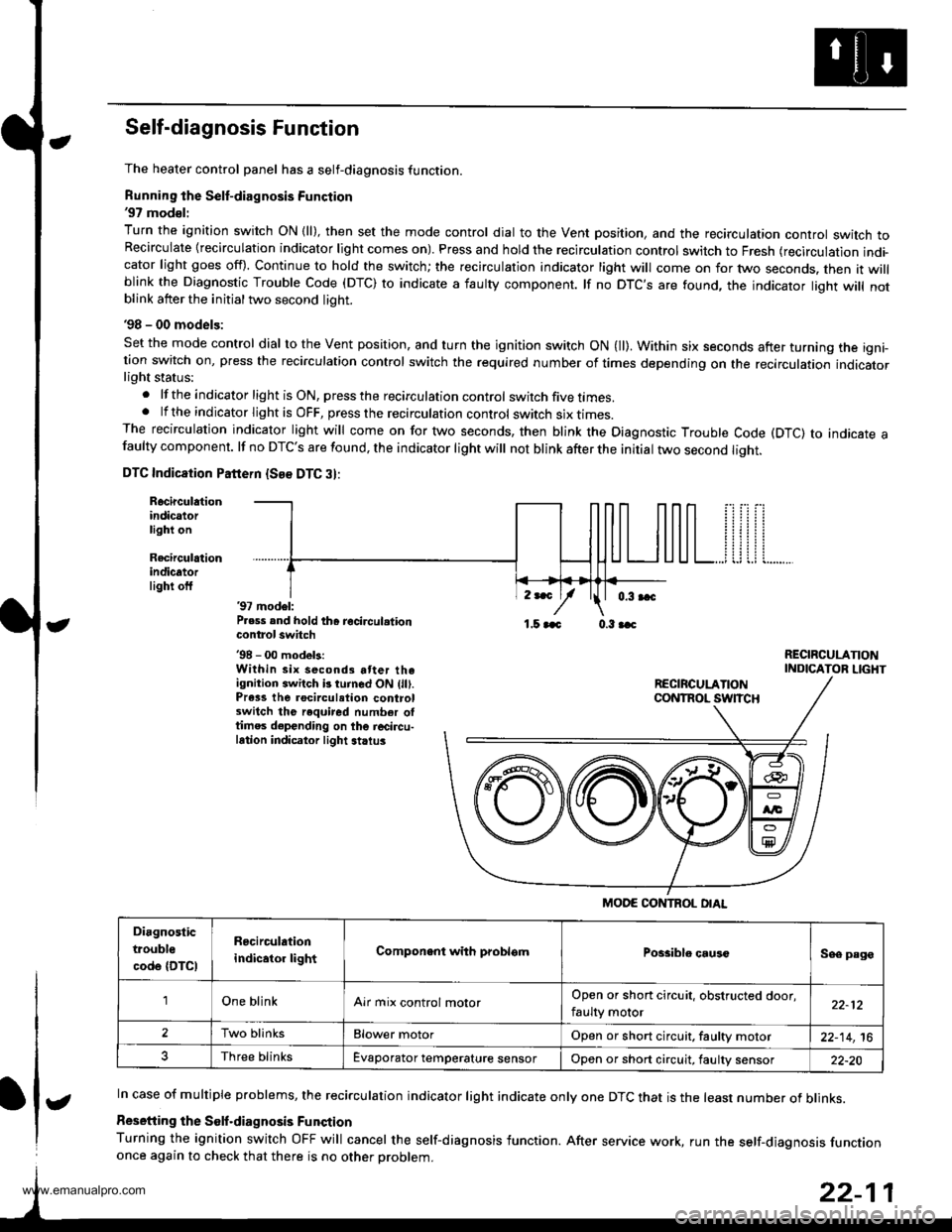
The heater control panel has a self-diagnosis function.
Running the Self-diagnosis Function'97 mod€l:
Turn the ignition switch ON {ll), then set the mode control dial to the Vent position, and the recirculation controt switch toRecirculate {recirculation indicator light comes on). Press and hold the recirculation control switch to Fresh (recirculation indi-cator light goes off). Continue to hold the switch; the recirculation indicator light will come on for two seconds. then it willblink the Diagnostic Trouble Code (DTC) to indicate a iaulty component. lf no DTC'S are found, the indicator liqht will notblink atter the initial two second light.
'98 - 00 models:
Set the mode control dial to the Vent position, and turn the ignition switch ON (ll). Within six seconds after turning the igni-tion switch on, press the recirculation control switch the required number of times depending on the recirculation indicatorlight status:
.lftheindicatorlightisON,presstherecirculationcontrol switch five times..lftheindicatorlightisOFF,presstherecirculationcontrol switch six I|mes.The recirculation indicator light will come on for two seconds, then blink the Diagnostic Trouble Code (DTC) to indicate afaulty component. lf no DTC'S are found, the indicator light will not blink after the initial two second liqht.
DTC Indicaiion Pattern {See DTC 3}:
Rocirculationindicatorlight on
Recirculrtionindicatorlighi off'97 model:P.ess and hold th6 recircul.tioncontrol switch'98 - 00 modek:Within six second3 atter theignition switch b turned ON (lll.Prass the rocirculation controlswitch the required number oltimes depending on the r6circu-lation indicator light striu3
,r*
/1.5 aaa 0.3 aac
RECIRCULANONINDICATOR LIGHT
In case of multiple problems, the recirculation indicator light indicate only one DTC that is the least number of blinks.
Resetiing the Solf.diagnosis Funqtion
Turning the ignition switch OFF will cancel the self-diagnosis function. After service work, run the self-diaqnosis functiononce again to check that there is no other Droblem.
MODE CONTROL OIAL
Diagnostic
trouble
code {DTCI
R6circulation
indicator lightComponent with problsmPossiblo causcSee page
'lOne blinkAir mix control molorOpen or short circuit, obstructed door,
faulty motor22-12
2Two blinksElower motorOpen or short circuit, faultv motor22-14,16
Three blinksEvaporator temperature sensorOpon or short circuit, faulty sensor22-20
t
www.emanualpro.com
Page 1102 of 1395
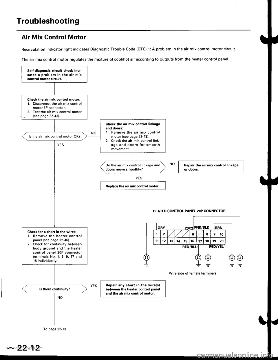
Troubleshooting
Air Mix Control Motor
Recirculation indicator light indicates Diagnostic Trouble Code (DTC) 1: A problem in the air mix control motor circuit.
The air mix control motor regulates the mixture of cool/hot air according to outputs from the heater control panel.
Selt-diagnosis circuit check indi-cates a Droblem in the air mixcontrol motor circuil.
Chock the air mix control moior:1. Disconnect the air mix controlmotor 5P connector,2, Test the air mix control motor(see page 22-43).
Check the air mix control linkagoand doors:1. Remove the air mix controlmotor (see page 22'43).2. Check the air mix control linkage and doors for smooth
ls the air mix control motor OK?
Do the air mix control linkage anddoors move smoothly?
Reolacelhe air mix conlrol motor.
Check Ior a short in the wires:1- Remove the heater controlpanel (see page 22-46).2. Check tor continuity betweenbody ground and the heatercontrol panel 20P connectorterminals No. 1, 6, 9, 17 and18 individually.
Ropair any short in the wire(s)betwoon th. heater co.rtrol panel
and the air mix conlrol motor.
HEATER CONTROL PANEL 2OP CONNECTOR
PNK/BLK
RED/BLU
Wire side of female terminals
To page 22-13
www.emanualpro.com
Page 1105 of 1395
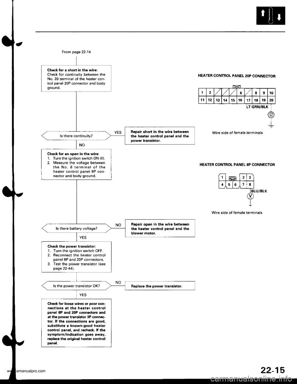
From page 22-14
Chock for a short in the wire:Check tor continuity between theNo. 20 terminal of the heater con'trol panel 20P connector and bodyground,
R.p.ir short in the wire betwoenth. herter control Denel snd theoowor tranSastor.
Check to. an open in the wire:1. Turn the ignition swilch ON (ll).
2. Measure the voltage betweenthe No. I terminal of theheater control panel 8P con-nector and body ground.
Repair opan in the wire betwaentho heatsr cont.ol o.nel and theblower motor.ls there battery voltage?
Chock th6 power iransistor:1. Turn the ignition switch OFF.2. Reconnect the heater controlpanel 8P and 20P connectors.3. Test the power transistor (seepage 22 44).
ls the power transistor OK?
Chec* for loo3e wires or Door oon-neclions at the heater controlpanel 8P and 20P connoctors andat lhe power tran3istor 3P connec-tor. lf lhe connectiorc are good,substituta , known-good hoatercontrcl pan6l, and r€check. ll thesymptom/indication goes away.replecg th6 original heater controloanel.
HEATER CONTROL PANEL 2OP CONNECTOR
2,/1,/l/68910
1112131a151617181920
LT GRN/BLK
o
Wire side of female terminals
HEATER CONTROL PANEL 8P CONNECTOR
BLU/8LK
Wire side of female terminals
1
4678
22-15
www.emanualpro.com