Front shaft HONDA CR-V 1999 RD1-RD3 / 1.G Owner's Manual
[x] Cancel search | Manufacturer: HONDA, Model Year: 1999, Model line: CR-V, Model: HONDA CR-V 1999 RD1-RD3 / 1.GPages: 1395, PDF Size: 35.62 MB
Page 823 of 1395
![HONDA CR-V 1999 RD1-RD3 / 1.G Owners Manual
Front Driveshafts
parts with solvent.
o *4@] :Thoroughly pack the inboard and outboard joints and both joint boots with the joint grease included in the
new driveshaft set.. The98 Canada model andal HONDA CR-V 1999 RD1-RD3 / 1.G Owners Manual
Front Driveshafts
parts with solvent.
o *4@] :Thoroughly pack the inboard and outboard joints and both joint boots with the joint grease included in the
new driveshaft set.. The98 Canada model andal](/img/13/5778/w960_5778-822.png)
Front Driveshafts
parts with solvent.
o *4@] :Thoroughly pack the inboard and outboard joints and both joint boots with the joint grease included in the
new driveshaft set.. The'98 Canada model andall '99 - 00 models use a TPE (Thermoplastic Polyester E lastomer) outboard joint boot.
Use the ear clamp type boot band in the outboard boot set.
Grease quantity:
Inboard Joint: All models 120 - 130 g (i1.2 - 4.6 oz)
Left inboard joint splines (Al: 0.5 - 1.0 g (0.018 - 0.035 oz)
Outboard Joint: '97 model and'98 USA model 130 - 140 g (4.6 -,1.9 oz)'98 Canada model and all '99 - 0O models 140 - 150 g 14.9 - 5.3 oz)
Reassembly
Note these items during reassembly
. Clean the disassembled parts with solvent, anddry them thoroughly with compressed air. Do not wash the rubber
INBOARO JOINT
SPIOERINBOARD BOOT
SET RINGReplace.
LEFT INBOAROJOINT
SPLINES: (Al-6rPack cavity with grease.
wtn grease.
BANDS
DYNAMIC DAMPER
STOP RINGReplace.
OUTBOARD BOOT
EAR CLAMPReplace.
ITPE)*I
-611
-/ Pack cavity with grease.
DOUELEReplace.BAND+'BAND*1
__G1Pack cavitywrtn grease.
OUTBOARD BOOT*'(RUBBERI
-GrjPack cavity*l: '98 Canada models, all '99-00models
*2: '97 - 98 models (except'98 Canada model)
16-8
wtrn grease.
www.emanualpro.com
Page 825 of 1395
Front Driveshafts
Reassembly {cont'd)
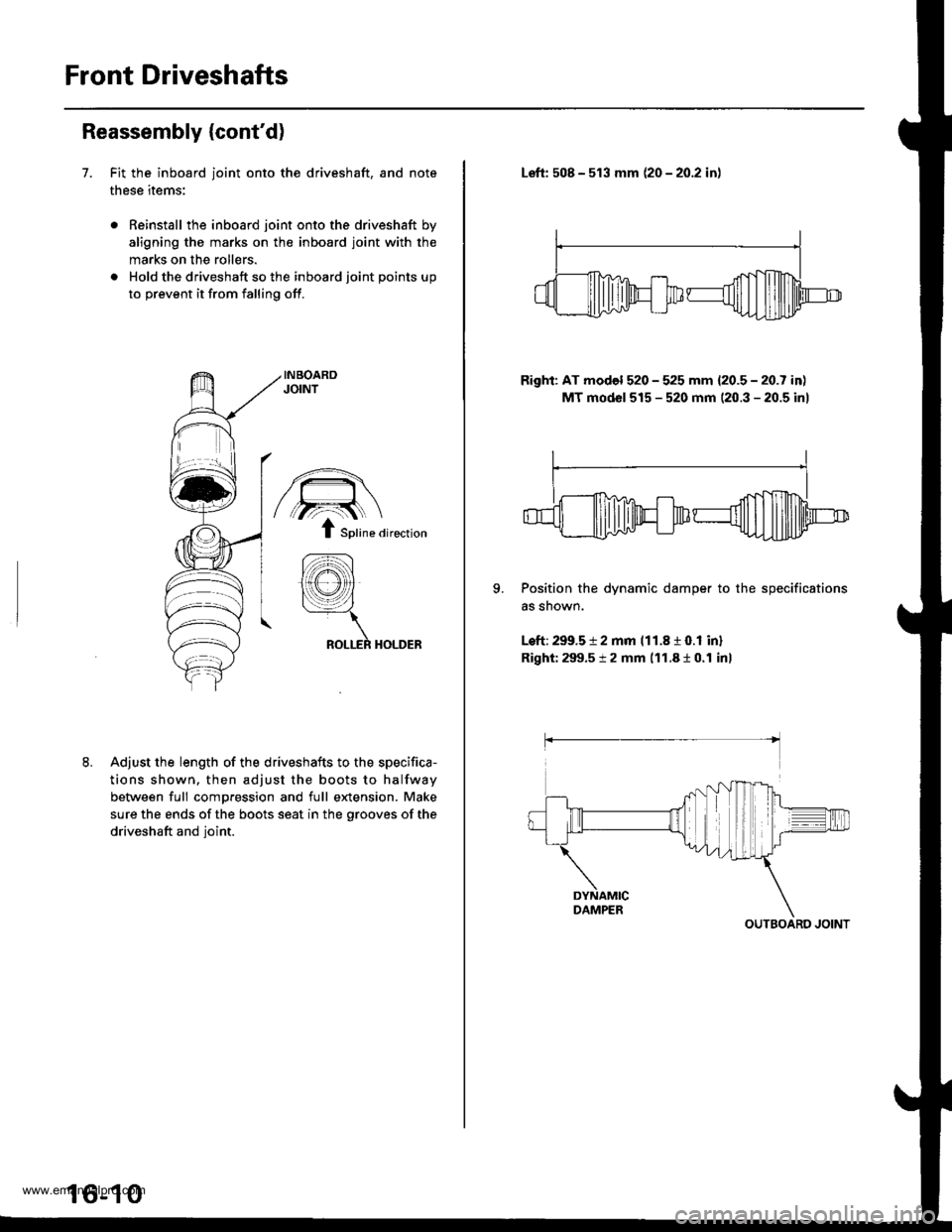
7. Fit the inboard joint onto the driveshaft, and note
these items:
Reinstall the inboard joint onto the driveshaft by
aligning ths marks on the inboard joint with the
marks on the rollers.
Hold the driveshaft so the inboard joint points up
to prevent it from falling off.
Adjust the length of the driveshafts to the specifica-
tions shown. then adjust the boots to halfway
between full compression and full e)dension. Make
sure the ends of the boots seat in the grooves of the
driveshaft and Ioint.
/€\
/,?:..�{ \
t Sptine airection
lffi
tYl:\
ROLLER HOLDER
16-10
Left: 508 - 513 mm 120 - 2O.2 inl
Right: AT model 520 - 525 mm {20.5 - 20.7 in)
MT mod6l 515 - 520 mm (20.3 - 20.5 inl
II
-flm+dm@
9. Position the dynamic damper to the specifications
as snown.
Left: 299.5 t 2 mm 111.8 r O.l inl
Right: 299.5 t 2 mm 111.810.1 inl
OUTBOARO JOINT
www.emanualpro.com
Page 827 of 1395
Front Driveshafts
Reassembly (cont'd)
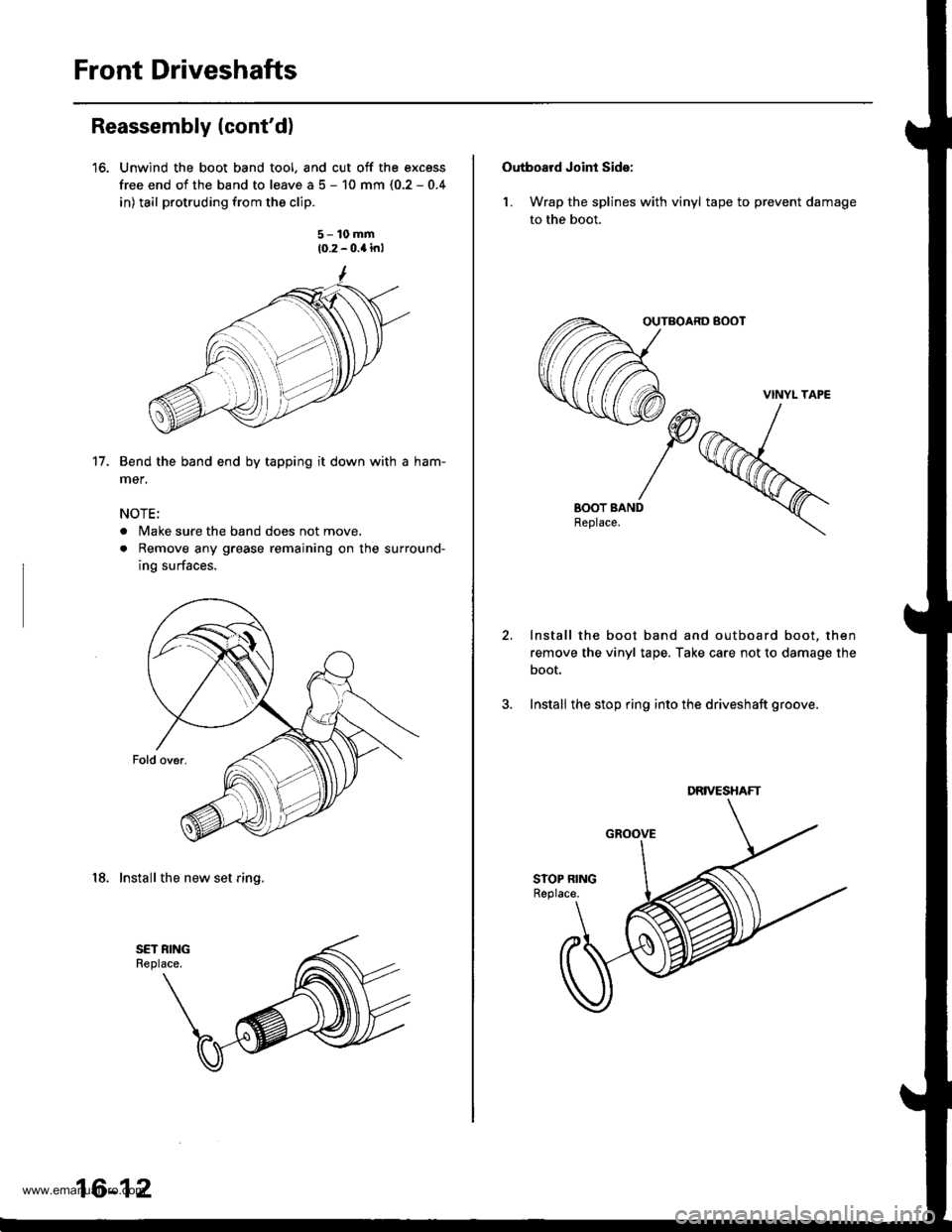
16. Unwind the boot band tool. and cut off the excess
free end of the band to leave a 5 - 10 mm (0.2 - 0.4
in) tail protruding from the clip.
5- 10 mm
10.2 - 0.4 in,
Bend the band end by tapping it down with a ham-
mer,
NOTE;
. Make sure the band does not move,
. Remove any grease remaining on the surround-
ing surfaces.
18, Install the new set ring.
17.
16-12
Outbosrd Joint Sids:
1. Wrap the splines with vinyl tape to prevent damage
to the boot.
OUTBOARD BOOT
2, Install the boot band and outboard boot, then
remove the vinyl tape. Take care not to damage the
boot.
3. Install the stop ring into the driveshaft groove.
VINYL TAPE
DRIVESHAFT
www.emanualpro.com
Page 829 of 1395
Front Driveshafts
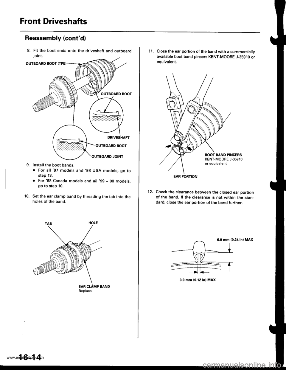
8. Fit the boot ends onto the driveshaft and outboard
lornt.
OUTBOARD BOOT fiPE)
OUTBOARD BOOT
OUTBOARD BOOT
Reassembly (cont'd)
Install the boot bands,
. For all '97 models and'98
step 13.
. For'98 Canada models andgo to step 10.
OUTBOARD JOINT
USA models, go to
all '99 - 00 models,
10. Set the ear clamp band by threading the tab into theholes of the band.
16-14
11. Close the ear portion of the band with a commercially
available boot band pincers KENT-MOORE J-35910 or
equivalent.
BOOT BAND PINCERSKENT.MOORE J-35910or equivalent
12.Check the clearance between the closed ear Dortionof the band, lf the clearance is not within the stan-dard, close the ear portion of the band further.
6.0 mm 10.24 in) MAX
3.0 mm {0.12 in} MAX
EAR PORTION
www.emanualpro.com
Page 831 of 1395
Front Driveshafts
Reassembly (cont'dl
18.
19.
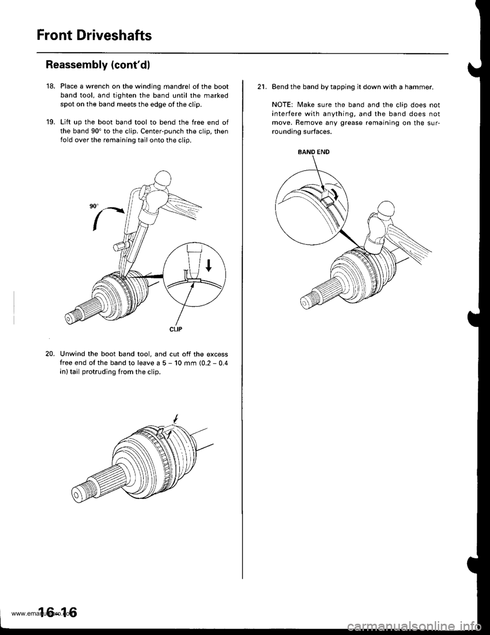
Place a wrench on the winding mandrel of the boot
band tool, and tighten the band until the marked
spot on the band meets the edge of the clip.
Lift up the boot band tool to bend the free end of
the band 90" to the clip. Center-punch the clip, then
fold over the remaining tail onto the clip.
Unwind the boot band tool. and cut off the excess
free end of the band to leave a 5 - 10 mm (0.2 - 0.4
in) tail protruding from the clip.
20.
CLIP
16-16
21, Bend the band by tapping it down with a hammer.
NOTE: Make sure the band and the clip does not
interfere with anything, and the band does not
move, Remove any grease remaining on the sur-
rounding surfaces.
BAND END
www.emanualpro.com
Page 832 of 1395
Front Driveshafts
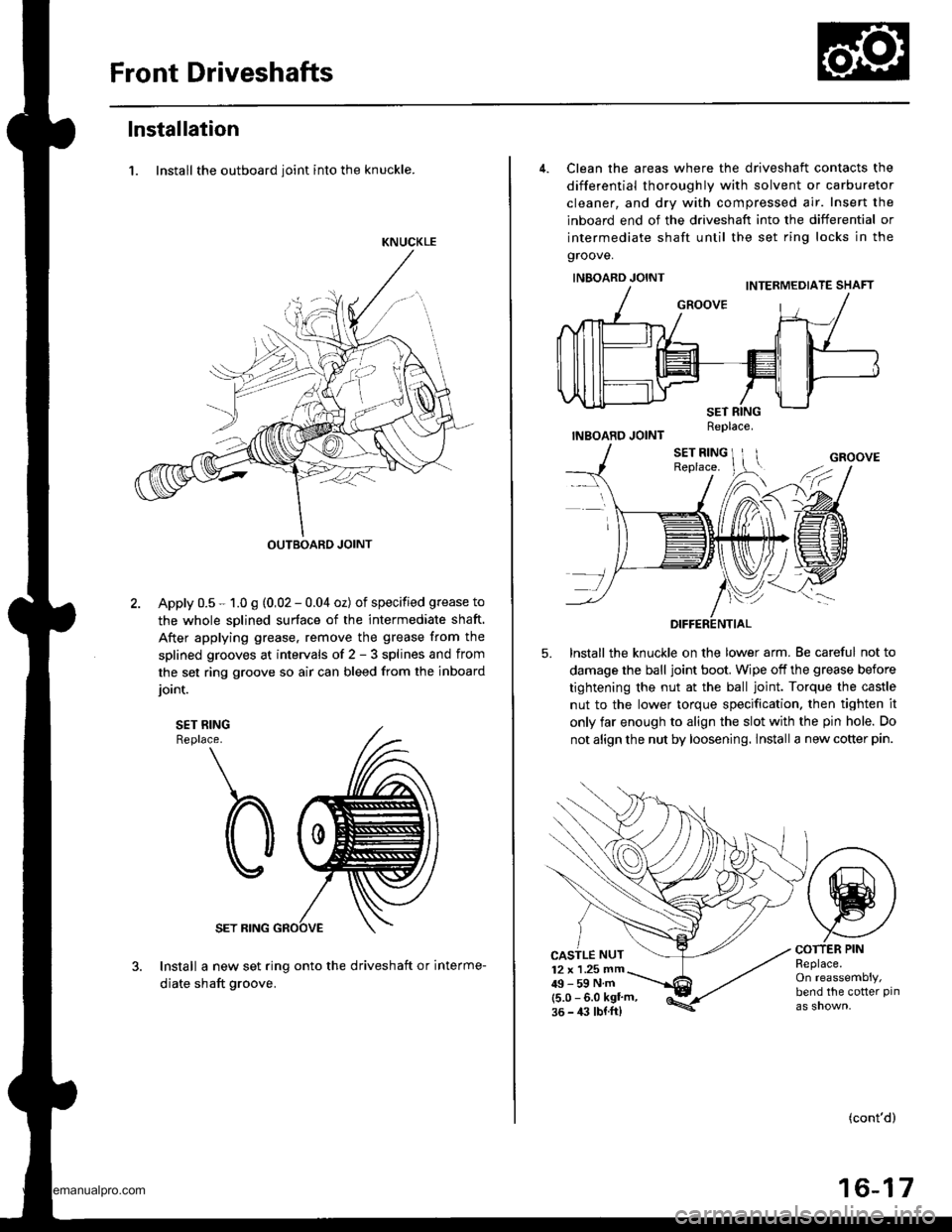
lnstallation
1. Install the outboard ioint into the knuckle.
KNUCKLE
OUTBOARD JOINT
Apply 0.5 - 1.0 g (0,02 - 0.04 oz) of specified grease to
the whole sDlined surface of the intermediate shaft.
After applying grease. remove the grease from the
splined grooves at intervals of 2 - 3 splines and from
the set ring groove so air can bleed from the inboard
ioint.
SET RINGReplace.
SET RING
Install a new set ring onto the driveshaft or interme-
diate shaft groove.
4. Clean the areas where the driveshaft contacts the
differential thoroughly with solvent or carburetor
cleaner, and dry with compressed air. Insert the
inboard end of the driveshaft into the differential or
intermediate shaft until the set ring locks in the
groove.
INBOARD JOINT
INBOARD JOINT
lnstall the knuckle on the lower arm. Be careful not to
damage the ball joint boot. Wipe off the grease before
tightening the nut at the ball joint. Torque the castle
nut to the lower torque specification. then tighten it
only far enough to align the slot with the pin hole. Do
not align the nut by loosening. lnstall a new cotter pin.
5.
CASTLE NUT12 x 1 .25 mm49-59Nm(5.0 - 6.0 kgl'm,36 - 4:l lbl.ft)
COTTER PINReplace.On reassembly,bend the cotter pin
(cont'd)
16-17
Replace.
www.emanualpro.com
Page 833 of 1395
Front DriveshaftsIntermediate Shaft
Installation {cont'd}
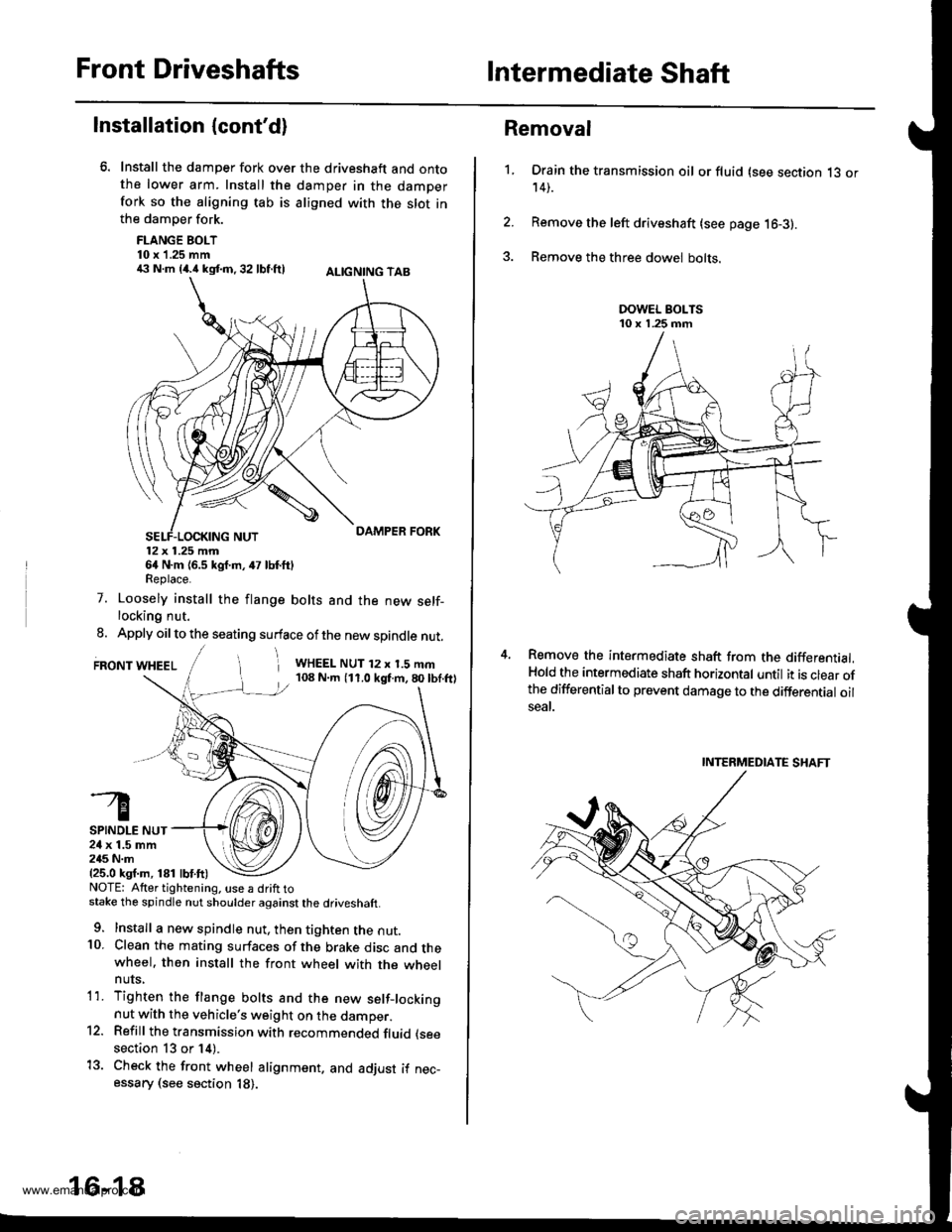
Install the damper fork over the driveshaft and ontothe lower arm. Install the damper in the damperfork so the aligning tab is aligned with the slot inthe damper fork.
FLANGE BOLT10 x 1.25 mm€ N.m {4.i1kst.n,32 lbf.ftl ALtcNtNG TAB
12x 1.25 mm64 N.m {6.5 kgf.m, 47 lbf.ftlReplace.
7. Loosely install the flange bolts and the new self-locking nut.
8. Apply oil to the seating surface of the new spindle nut.
FRONT WHEELi WHEEL NUT 12 x 1.5 mm108 N.m (11.0 kgf.m,80lbf.ftl
SPINDLE NUT24 x 1.5 mm245 N.m{25.0 ksf.m, 181 lbf.ft)NOTE: Atter tightening. use a drift tostake the spindle nut shoulder against the driveshaft.
9. Install a new spindle nut, then tighten the nut.10. Clean the mating surfaces of the brake disc and thewheel. then install the front wheel with the wheelnuts,
1'1. Tighten the flange bolts and the new setf-lockingnut with the vehicle's weight on the damper.12. Refill the transmission with recommended fluid (see
section 13 or 14).
13. Check the front wheel alignment. and adjust if nec-essary (see section 18).
16-18
1.
Removal
Drain the transmission oil or fluid (see section 13 or14).
Remove the left driveshaft (see page 16-3).
Remove the three dowel bolts.
Remove the intermediate shaft from the differential.Hold the intermediate shaft horizontal until it is clear ofthe differentialto prevent damage to the differential oilseal.
INTERMEDIATE SHAFT
www.emanualpro.com
Page 841 of 1395
Rear Driveshafts
Reassembly (cont'd)
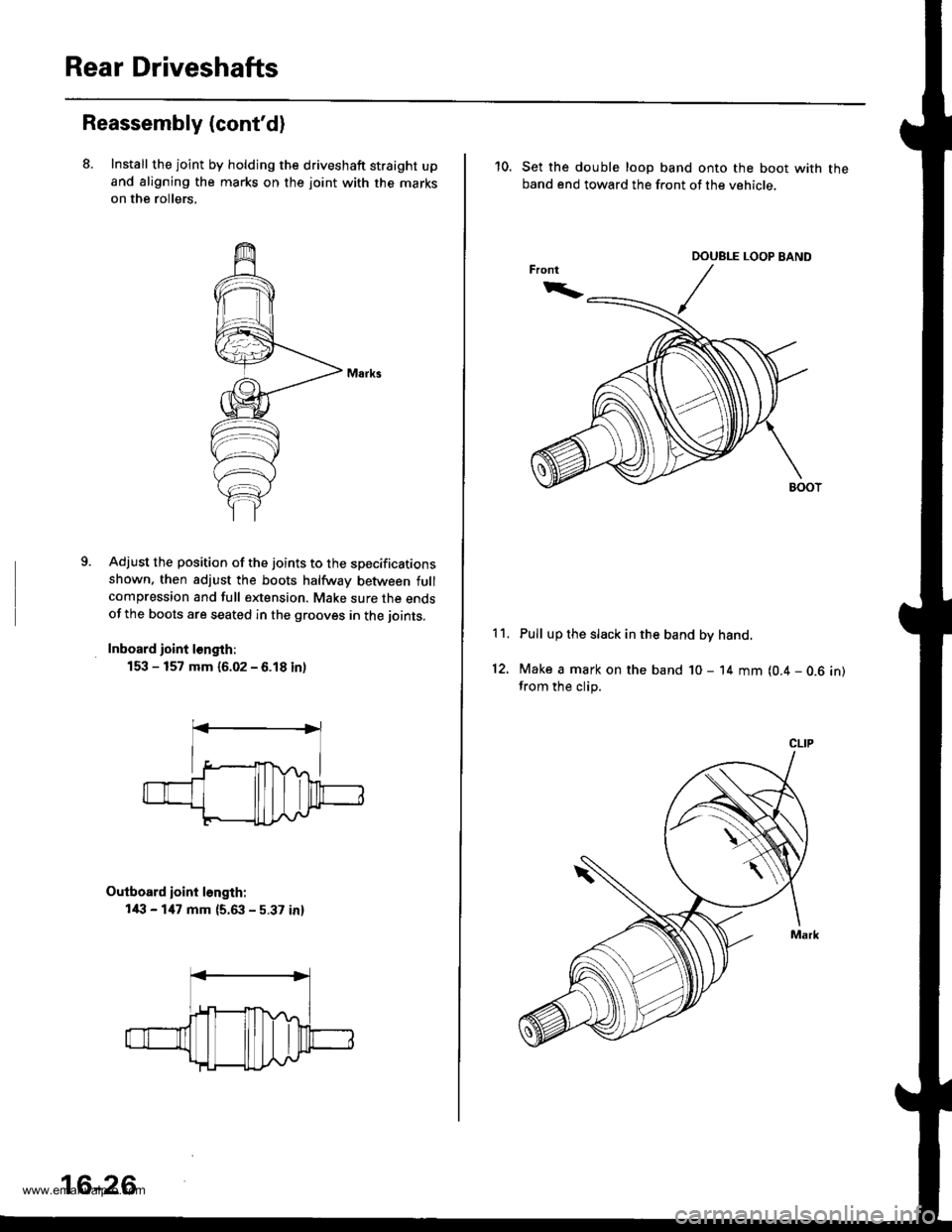
8. Install the joint by holdjng the driveshaft straight upand aligning the marks on the joint with the marks
on the rollers,
9.Adjust the position of the joints to the specificationsshown. then adjust the boots halfway between fullcompression and full extension. Make sure the endsof the boots are seated in the grooves in the joints.
Inboard ioint l€ngth:
153 - 157 mm {6.02 - 6.18 inl
Outboard ioint l6ngth:
l/l:' - 147 mm {5.63 - 5.37 in}
16-26
10. Set the double loop band onto the boot with theband end toward the front of the vehicle,
Pull up the slack in the band by hand.
Make a mark on the band 10 - 14 mm (0.4 - 0.6 in)from the clip.
11.
12.
CLIP
www.emanualpro.com
Page 863 of 1395
Steering Wheel
Removal
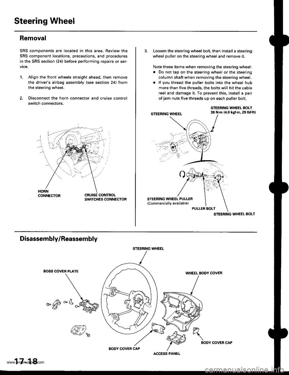
SRS components are located in this area. Review the
SRS component locations, precautions, and procedures
in the SRS section (24) before performing repairs or ser-
vice.
1. Align the front wheels straight ahead. then remove
the driver's airbag assembly (see section 24) from
the steering wheel.
2. Disconnect the horn connector and cruise control
switch connectors.
CONTROLSWITCHES CONNECTOR
3. Loosen the steering wheel bolt, then install a steering
wheel puller on the steering wheel and remove it.
Note these items when removing the steering wheel:
. Do not tap on the steering wheel or the steering
column shaft when removing the steering wheel.
. lf you thread the puller bolts into the wheel hub
more than five threads, the bolts will hit the cable
reel and damage it. To prevent this, install a pair
of jam nuts five threads up on each puller bolt.
STEERING WHEEL BOLT39 N.m 14.0 kgt.m,29 lbtftl
STEERING WHEEL EOLT
Disassembly/Reassembly
EOSS COVER PLATE
_^M
STEERING WHEEL
WHEEL BODY COVER
17-18
@,
ACCESS PANEL
h"\
BODYCOVER CAP
www.emanualpro.com
Page 864 of 1395
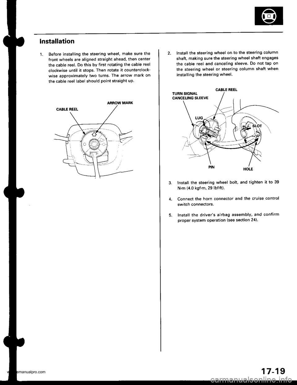
lnstallation
1. Before installing the steering wheel, make sure the
front wheels are aligned straight ahead, then center
the cable reel. Do this by first rotating the cable reel
clockwise until it stops. Then rotate it counterclock-
wise approximately two turns. The arrow mark on
the cable reel label should point straight up.
ARROW MARK
2. Install the steering wheel on to the steering column
shaft, making sure the steering wheel shaft engages
the cable reel and canceling sleeve. Do not tap on
the steering wheel or steering column shatt when
instailing the steering wheel
HOLE
Install the steering wheel bolt, and tighten it to 39
N.m (4.0 kgf.m, 29 lbf.ft).
Connect the horn connector and the cruise control
switch connectors,
Install the driver's airbag assembly, and confirm
proper system operation (see section 24).
CABLE REEL
17-19
www.emanualpro.com