remove clutch HONDA CR-V 1999 RD1-RD3 / 1.G Owner's Manual
[x] Cancel search | Manufacturer: HONDA, Model Year: 1999, Model line: CR-V, Model: HONDA CR-V 1999 RD1-RD3 / 1.GPages: 1395, PDF Size: 35.62 MB
Page 501 of 1395
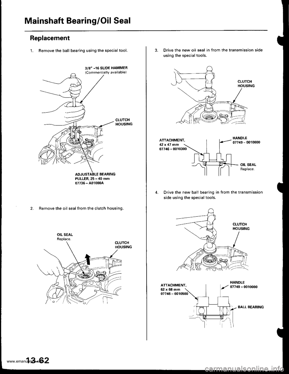
Mainshaft Bearing/Oil Seal
Replacement
1. Remove the ball bearing using the specialtool.
3/8" -16 SLIDE HAMMER(Commercially available)
PULLER.25 - ,10 mm07736 - A01000A
2. Remove the oil seal from the clutch housing.
13-62
BALL BEARING
3. Drive the new oil seal in from the transmission side
using the special tools.
ATTACHMENT,12x 17 .nfi07746 - 0010300
Drive the new bali bearing in from the transmission
side using the special tools.
ATTACHMENT.62x68mm07746 - 0010500
www.emanualpro.com
Page 502 of 1395
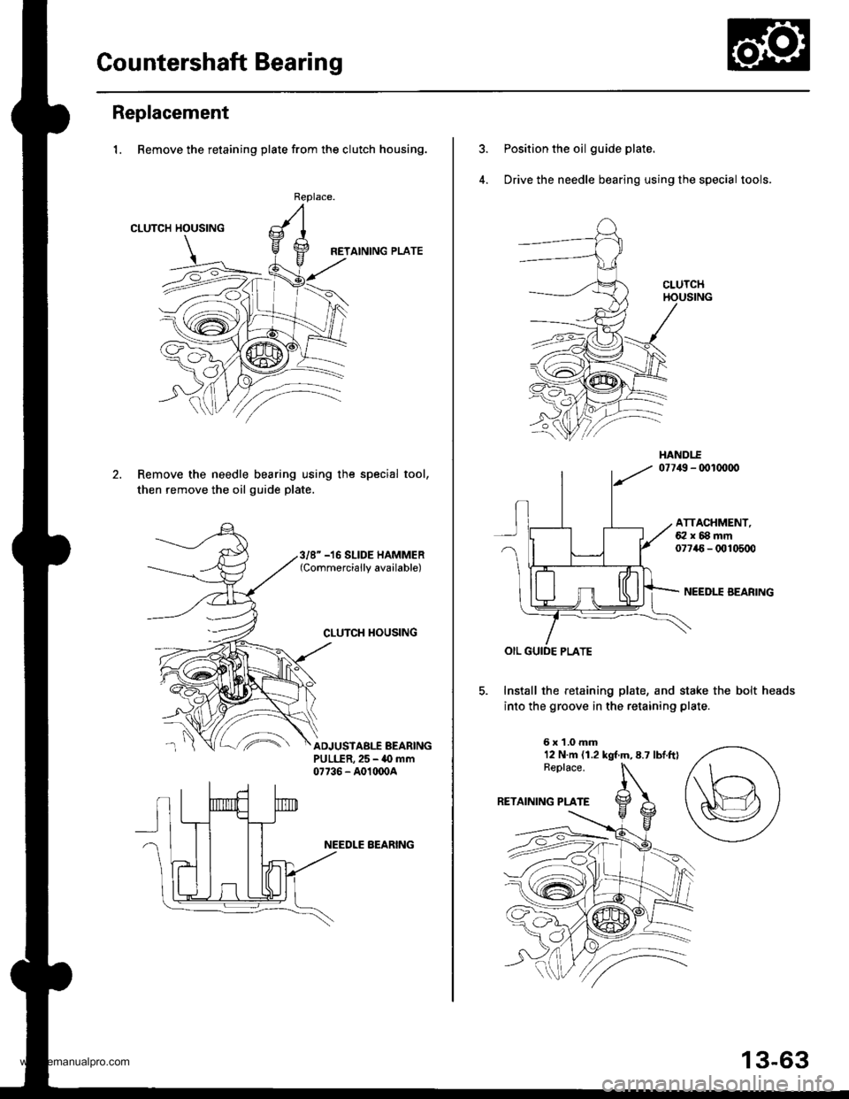
Gountershaft Bearing
Replacement
1. Remove the retaining plate from the clutch housing.
CLUTCH HOUSING
HETAINING PLATE
Remove the needle bearing using the special tool,
then remove the oil guide plate.
Replace.
3/8" -16 SLIDE HAMMER(Commercially available)
CLUTCH TIOUSING
^'ADJUSTABI.f BEARINGPULLER,25 - 40 mm07736 - A01(x)04
NEEDLE BEARING
Position the oil guide plate.
Drive the needle bearing using the special tools.
ATTACHMENT,62x88mm07746- 0t!105q)
NEEDII AEARING
Install the retaining plate, and stake the bolt heads
into the groove in the retaining plate
6x1.0mm12 N.m (1.2 kgt m,8.7 lbtftl
13-63
www.emanualpro.com
Page 503 of 1395
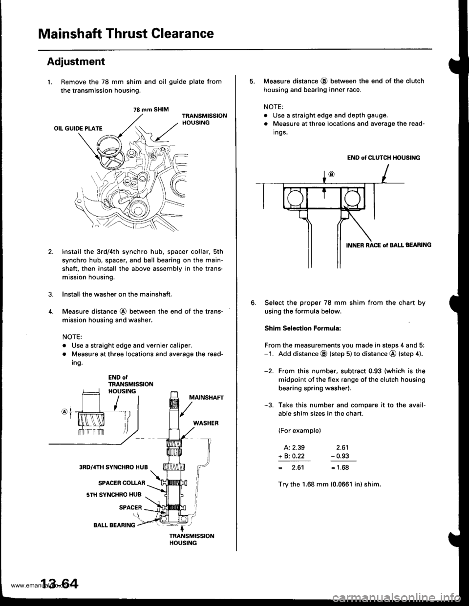
Mainshaft Thrust Clearance
Adjustment
l. Remove the 78 mm shim
the transmission housing.
4.
and oil guide plate from
Install the 3rd/4th synchro hub, spacer collar, sth
synchro hub, spacer, and ball bearing on the main-
shaft. then install the above assembly in the trans-
mission housing.
lnstallthe washer on the mainshaft.
Measure distance @ between the end of the trans-
mission housing and washer,
NOTE:
. Use a straight edge and vernier caliper.
. Measure at three locations and average the read-
Ing.
END otTRANSMISSION
MAINSHAFT
WASHER
3RD/4TH SYNCHRO HUB
SPACER COLLAR
sTH SYNCHRO HUB
SPACER
78 mm SHIM
13-64
BALL BEARING
5, Measure distance @ between the end of the clutch
housing and bearing inner race.
NOTE:
. Use a straight edge and depth gauge.
. Measure at three locations and avorage the read-
Ings.
END ot CLUTCH HOUSING
BEARING
Select the proper 78 mm shim from the chan by
using the formula below.
Shim S€lection Formula:
From the measurements you made in steps 4 and 5:-1. Add distance @ (step 5) to distance @ (step 4).
-2. From this number. subtract 0.93 (which is the
midpoint of the flex range of the clutch housing
bearing spring washer).
-3. Take this number and compare it to the avail-
able shim sizes in the chart.
(For example)
A: 2.39 2.61
+ Bi O.22 - 0.93
= 2.61= 1.68
Try the 1.68 mm (0.0661 in) shim.
www.emanualpro.com
Page 508 of 1395
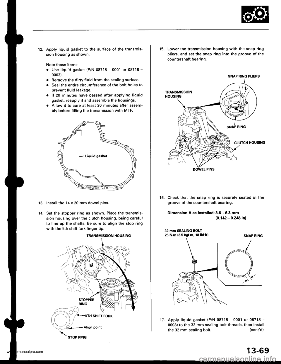
12. Apply liquid gasket to the surface of the transmis-
sion housing as shown.
Note these items:
. Use liquid gasket (P/N 08718 - 0001 or 08718 -
0003).
. Remove the dirty fluid from the sealing surface.
. Seal the entire circumterence of the bolt holes to
prevent fluid leakage.
. lf 20 minutes have passed after applying liquid
gasket, reapply it and assemble the housings.
a Allow it to cure at least 20 minutes after assem-
bly betore filling the transmission with MTF.
Install the 14 x 20 mm dowel pins.
Set the stopper ring as shown. Place the transmis-
sion housing over the clutch housing, being careful
to line up the shafts. Be sure to align the stop ring
with the 5th shift fork finger tip.
r3.
14.
TRANSMISSION HOUSING
SHIFT FORK
vk..*,
Align point
17.
the 32 mm sealing bolt.
15. Lower the transmission housing with the snap ring
pliers. and set the snap ring into the groove of the
countershaft bearing.
Check that the snap ring is securely seated in the
groove of the countershaft bearing.
Dimension A as installod: 3.6 - 6.3 mm
(0.142 - 0.2/8 in)
16.
32 mm SEALING BOLT25 N m 12.5 kgf.m, 18 lbf.ftlSNAP RING
(cont'd)
13-69
Apply liquid gasket (P/N 08718 - 0001 or 08718 -
0003) to the 32 mm sealing bolt threads, then install
SNAP RING PLIERS
DOWEL PINS
www.emanualpro.com
Page 675 of 1395
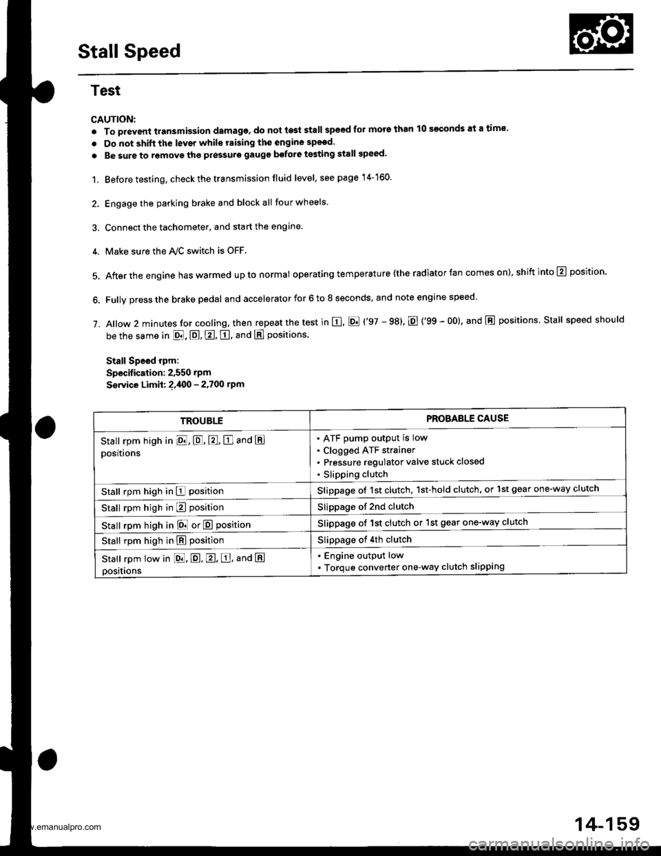
Stall Speed
Test
CAUTION:
. To prevent transmission damage, do not te3t stall speed for mors than 10 s€€onds at a time'
. Do not shift the lever while raising th€ engine spsed.
. Be sure to remove tho pressuro gauge bofore testing stall speed,
1. Before testing, check the transmission fluid level, s€e page 14-160.
2. Engage the parking brake and block all four wheels
3. Connect the tachometer, and start the engane.
4. Make sure the Ay'C switch is OFF
5. After the engine haswarmed upto normal operating temperature (the radiator fan comes on),shiftinto@ position.
6. Fully press the brake pedal and accelerator for 6 to 8 seconds, and note engine speed '
j. A|ow 2 minutes for cooling, then repeat the test in E, E ('97 - 98). E {'99 - 00}, and E positions. Stall speed should
be the same in E, E, E, tr. and E positions
Stall Speed rpm:
Specitication: 2,550 rpm
S€rvice Limit: ?,400 - 2.700 rpm
TROUBLEPROBAELE CAUSE
Stall rpm high in El, E, E, E and E
positions
ATF pump output is low
Clogged ATF strainer
Pressure regulator valve stuck closed
Slipping clutch
Stall rpm high in E positionSlippage of 1st clutch, 1st-hold clutch, or 1st gear one-way clutch
Stall rpm high in E positionSlippage of 2nd clutch
stall rpm high in E! or E positionSlippage of 1st clutch or 1st gear one-way clutch
Stall rpm high in E positionSlippage of 4th clutch
Stall rpm low in [dd, E. E, E, ana E
positions
. Engine output low
. Torque converter one-way clutch slipping
14-159
www.emanualpro.com
Page 677 of 1395

Pressure Testing
Changing
NOTE: Keep all foreign particles out of the transmis-
sion.
1. Bring the transmission up to operating temperature
(the radiator fan comes on) by driving the vehicle.
Park the vehicle on level ground. turn the engane
off. then remove the drain Plug.
NOTE: lf a cooler flusher is to be used, see page
14-264 and 14-265.
TRANSMISSIONEND COVER
DRAIN18 x 1.5 mmSEALING WASHEBReplace.49 N.m {5.0 kgt.m, 36 lbf.tl)
Reinstall the drain plug with a new sealing washer,
then refill the transmission with the recommended
fluid to the uDper mark on the dipstick. Always use
Genuine Honda Premium Formula Automatic
Transmission Fluid (ATF) Using a non-Honda ATF
can affect shift quality.
Automatic Transmission Fluid Capacity:
4WD;
2.9 { (3.1 US qt. 2.6 lmp qt) 8t change
5.8 ? {7.2 US $, 6.0 lmp qt} at ovethaul
2WD:
2.7 | l2.S US qt,2.1lmp qtl ai change
5.9 ? {6.2 US $, 5.2 lmp qtl at ovolhaul
2.
a
a
1.
Wlrile testing, be careful of the rotaling wheols.
Mako sure lifts, iacks, and safety stands ar€ placed
properly (see scction 11.
Before testing, be sure the transmission fluid is
filled to the proPer level.
4WD:
Raise the vehicle (see section 11.
2WD:
Raise the front of the vehicle, and make sure it is
securely supported. Set the parking brake, and block
both rear wheels securely.
Allow all four wheels {4WD) or front wheels (2wD}
to rotate freely.
Warm up the engine (the radiator fan comes on),
then stop it and connect the tachometer.
Connect the oil pressure gauges to each inspection
hole securely, and do not allow dust or other foreign
particles to enter the inspection holes.
TOROUE: 18 N'm ll.8 kgf'm, 13 lbf'ft)
5.
A/T PRESSURE HOS€,2210 mm07MAJ - PYiOllA
{4 Requircd}
,4'/"' ,a
W'
A/T PRESSURE HOSEADAPTER07MAJ - PYt0120(il Rcquiledl
6. Measure the following Pressure:. Line Pressure ..........,14-162
. 1st. 1st-hold Clutch Pressure .............'. 14-162
. 2nd,3rd and 4th Clutch Pressure .......... 14-163
7. Install new sealing washers and the sealing bolts in
the inspection holes, and tighten to the specified
toroue.
(cont'd)
A/T OIL PRESSUREGAUGE SET W/PANEL07{06 - 0020400
/4\\-J-- (
+..\.-.\-'-\
A/T LOW PBESSUREGAUGE w/PANEL07406 - 0070300
TOROUE: 18 N'm 11.8 kgf'm, 13 lbf'ft)
14-161
www.emanualpro.com
Page 703 of 1395
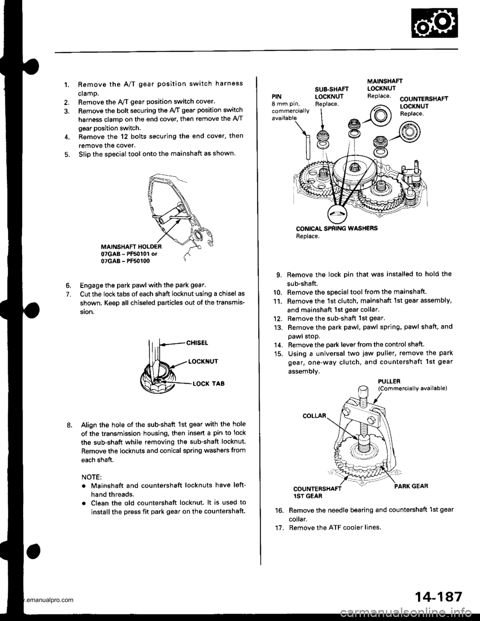
1. Remove the A/T gear position switch harness
cramp.
Remove the y'VT gear position switch cover.
Remove the bolt securing the ly'T gear position switch
harness clamp on the end cover, then remove the A/T
gear position switch.
Remove the 12 bolts securing the end cover. then
remove the cover.
Slip the special tool onto the mainshaft as shown.
6. Engage the park pawl with the park gear.
7. Cut the locktabs of each shaft locknut using a chisel as
shown. Keep all chiseled particles out of the transmis-
ston.
M=tt"
Align the hole of the sub-shaft 1st gear with the hole
of the transmission housing. then insert a pin to lock
the sub-shaft while removing the sub-shaft locknut.
Remove the locknuts and conical spring washers from
each shaft.
NOTE:
Mainshaft and countershaft locknuts have left-
hand threads.
Clean the old countershaft locknut. lt is used to
install the press fit park gear on the countershaft.
MAINSHAFT
PIN8 mm pin,
commercially
SUB-SHAFTLOCKNUTReplace.COUNTERSHAFTLOCKNUTReplace.
CONICAL SPNING WASHERSReplace.
9. Remove the lock pin that was installed to hold the
sub-shaft.
10. Remove the special tool from the mainshaft.
11. Remove the 1st clutch, mainshaft 1st gear assembly,
and mainshaft 1st gear collar.'12. Remove the sub-shaft 1st gear.
13. Remove the park pawl, pawl spring, pawl shaft. and
pawl stoP.
14. Remove the park lever from the control shaft.
15. Using a universal two jaw puller, remove the park
gear, one-way clutch, and countershaft 1st geal
assemblv.
{Commercially available)
1SY GEAR
Remove the needle bearing and countershaft 1st gear
co ar.
Remove the ATF cooler lines,
LOCKNUTReplace.
2\
Irot)
PULLER
11.
14-187
www.emanualpro.com
Page 719 of 1395
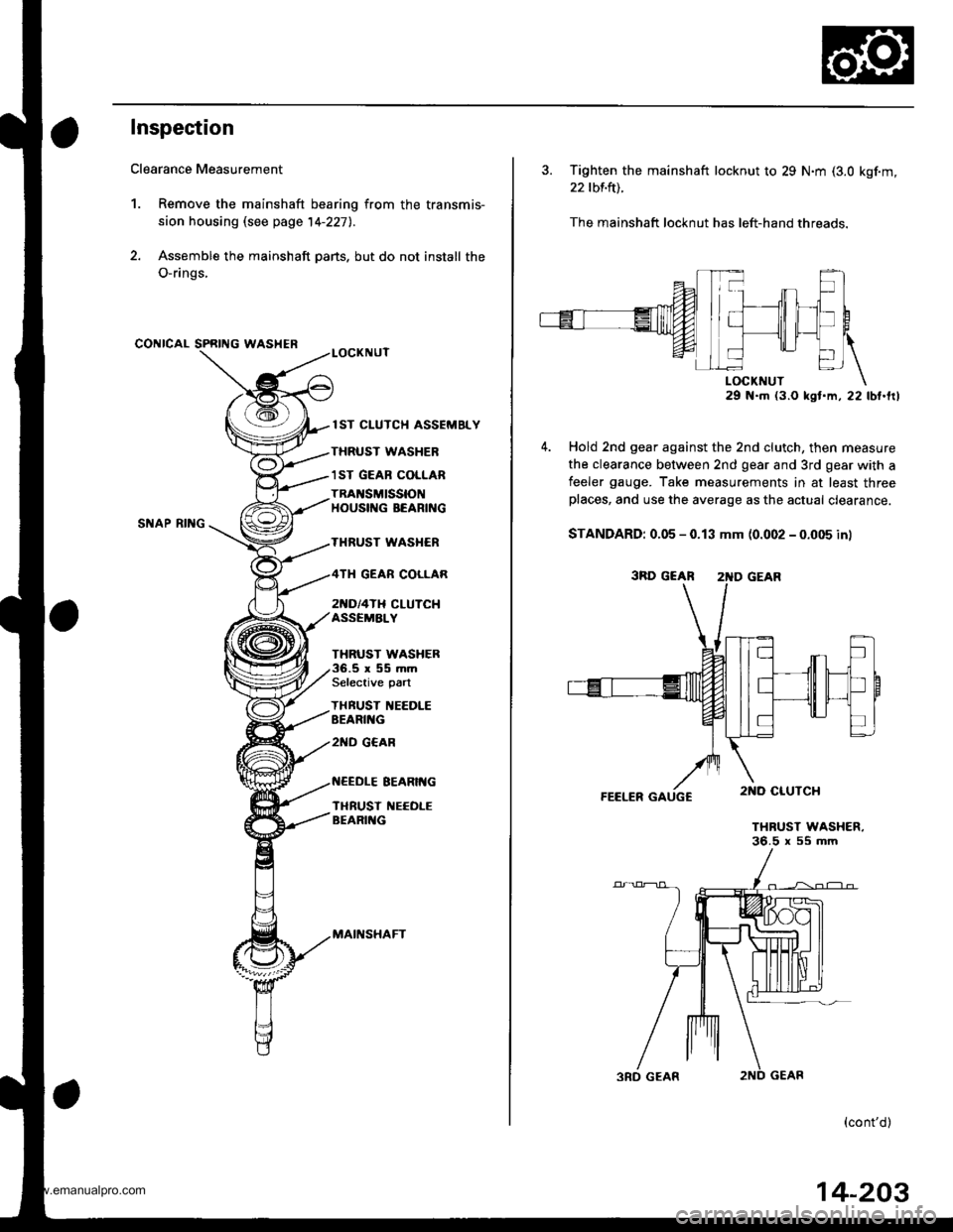
Inspection
Clearance Measurement
1. Remove the mainshaft bearing from the transmis-
sion housing lsee page 14-227l..
2. Assemble the mainshaft parts, but do not install the
O-rings,
CONICAL SPRING WASHER
SNAP RII{G
lST CLUTCH ASSEMELY
THRUST WASHER
1ST GEAB COLLAR
TRAI{SMISSIONHOUSIf{G BEARING
THRUST WASI{ER
2[{D/4TH CLUTCHASSEMALY
GEAR COLLAR
THRUST WASHER.5r55mmSelective part
THBUST IIEEDLEEEARII{G
2ND G€AR
EEARIt{G
TI{RUST NEEOLEBEARII{G
MAII{SHAFT
3. Tighten the mainshaft locknut to 29 N.m (3.0 kgf.m,
22 tbf.ft).
The mainshaft locknut has left-hand threads.
29 N.m (3.O kst.m, 22 lbt.frl
Hold 2nd gear against the 2nd clutch, then measure
the clearance between 2nd gear and 3rd gear with a
feeler gauge. Take measurements in at least threeplaces, and use the average as the actual clearance.
STANDARD: 0.05 - 0.13 mm (0.002 - 0.005 in)
FEELER GAUGC
THRUST WASHER.36.5 x 55 mm
(cont'd)
3RD GEAR 2'{D GEAR
14-203
www.emanualpro.com
Page 722 of 1395
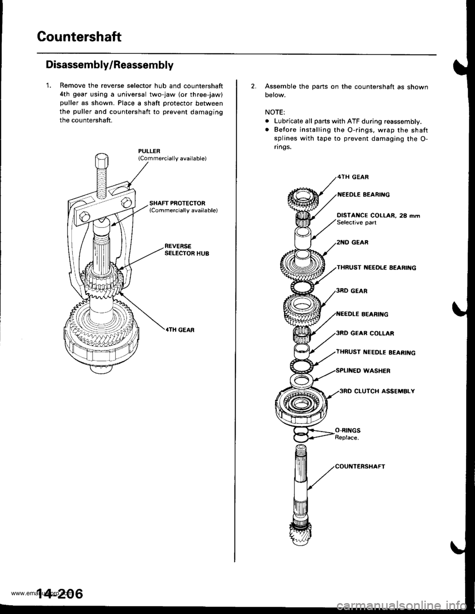
Gountershaft
Disassembly/Reassembly
1. Remove the reverse selector hub and countershaft
4th gear using a universal two-jaw lor three-jaw)
puller as shown. Place a shaft protector between
the puller and countershaft to prevent damaging
the countershaft.
{Commercially available)
REVERSESELECTOR HUB
.TH GEAR
14-206
2. Assemble the parts on the countershaft as shown
below.
NOTE;
. Lubricate all parts with ATF during reassembly.
. Before installing the O-rings. wrap the shaft
splines with tape to prevent damaging the O-
rings.
4TH GEAR
BEARI'{G
DISTANCE COLLAR, 28 mmSelective oart
GEAR
THRUST ]{EEOL€ AEARIIIG
GEAR COLLAR
THRUST I{EEDLE EEARII{G
WASHER
3RO CLUTCH ASSEMBLY
SEARII{G
O-RINGSReplace.
www.emanualpro.com
Page 723 of 1395
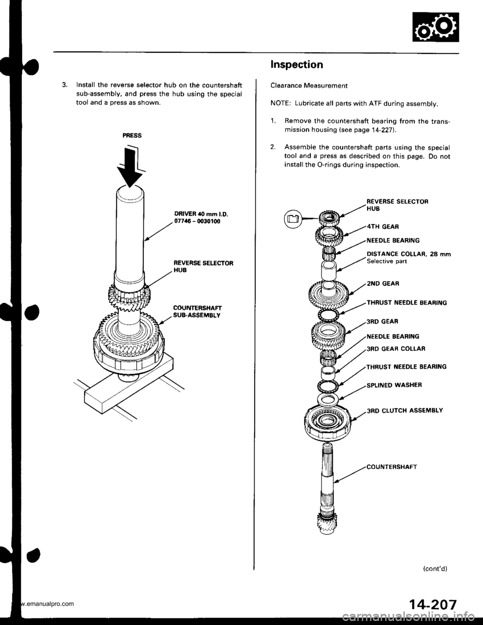
3. Install the reverse selector hub on the countershaft
sub-assembly, and press the hub using the special
tool and a press as shown.
DRIVER to mm l.D.07746 - 0030100
REVERSE SEI.ICTORHUB
COUNTERSHAFTSU&ASSEMBLY
Inspection
Clearance Measurement
NOTE: Lubricate all parts with ATF during assembly.
1. Remove the countershaft bearing from the trans-
mission housing lsee page 14-227).
2. Assemble the countershaft parts using the special
tool and a press as described on this page. Do not
install the O-rings during inspection.
R€VERS€ SELECTORHUB
GEAR
NEEDLE BEARING
DISTANCE COLLAR, 28 mmSelective part
2NO GEAR
THRUST NEEDLE BEARING
GEAR
NEEOLE BEARING
GEAR COLIAR
THRUST NEEDLE BEARING
WASHER
CLUTCH ASSEMBLY
(cont'd)
14-207
www.emanualpro.com