seat memory HONDA CR-V 1999 RD1-RD3 / 1.G Owner's Manual
[x] Cancel search | Manufacturer: HONDA, Model Year: 1999, Model line: CR-V, Model: HONDA CR-V 1999 RD1-RD3 / 1.GPages: 1395, PDF Size: 35.62 MB
Page 1375 of 1395

Troubleshooting
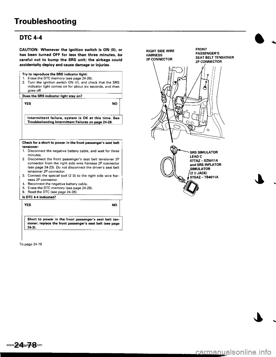
DTC 4-4
CAUTION: Whenever the ignition switch is ON (ll), or
has been turned OFF tor less than thlee minutes. be
careful nol to bump the SRS unit; the airbags could
accidontally deploy and cause damage or iniuries.
RIGHT SIDE WIREHARNESS2P
FRONTPASSENGER'S
SRS SIMULATORLEAD C07TAZ - SZ5011Aand SRS INFLATOR
,StMULATOR/(2 o JACK)
t _07SAZ - TBiro1 1A
Try to reproduce the SRS indicator light:1. Erase the DTC memory {see page 24-28).2. Turn the ignition switch ON (ll), and check that the SRSindicator light comes on for about six seconds, and thengoes off.
Doos the SRS indicator light 3t.y on?
vEsNO
Intermittent f!ilure, system is OK at this time. SeeT.oubleshooting Intermittent F.ilures on page 24-28.
Check tor a 3horl lo power in the frolt pass€nge.'s s€at belttensaoneri'1. Disconnect the negative battery cable, and wait for threemrnutes.2. Disconnect the front passenger's seat belt tensioner 2Pconnector from the right side wire harness 2P connector{see page 24-23}. Do not disconnect the driver's seat belttensioner 2P connector.3. Connect the special tool (2 O) to the right side wire har-ness 2P connector.4. Reconnect the negaiive baftery cable.5. Erase the DTC memory (see page 24-28).6. Read the DTC lsee page24-261.
ls DTC 4-,1 indicated?
YESNO
Short to power in the front passong6r'3 seat belt ten-sioner; replace the front passongar'3 s€at beh {see page21-31.
To page 24'79
24-78.
www.emanualpro.com
Page 1376 of 1395

)
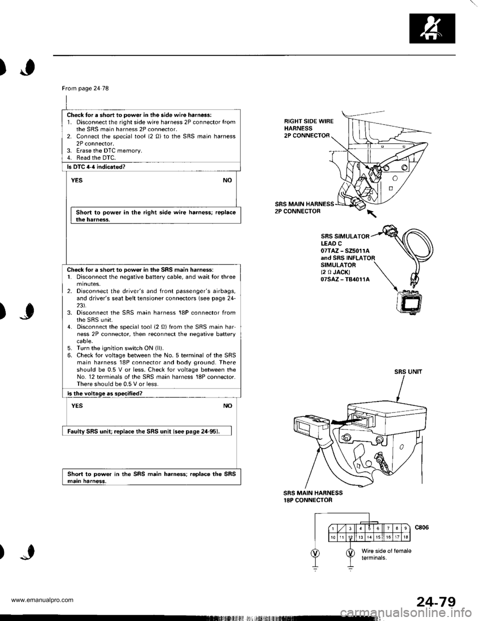
RIGHT SIDE WIREHARNESS2P CONNECTOR
SRS MAIN2P CONNECTOR
SBS SIMULATORLEAD C07TAZ - SZ5011Aand SRS INFLATORSIMULATOR \(2 0 JACK) \07sAz-T84011A \\
)J
)
@
SRS MAIN HARNESS18P CONNECTOR
Ftom page 24 78
Check for a short to power in the side wire harn6s:1. Disconnect the right side wire harness 2P connector fromthe SRS main harness 2P connector,2- Connect the special tool (2 0) to the SRS main harness2P connector.3. Erase the DTC memory.4. Read the DTC.
ls DTC 4-{ indicated?
YESNO
Short to power in the right side wire harness; replacethe harness.
Check tor a short to oow6r in the SRS main harness:1. Disconnect the negative battery cable, and wait for threemtnutes,2. Disconnect the driver's and front passenger's airbags,and driver's seat belt tensioner connectors (see page 24-23).3. Disconnect the SRS main harness 18P connector fromthe sRS unit.4. Disconnect the special tool i2 0) from the SRS main harness 2P connector, then reconnect the negative batterycaore.5. Turn the ignition switch ON (ll).
6. Check for voltage between the No. 5 terminal of the SRSmain harness 18P connector and body ground. Thereshould be 0.5 V or less. Check for voltage between theNo. 12 terminals of the SRS main harness 18P connector.There should be 0.5 V or less.
ls the voltage as specified?
NOYES
Faulty SRS unit; replace the SRS unit (see pase 24-95).
Short to power in the SRS main harness; replace the SRSmain harness.
24-79
www.emanualpro.com
Page 1377 of 1395

Troubleshooting
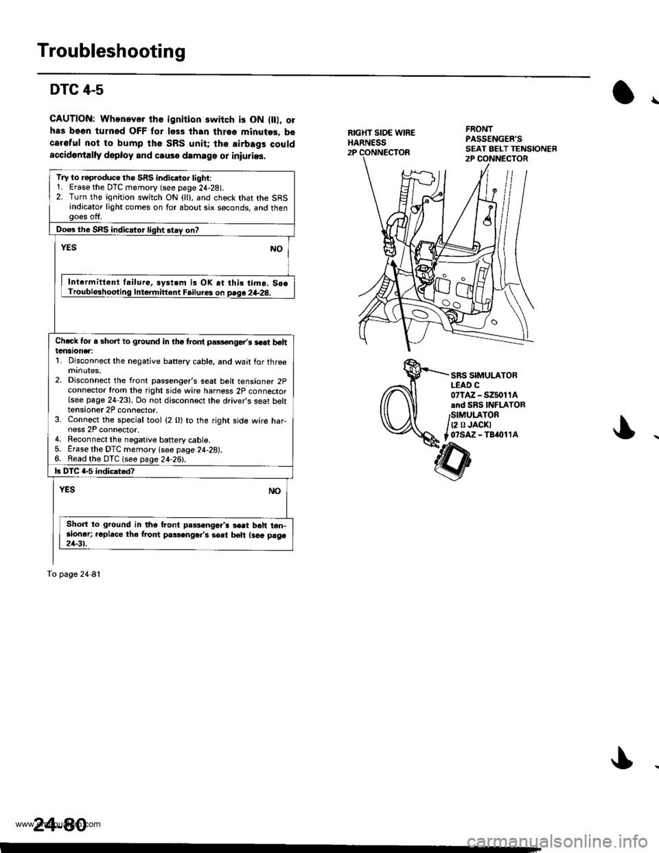
DTC 4-5
GAUTION: Whonever the ignition switch is ON fll). olhas be6n turned OFF for less than thrso minuter. becareful not to bump the SRS unit; the airbags couldaccidontally deploy and causo damage or iniurias.
\
RIGXT SIOE WIREHARNESS2P
FRONTPASSENG€R'S
SRS SIMULATORLEAD C07lAz - s2501 1Aand SRS INFLATORSIMULATOR
t2 0 JACKTo?saz - Taaol 1A
Try to roproduco th. SRS indicrtor tighi:1. Erase the DTC memory (see page 24-28).2. Turn the ignition switch ON (ll), and check that the SRSindicator light comes on for about six seconds, and thengoes off.
Doe3 the SRS indicator light stay on?
YESNO
Int€rmittent t.ilurG, syst.m is OK at thi! timo. So€Troubleshooting Inte.mift€nt Failure3 on psqa 2+28.
Chcck Ior a shon to ground in the trodt pars€nge/s lert behtensionea:1. Disconnect the negative battery cable, and wait for threemrnutes.2. Disconnect the front passenger's seat belt tensioner 2pconnector trom the right side wire harness 2p connector(see page 24-23). Do not disconnect the driver's seat bektensioner 2P connector.3. Connect the special tool (2 0) to the right side wire har-ness 2P connector,4. Reconnect the negative battery cable.5. Erase the DTC memory lsee page 24-28).6. Read the DTC (seo page 24-26!-.
k DIC G5 indicated?
NOYES
Short to ground in the Lont passengc.'3 3€rt boh ton-sioner; replace tho from p.rlenger's sort beh ls€a page21-3t.
To page 24-81
24-80
www.emanualpro.com