oil pressure HONDA CR-V 1999 RD1-RD3 / 1.G Workshop Manual
[x] Cancel search | Manufacturer: HONDA, Model Year: 1999, Model line: CR-V, Model: HONDA CR-V 1999 RD1-RD3 / 1.GPages: 1395, PDF Size: 35.62 MB
Page 29 of 1395
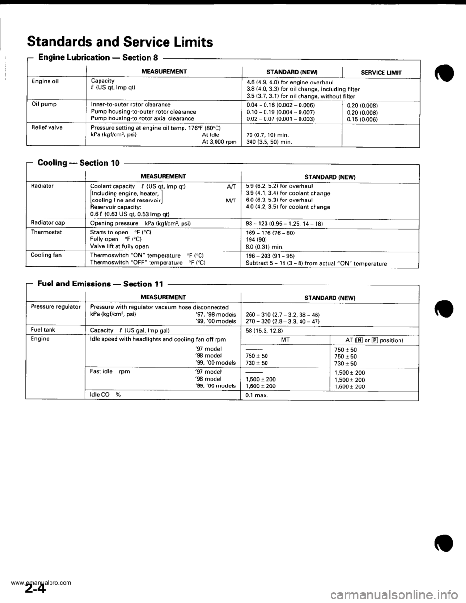
Standards andService Limits
Engine LubricationSection 8
CoolingSection 10
Fuel and EmissionsSection 11
MEASUREMENTSTANDARO {NEWISERVICE LIMIT
Engine oilCapacityf (US qt, lmp qt)4.6 (4.9, 4.0)Ior engine overhaul3.8 {4.0,3.3)for oilchange, including filter3.5 (3.7, 3.1) for oil change, without Iilter
OilpumpInner-to-outer rotor clearancePump housing-to-outer rotor clearancePump housing-to rotor axial clearance
0.04 - 0.16 (0.002 - 0.006)0.10 -0.19 (0.004 - 0.007)0.02 -0.07 (0.001 - 0.003i
0.20 (0.008)
0.20 (0.008)
0.15 (0.006)
Relief valvePressure setting at engine oil temp. 176'F (80'C)kPa (kgt/cm,, psi) At ldleAt 3,000 rpm70 (0.7, 10) min.340 {3.5,50) min.
MEASUREMENTSTANDARO INEW}
RadiatorCoolant capacity , (US q1, lmp qt)
llncluding engine, heater, ILcooling line and reservoirlReservoir capacity:0.61 (0.63 US qt,0.53lmp qt)
M/T
5.9 {6.2, 5.2}tor overhaul3.9 (4.1, 3.4ifor coolant change6.0 (6.3, 5.3ifor overhaul4.0 (4.2, 3.5) for coolant change
Radiator capOpening pressure kPa (kgf/cm?, psi)93 - 123 (0.95 - 1.25, 14 18)
ThermostatStarts to open 'F 1"C)Fully open 'F ("C)
Valve lift at tully open
169 - 176 (76 - 80)194 (90)
8.0 (0.31imin.
Cooling fanThermoswitch "ON" temperature "F {'C)Thermoswitch "OFF" temperature 'F ('C)196 - 203 (91 - 95)Subtract 5 - 14 (3 - 8) trom actual "ON" temperature
MEASUREMENTSTANDARD INEW}
Pressure regulatorPressure with regulator vacuum hose disconnectedkPa (kgflcm'�, psi) '97,'98 models'99, '00 rnodels260 - 31012.7 3.2,38- 46)270 -32012.8 3.3,40 - 471
FueltankCapacity / (US gal, lmp gal)58 (15.3, 12.8)
E ngineldle speed with headlights and cooling fan off rpm'97 model'98 model'99, '00 models
MTAT {E or E position)
750 r 50730 1 50
750 t 50750 r 507301 50
Fast idle rpm '97 model'98 model'99, '00 models1,5001 2001,600 r 200
1,5001 2001,5001 2001,600 r 200
ldle CO %0.1 max.
2-4
www.emanualpro.com
Page 30 of 1395
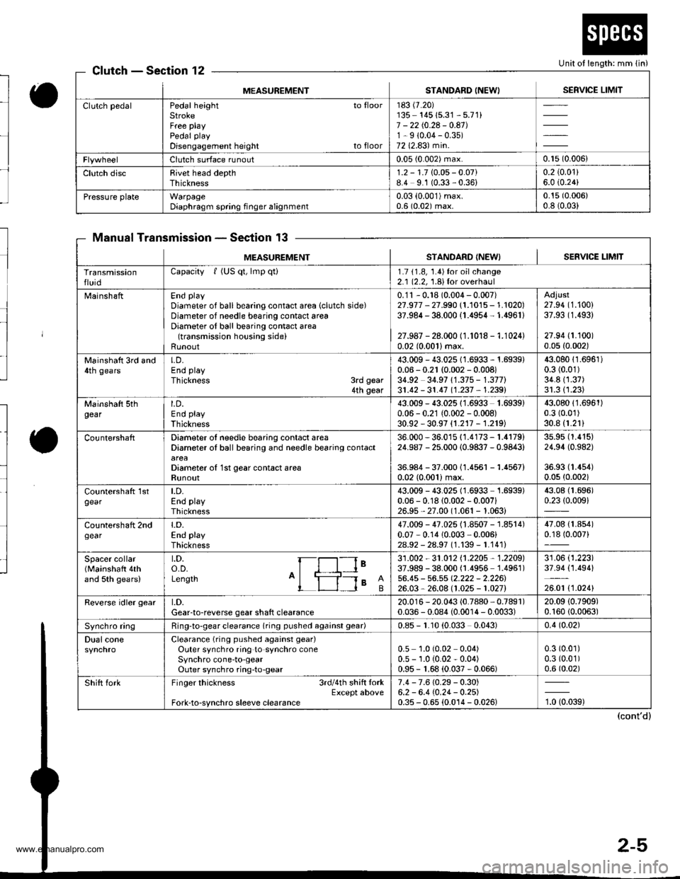
Unit of length: mm lin)ClutchSection 12
Manual TransmissionSection 13
MEASUREMENTSTANDARD INEWISERVICE LIMIT
Clutch pedalPedal height to floorStrokeFree playPedal play
Disengagement height to floor
183 (7.20)
135- 14515.31 - 5.71)7 - 2210.24 - 0.41J1-9 (0.04-0.35)
7212.83) min.
Clutch surface runout0.05 (0.002) max.0.r5 (0.006)
Clutch discRivet head depthThickness1.2 - 1.710.05- 0.07)8.4 9.1 (0.33,0.36)0.2 (0.01)
6.0 i0.24)
Pressure plateWarpageDiaphragm spring finger alignment0.03 (0.001)max.
0.6 (0.02) max.0.15 (0.006)
0.8 (0.03)
MEASUREM€NTSTANDARD INEW} I SERVICE I-IMIT
TransmissionfluidCapacity f (US qt, lmp qti1.7 11.8, 1.4)for oilchange2.1 (2.2, 1.8){or overhaul
MainshaftEnd play
Diameter of ball bearing contact area (clutch side)Diameter of needle bearing contact areaDiameter of ball bearing contact area(transmission housing side)Runout
0.'11 - 0.18 (0.004 - 0.007)27.977 - 27.990 (1.1015 - 1.1020)37.984 - 38.000 (1.4954- 1.4961)
27.987 - 28.000 (1.1018 - 1.1024)0.02 (0.0011max.
Adjust27.94 (1.100)
37.93 (1.493)
27.94 (1.100)
0.05 {0.002)
Mainshatt 3rd and4th gearsLD.End play
Thickness 3rd gear4th gear
43.009 - 43.025 1 1.6933 - 1.6939)0.06 - 0.21 (0.002 - 0.008)34.92 34.97 11.375 - 1.377)31.42 - 31.4'7 11.237 , 1.2391
43.08011.6961)0.3 (0.01)
34.811.37)31.311.23)
Mainshaft sthgearLD.End play
Thickness
43.009 - 43.02511.6933 1.6939)0.06 - 0.21 (0.002 - 0.008)30.92 - 30.97 {1.217 - 1.219)
43.08011.6961)0.3 (0.01)
30.8 (1.21)
CountershaftDiameter ol needle bearing contact areaDiameter oI ball bearing and needle bearing contact
Diameter o{ 1st gear contact areaRunout
36.000 - 36.015 {1.4173 - 1.4179)24.987 - 25.000 (0.9837 - 0.9843)
36.984 - 37.00011.4561 -1.4567)
0.02 (0.001)max.
3s.95 (1.415)
24.94 (0.982)
36.93 (1.4s4)
0.0s (0.002)
countershatt 1stgearLD.End playThickness
43.009 - 43.025 (1.6933 1.6939)0.06 - 0.18 (0.002 - 0.007i26.9s,27.00 (1.061 - 1.063)
43.08 (1.696)
0.2310.009)
Countershaft 2ndgeart.D.End playThickness
47.009 - 47.025 (1.8507 - 1.8514)0.07 - 0.14 10.003 ,0.006)
2As2 - 2a.97 l�1.139-1.1411
47.08 {1.854)0.18 (0.007)
Spacer collar(Mainshaft 4thand 5th gears)
t.D.o.D.Length A'ls I
le31 .002 - 31 .O12 11 .2205 , 1 .2205)37.989 - 38.000 (1.4956 1.4961)56.45 - 56.55 Q.222 - 2.226126.03,26.08 (1.025 - 1.027)
31.06 (1.223)
37.94 (1.494)
26.01 t1 .0241
Reverse idler geart.D.Gear-to-reverse gear shaft clearance20.01 6 - 20.043 (0.7880, 0.7891)0.036 - 0.084 (0.0014 - 0.0033)20.09 (0.7909)
0.16010.0063)
Synchro ringRing-to-gear clearance (ring pushed againsl gear)0.85 - r.10 (0.033 0.043)0.4 (0.02)
Dual coneClearance (ring pushed against gear)
Outer synchro ring to synchro coneSynchro cone-to-gearOuter synchro ring-to-gear
0.5 1.0 (0.02 0.04)0.5 - 1.0 (0.02 - 0.04)0.95 - 1.68 (0.037 - 0.066)
0.3 (0.01)
0.3 (0.01)
0.6 (0.02)
Shift forkFinger thickness 3rdl4th shift lorkExcept aboveFork-to-synchro sleeve clearance
7.4 - 7.6 (0.29 - 0.30)6.2 - 6.4 (0.24- 0.2s)0.35 - 0.65 (0.0't4 - 0.026)'t, torag)
www.emanualpro.com
Page 35 of 1395
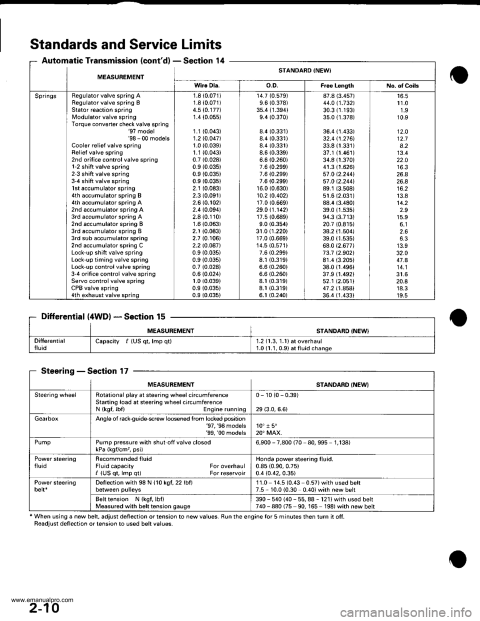
Standards and Service Limits
Automatic Transmission (cont'dl - Section 14
Differential (4WDl * Section 15
MEASUREMENTSTANOABD {NEW'
SteeringSection 17
* When using a new belt, adjust deflection or tension to new values. Run the engine for 5 minutes then turn it off.Readjust dellection or tension to used belt values.
MEASUREMENTSTANDARO INEWI
Wire Dia.o.D.Fiee LengthNo. of Coils
SpringsRegulator valve spring ARegulator valve spring BStator reaction springModulator valve springTorque convener check valve spring'97 model'98 - 00 modelsCooler relief valve springRelief valve spring2nd orilice control valve spring1-2 shitt valve spring2 3 shift valve spring3-4 shift valve spring1st accumulator spring4th accumulator spring B4th accumulator spring A2nd accumulator spring A3rd accumulator spring A2nd accumulator spring B3rd accumulator spring I3rd sub accumulator spring2nd accumulator spring CLock-up shift valve springLock-up timing valve springLock'up control valve spring3'4 orifice control valve springServo control valve springCPB valve spring4th exhaust valve spring
1.8 10.071)1.8 i0.071)4.5 (0.177)
1.4 {0.055)
1.1 (0.043)
1.2 (0.047)
1.0 (0.039)
1.1 (0.043)
0.7 (0.028)
0.9 (0.035)
0.9 (0.035)
0.9 (0.03s1
2.1 (0.083)
2.3 (0.091)
2.6 (0.102)
2.410.094)2.8 (0.110)
1.6 (0.063)
2.1 (0.083)
2.7 {0. r06)2.2lO.OA7)0.9 (0.035)
0.9 (0.035)
0.7 (0.028)
0.6 (0.024)
1.0 (0.039)
0.9 (0.035)
0.9 (0.035)
14.7 (0.579)
9.6 (0.378)
35.4 {1.394}9.4 (0.370)
8.4 (0.331)
8.4 (0.331)
8.4 (0.331)
8.6 (0.3391
6.6 (0.260i
7.6 {0.299}7.6 {0.299)7.6 {0.299)16.0 (0.630)
10.2 to.402l17.0 (0.669)
29.0 \1.1421'r7.510.689)
9.0 (0.354)
31.0 (1.220)17.0 (0.669)
14.510.571)7.610.299i8.1 {0.319}6.6 (0.260)
6.6 (0.260i
8.1 (0.319)
8.1 {0.319)6. t (0.240)
87.8 (3.457)
44.011.132130.31r.193)35.0 {1.378)
36.4 {1.433)32.4 tl.216J33.8 {r.331)37.1 (1.461)
34.8 (1.370)
41.3 (1.626)
57 .0 (2.2441
57 .0 12.244189.1 (3.508)
51.6 (2.031)
88.4 (3.480)
39.011.s35)94.313.713)20.7 10.8r5)38.2 (1.504)
39.0 (1.535)
68.0 (2.677)
73.7 12.902)8r.4 (3.205)
38.0 fl.496)37.9 (1.492)
52.1 (2.051)
41 .2 t .A5Al36.4 (1.4331
r 1.01.910.9
12.O12.78.213.422.0
26.426.8
13.814.22.915.9
2.66.3
32.047.A
20.8'18.3'19.5
Capacity f (US qt, lmp ql)1.2 (1.3, 1.1) at overhaul1.0 (1.1, 0.91 at fluid change
MEASUREMENTSTANDARD INEWI
Steering wheelRotational play at steering wheel circumferenceStaning load at steering wheelcircumferenceN {kgf, lbl) Engine running
0- 10 (0 - 0.39)
29 (3.0,6.6)
GearboxAngle of rack$uide-screw loosened lrom locked position'97, '98 models'99, '00 models10" 1 5"20" MAX.
PumpPump pressure with shut off valve closedkPa (kgvcm,, psi)6,900 - 7,800 (70 80,995 1,138)
Power steeringfluidRecommended tluidFluid capacity For overhaulI {US qt, lmp q0 For reservoir
Honda power steering fluid.0.85 (0.90,0.75)
0.4 {0.42,0.35)
Power steeringbelt*Deflection with 98 N {1O kgl,22lht)between pulleys11.0 14.5 (0.43 0.57)with used belt7.5 - 10.0 (0.30 0.40) with new belt
Belt tension N {kgt, lbf}Measured with belt tension gauge390 - 540 (40 - 55, 88 - 121) with used belt740-880 (75 90, 165 198)with new belt
2-10
www.emanualpro.com
Page 38 of 1395

--
-
METRICITEMENGLISHNOTES
AIR CONDITIONINGCooling capacity3,520 Kcal/h j 14,000 BTU/h
Compressor Type/manutacturerNo. of cylinderCaPacityMax. speedLubricant capacityLubricant type
Scroll/KElHlN
85.7 mf/rev | 5.23 cu'in/rev10,000 rpm130mf 1 algIlozsP-10
Condenser TypeCorrugated fin
Evaporator TypeCorrugated fin
Blower TypeMotor inputSpeed controlMax. capacity
Sirocco fan200 w 112 v4-Speeo440 m3/h 15,500 cu fvh
Temperature control
Compressor clutch TypePower consumptionDry, single plate, poly-V-belt drive40 W max./12 VAt 68'F (20 C)
Befrigerant TypeOuantity
HFC-134a 1R-134a)zoo o' g 24j an oz
STEERING SYSTEMTypeOverall ratioTurns, lock to lockSteering wheel diameter
Power assisted, rack and pinion
SUSPENSIONType Front
Bear
Shock absorber Front and Rear
Independent double wishbone, coil springwith stabilizerIndependent double wishbone, coil springwith stabilizerTelescopic, hydraulic nitrogen gas tilled
WHEEL ALIGNMENTCamber
CasterTotaltoe
FronthearFrontFrontRear0inln 1/16 in0mmln2mm
0'- r"00'2.10'�
BRAKE SYSTEMTvpe
Pad surface areaLining surface areaParking brake
Front
RearFrontRearTvpe
Power-assisted selt-ad,ustingventilated discPower assisted self-adiusting drum49 cm, x 2 7.6 sq-in x 273 cm, x2 11.3 sq-in x 2Mechanical actuating, rear two wheel brakes
Drum brake
TIRESize and pressureSee tire inlormation label.
ELECTRICALBafteryStarterAlternator
In under-dash fuse/relay boxIn under hood fuse/relay box
In underhood ABS fuse/relay boxHeadlightsFront turn signal lights
Front parking lightsFront side marker lightsRear side marker lightsRear turn signal lightsErake/parking lightsBack-up lightsCeiling lights {fronvrear)License plate lightSpotlightsHigh mount brake lightlgnition key lightAshtray lightGauge lightsIndicator lightslllLrmination and pilot IightsHeater illumination lights
12 V, 36 AH/s HR12V 1.0, 1.1 kW12V 100A
7.5 A, 10 A, 15 A, 20 A7.5 A, 10 A, 15 A, 20 A, 30 A, 40 A'100 A7.5 4,20 A. 40 A12V 60/55 W12 V- 21 W ('97 model),12 V - 27 W ('98-00 models)12V 5 W {'97 model),3 CP ('98 - 00 models)12V-8W12 V,3 CP12V-21W12 V 2115 W12V 21 CP (18 W)12V-8W12V-8W12V-5W12V -21W
12 V- 1.4 W12V 1.4 W12 V 1.4 W,3 W,3.4 W12V-0.84W, 1.12 W, 1.4 W,3 W, LED12 V - 0.84 W, 1.4 W, LED12 V,1.4 W
2-13
www.emanualpro.com
Page 119 of 1395
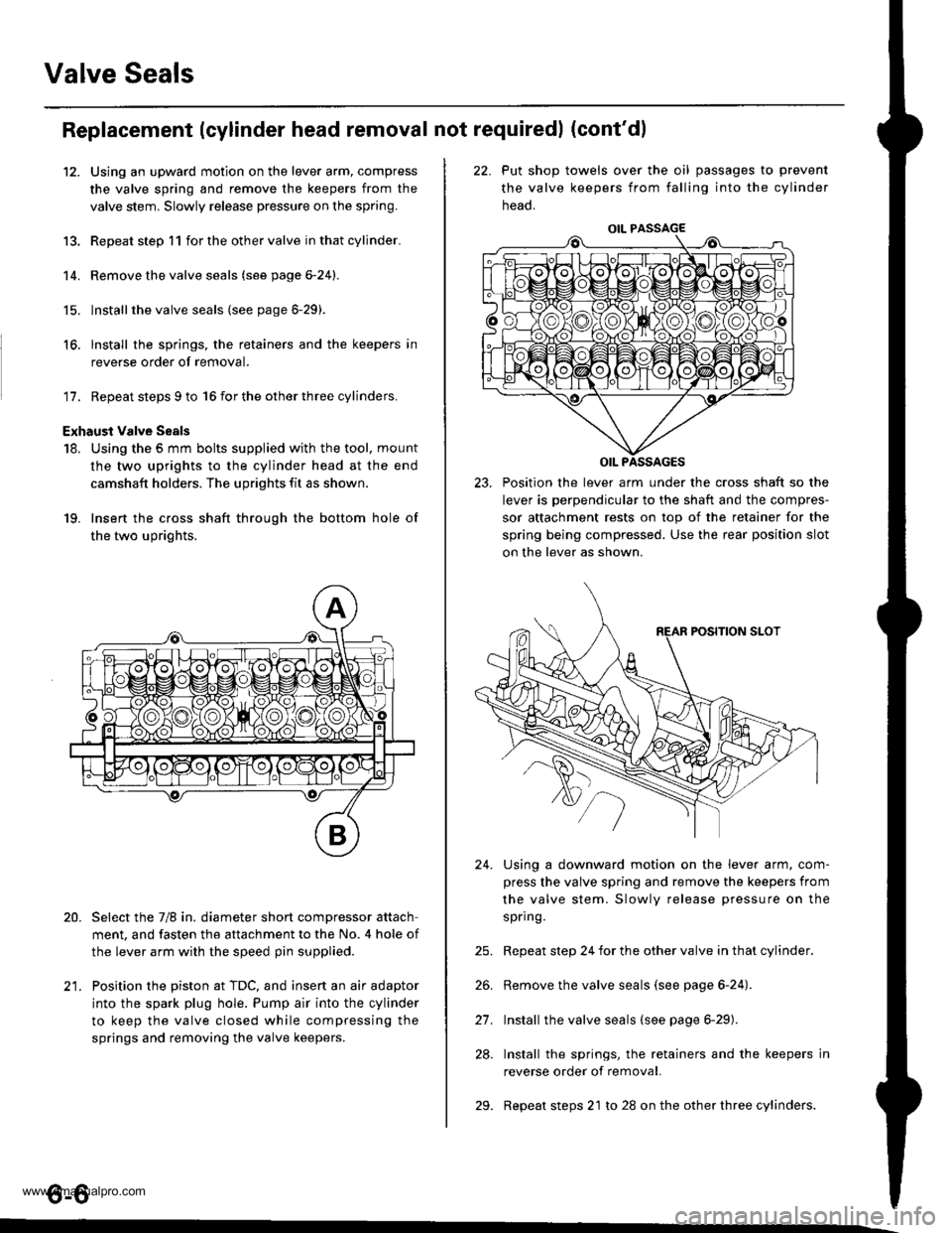
Valve Seals
12.
Replacement (cylinder head removal not requiredl (cont'dl
Using an upward motion on the lever arm, compress
the valve spring and remove the keepers from the
valve stem. Slowly release pressure on the spring.
Repeat step 11 for the other valve in that cylinder.
Remove the valve seals (see page 6-24).
Installthe valve seals (see page 6-29).
lnstall the springs, the retainers and the keepers in
reverse order of removal.
'17. Repeat steps 9 to 16 for the other three cylinders.
Exhaust valve Seals
18. Using the 5 mm bolts supplied with the tool, mount
the two uprights to the cylinder head at the end
camshaft holders. The uprights fit as shown.
19. Insert the cross shaft through the bottom hole of
the two uprights.
Select the 7/8 in. diameter short compressor attach
ment, and fasten the attachment to the No. 4 hole of
the lever arm with the speed pin supplied.
Position the piston at TDC, and insert an air adaptor
into the spark plug hole. Pump air into the cylinder
to keep the valve closed while compressing the
springs and removing the valve keepers.
13.
14.
15.
16.
20.
t1
22. Put shop towels over the oil passages to prevent
the valve keepers from falling into the cylinder
neao.
23. Position the lever arm under the cross shaft so the
lever is perpendicular to the shaft and the compres-
sor attachment rests on top of the retainer for the
spring being compressed. Use the rear position slot
on the lever as shown.
Using a downward motion on the lever arm, com-
press the valve spring and remove the keepers from
the valve stem. Slowly release pressure on the
spring.
Repeat step 24 for the other valve in that cylinder.
Remove the valve seals (see page 6-24).
Install the valve seals (see page 6-29).
Install the springs, the retainers and the keepers in
reverse order of removal.
Repeat steps 21 to 28 on the other three cylinders.
24.
21.
28.
29.
o-o
www.emanualpro.com
Page 132 of 1395

13. Remove the upper radiator hose, heater hose and
water bypass hose.
WATER BYPASS
UPPEBRADIATORHOSE
17
HEATERHOSE
Remove the engine wire harness connectors and
wire harness clamps from the cylinder head and the
intake manifold.
o Four fuel injector connectors
. Engine coolant temperature (ECT) sensor con-
neclor
. Radiator fan switch connector
. Coolant temperature gauge sendlng unlt connec-
tor
. Throttle position sensor connector
. Manifold absolute pressure {MAP) sensor con-
nector
Primary heated oxygen sensor (primary HO2S)
connector
ldle air control (lAC) valve connector
Distributor connector
Remove the spark plug caps and distributor from the
cylinder head.
Remove the cruise control actuator (see section 4).
Support the engine with a jack, then remove the
upper bracket. Make sure to place a cushion
between the oil pan and the iack (see page 6-10).
a
18. Remove the cylinder head cover.
19. Inspect the timing belt (see page 6-9).
CYLINDER
(cont'd)
6-19
www.emanualpro.com
Page 140 of 1395
Cylinder Head
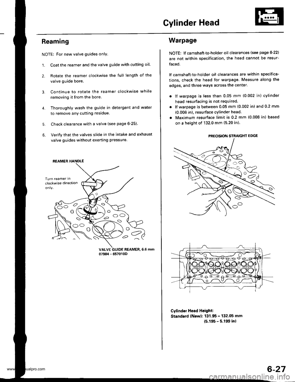
Reaming
NOTE: For new valve guides only.
1. Coat the reamer and the valve guide with cutting oil.
2. Rotate the reamer clockwise the full length of the
valve guide bore.
Continue to rotate the reamer clockwise while
removing it from the bore.
Thoroughly wash the guide in detergent and water
to remove anY cutting residue.
Check clearance with a valve (see page 6-25).
Verify that the valves slide in the intake and exhaust
valve guides without exerting pressure.
3.
4.
5.
6.
vALvE GUIDE REAMER,6.6 mm0798i1 - 657010O
REAMER HANDLE
e
Warpage
NOTE: lf camshaft-to-holder oil clearances (see page G22)
are not within specification, the head cannot be resur-
faced.
lf camshaft-to-holder oil clearances are within specifica-
tions, check the head for warpage. Measure along the
edges, and three ways across the center.
. if warpage is less than 0.05 mm (0.002 in) cylinder
head resurfacing is not required
lf warpage is between 0.05 mm (0.002 in) and 0.2 mm
(0.008 in), resurface cylinder head.
Maximum resurface limit is 0.2 mm (0.008 in) based
on a height of 132.0 mm (5.20 in).
Cylind€r Hesd Height:
Standard {New}: 131.95 - 132.05 mm
15.195 - 5.199 inl
PRECISION STRAIGHT EDGE
6-27
www.emanualpro.com
Page 171 of 1395
Engine Lubrication
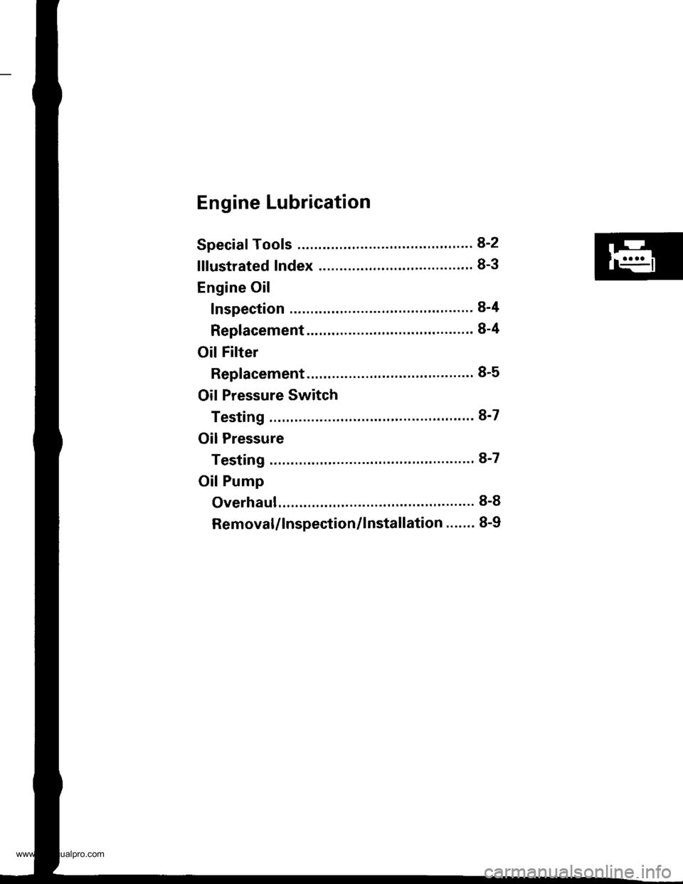
Speciaf Tools .......... ...".""'8-2
lllustrated Index ........... .'...8-3
Engine Oil
Inspection ............'..'...'..' 8-4
Replacement ............................'........... 8-4
OilFilter
Rep1acement........................................ 8-5
Oil Pressure Switch
Testing ".....8-7
Oil Pressure
Testing ....'.' 8-7
OilPump
Overhaul..... ...........,......... 8-8
Removal/lnspection/lnstallation ....'.' 8-9
www.emanualpro.com
Page 173 of 1395
lllustrated Index
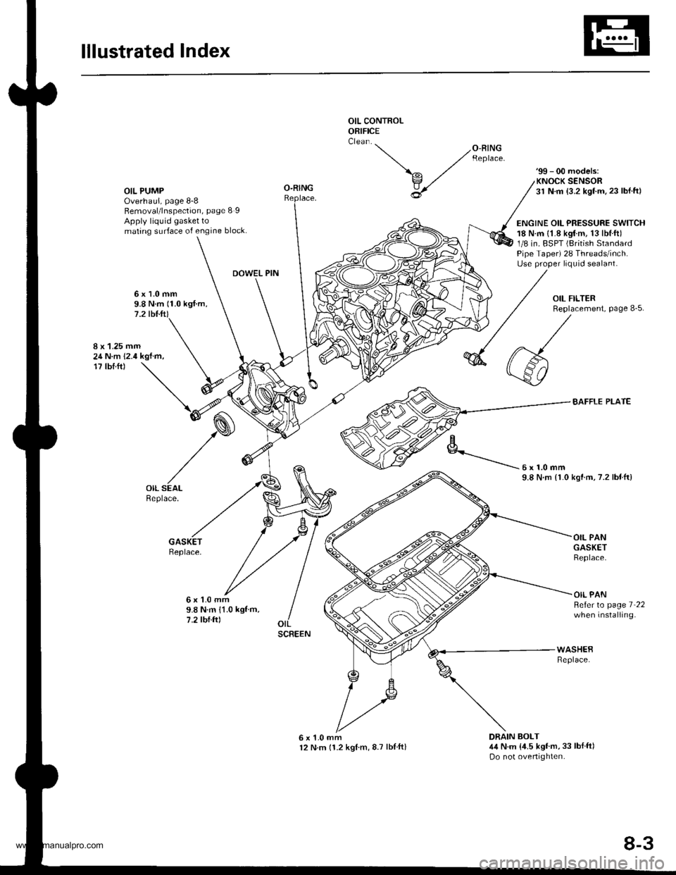
OIL CONTROLORIFICE
OIL PUMPOverhaul, page 8-8Removal/lnspection, page 8 IApply liquid gasket tomating surface of engine block.
'99 - 00 models:KNOCK SENSOR31 N.m {3.2 kgf.m.23 lbl.ft)
ENGINE OIL PRESSURE SWITCH18 N.m {1.8 kgtm, 13lbl.ft)1/8 in. BSPT (British StandardPipe Taper) 28 Threads/inch.Use proper liquid sealant.
O-RING
DOWEL PIN
6x1.0mm9.8 N.m (1.0 kgf.m,7.2 tbl.ft)
8 x 1.25 mm24 N.m 12.4 kgf.m,17 tbf.ft)
BAFFLE PLATE
kgtm,7.2 lbtftl
Replace.
6x1.0mm9.8 N.m 11.0 kgf m,7.2 tbf.ftl
OIL PANGASKETReplace.
OIL PANBeferto page 7 22when installing.
6x1.0mm12 N.m 11.2 kglm,8.7 lblftl
WASHEBReplace.
DRAIN BOLT4,1N.m {,1.5 kgf'm,33 lbf ft)Do not overtighten.
'-- /o-RrNG ,/ Reptace.
\^ ./
v,/
U
6x1.0mm9.8 N.rn {1.0
SCREEN
8-3
www.emanualpro.com
Page 177 of 1395
Oil Pressure SwitchOil Pressure
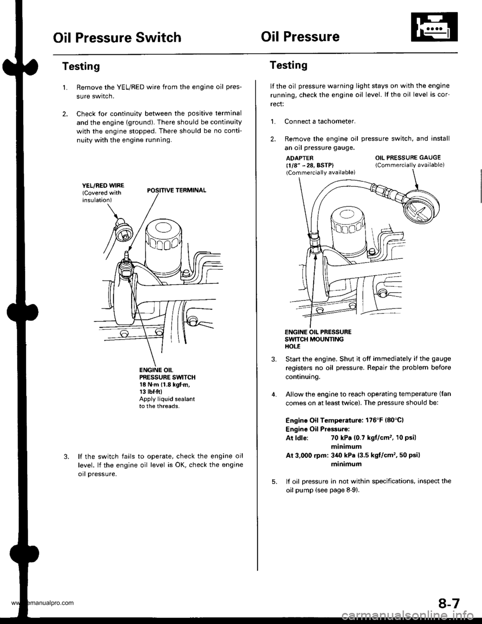
Testing
Remove the YEL/RED wire from the engine oil pres-
sure swrtcn.
Check for continuity between the positive terminal
and the engine {ground). There should be continuity
with the engine stopped. There should be no conti-
nuity with the engine running.
L
PRESSURE SWTCH18 N.m {1.8 kgf.m,13 tbr.ftlApply liquid sealantto the threads,
lf the switch fails
level. lf the engine
orl pressure.
to operate, check the engine oil
oil level is OK, check the engine
Testing
lf the oil pressure warning light stays on with the engine
running, check the engine oil level. lf the oil level is cor-
rect:
L Connect a tachometer.
2. Remove the engine oil
an oil pressure gauge.
ADAPTER(1/8" - 28, BSTP)(Commercially available)
pressure switch. and install
OIL PRESSURE GAUGE
{Commercially available)
4.
ENGINE OIL PRESSURESWTTCH MOUNNNGHOt-E
Start the engine. Shut it off immedjately if the gauge
registers no oil pressure. Repair the problem before
continuing.
Allow the engine to reach operating temperature (fan
comes on at least twice). The pressure should be:
Engino Oil Temperature: 176'F (80'C)
Engine Oil Pressure:
At ldle:70 kPa (0.7 kgt/cm'�, 10 psil
minimum
Ai 3,000 rpm: 3/r0 kPa {3.5 kgt/cm', 50 psi)
minimum
lf oil pressure in not within specifications, inspect the
oil pump (see page 8-9).
8-7
www.emanualpro.com