shield HONDA CR-V 1999 RD1-RD3 / 1.G Owner's Manual
[x] Cancel search | Manufacturer: HONDA, Model Year: 1999, Model line: CR-V, Model: HONDA CR-V 1999 RD1-RD3 / 1.GPages: 1395, PDF Size: 35.62 MB
Page 1078 of 1395
Wiper/Washer
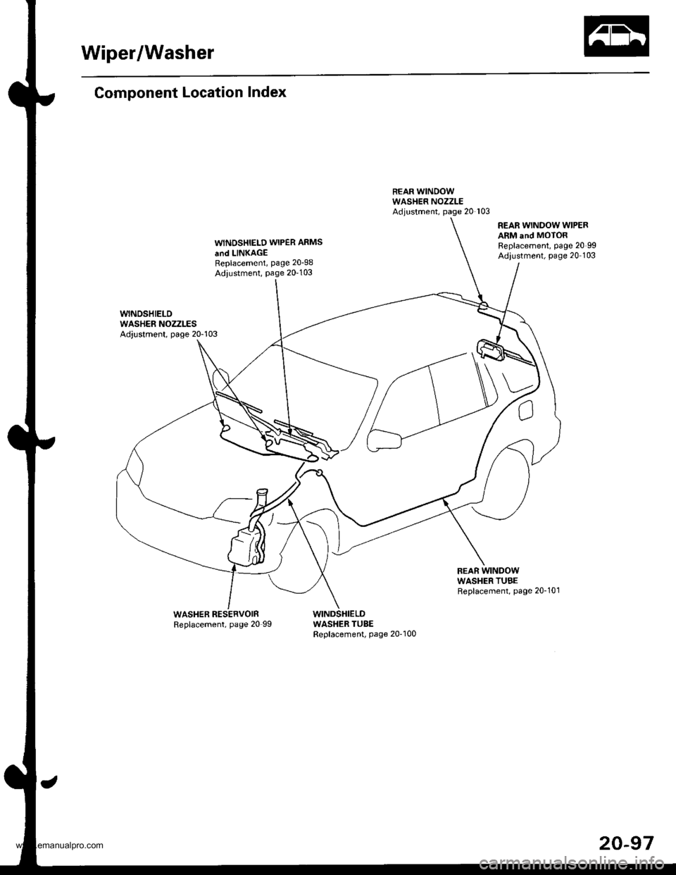
Component Location Index
WINOSHIELD WIPER ARMS
and LINKAGEReplacement, page 20-98
Adiustment, Page 20-103
REAR WINDOW WIPERARM and MOTORReplacement, page 20 99Adiustment, page 20 103
WASHER RESERVOINReplacement, page 20 99WASHER TUBEReplacement, page 20-100
20-97
www.emanualpro.com
Page 1079 of 1395
Wiper/Washer
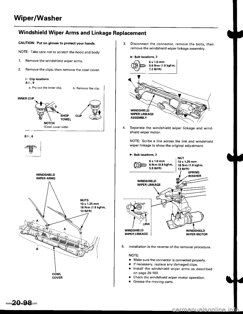
Windshield Wiper Arms and Linkage Replacement
CAUTION: Put on gloves to protoct your hands.
NOTE: Take care not to scratch the hood and body.
1. Remove the windshield wiper arms.
2. Remove the clips, then remove the cowl cover.
>: Clip locationsA>.9
b. Remove the clip.
SHOPTOWEL
(Cowl cover side)
/G
"rr/ &
a. Pry out the anner clip.
INNER CLIP
B>.8
ql
WINDSHIELDWIPER ARMS
NUTS'10 x 1.25 mm18 N.m 11.8 kgf.m.13 tbf.ftl
COVER
20-98
3. Disconnect the connector, remove the bolts, then
remove the windshield wiper linkage assembly.
>: Boh locations,3
4. Separate the windshield wiper linkage and wind-shield wiper motor.
NOTE: Scribe a line across the link and windshieldwiper linkage to show the original adjustment.
>: Boh locations, 3
s}@
1ffi,
/Y{
/
' L|NK
WINDSHIELDWIPER LIN(AGEWIPER MOTOR
5. Installation is the reverse of the removal procedure.
NOTE:
. Make sure the connector is connected properly.. lf necessary. replace any damaged clips.. Install the windshield wiper arms as describedon page 20-103.
. Check the windshield wiper motor operation.. Grease the moving parts.
6x1.0mm9.8 N.m (1.0 kglm,7.2 tbt.fr)
6x1.0mm8 N.m 10.8 kgf.m,5.8 lbf.ftl
NUT10 x 1.25 mm18 N.m 11.8 kgf.m,13 tbf.ftlSPRINGWASHER
www.emanualpro.com
Page 1081 of 1395
Wiper/Washer
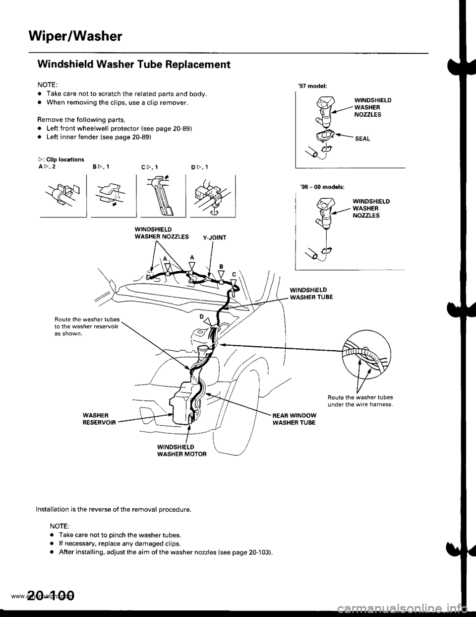
Windshield Washer Tube Replacement
NOTE:
. Take care not to scratch the related parts and body.. When removing the clips, use a clip remover.
Remove the following parts.
. Left front wheelwell protector (see page 20-89). Left inner fender (see page 20-89)
WINDSHIELOWASHER NOZZLES Y-JOINT
Boute the w6sher tubesto the washer reservoir
'97 model:
63'fr{-------
ax---\J
,.&--
\7>: Clip locationsA >,2 B >,1c>, 1D>,1
\
lnstallation is the reverse of the removal procedure.
NOTE:
. Take care not to pinch the washer tubes.
. lf necessary, replace any damaged clips.. After installing, adjust the aim ofthe washer nozzles (see page 20-103).
20-100
www.emanualpro.com
Page 1082 of 1395
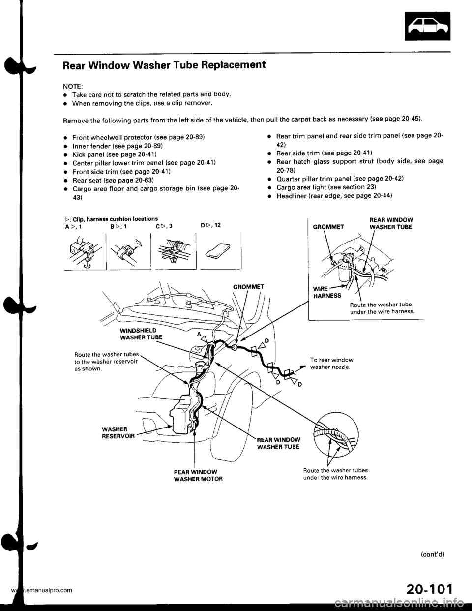
Rear Window Washer Tube Replacement
NOTE:
. Take care not to scratch the related parts and body.
. When removing the clips, use a clip remover.
Remove the following parts from the left side of the vehicle, then
. Front wheelwell protector (see page 20-89)
. Innertender (see page 20-89)
. Kick panel (see page 20-4't)
. Center pillar lower trim panel (see page 20-41)
. Front side trim (see page 20-41)
. Rear seat (see page 20-63)
a Cargo area floor and cargo storage bin (see page 20-
43)
>: Clip, harness cu3hion location3c>,3D>,12A>, 1B>, 1
Route the washer t!be
under the wire harness
Route the washer tubesto the washer reservoir
WASHEBRESERVOIR
wasner no2zre.
@s_l el 4
WINDSHIELDWASHEB TUBE
REAR WINDOWWASHER MOTOR
GROMMET
wrNoowWASHER TUBE
pull the carpet back as necessary (see page 20-45)
. Rear trim panel and rear side trim panel (see page 20-
42J
. Rear side trim (see page 20-41)
. Rear hatch glass support strut (body side, see page
20-7Al
. Ouarter pillartrim panel (see page 20-421
o Cargo area light (see section 23)
. Headliner (rear edge, see page 20-44)
GROMMET
(cont'd)
20-101
www.emanualpro.com
Page 1176 of 1395
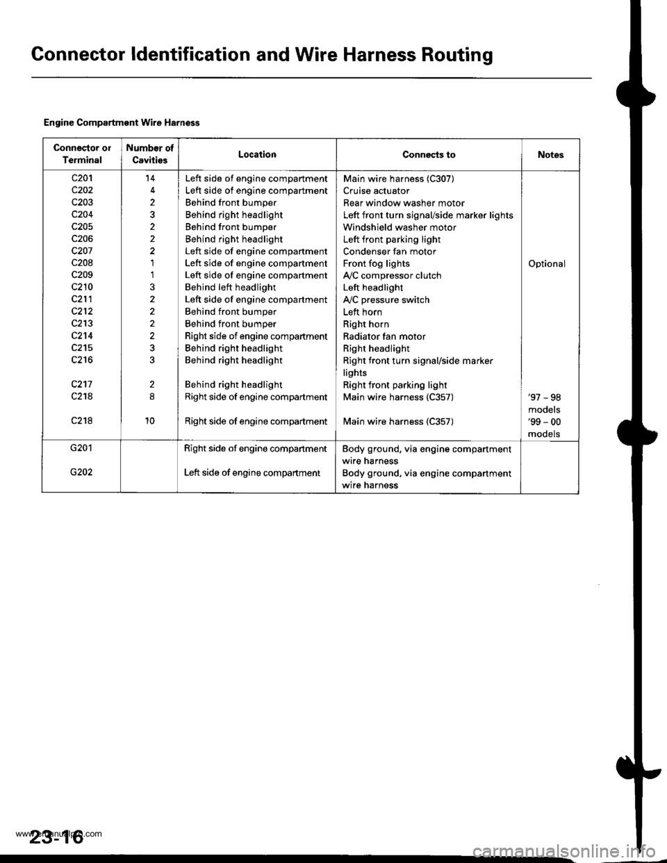
Gonnector ldentification and Wire Harness Routing
Engine Compartment Wire Harness
Connector ol
Terminal
Number of
CavitiesLocationConnects toNotes
c20'l
c202
c203
c204
c205
c206
c207
c208
c209
c210
c212
c213
c2't4
c215
c216
c217
c21A
c218
14
2
2
1'l
2
10
Left side of engine compartment
Left side of engine compartment
Behind front bumper
Behind right headlight
Behind front bumper
Behind right headlight
Left side of engine compartment
Left side of engine compartment
Left side of engine compartment
Behind left headlight
Left side of engine compartment
Behind front bumper
Behind front bumper
Right side of engine compartment
Behind right headlight
Behind right headlight
Behind right headlight
Right side of engine compartment
Right side of engine compadment
Main wire harness (C307)
Cruise actuator
Rear window washer motor
Left front turn signal/side marker lights
Windshield washer motor
Left front parking light
Condenser fan motor
Front fog lights
IVC compressor clutch
Left headlight
IVC pressure switch
Left horn
Right horn
Radiator fan motor
Right headlight
Right front turn signal/side marker
lights
Right front parking light
Main wire harness 1C357)
Main wire harness (C357)
Optional
'97 - 98
models'99 - 00
mooets
G201
G202
Right side of engine companment
Left side of engine compartment
Body ground, via engine compartment
wire harness
Body ground, via engine compartment
wire harness
23-16
www.emanualpro.com
Page 1178 of 1395
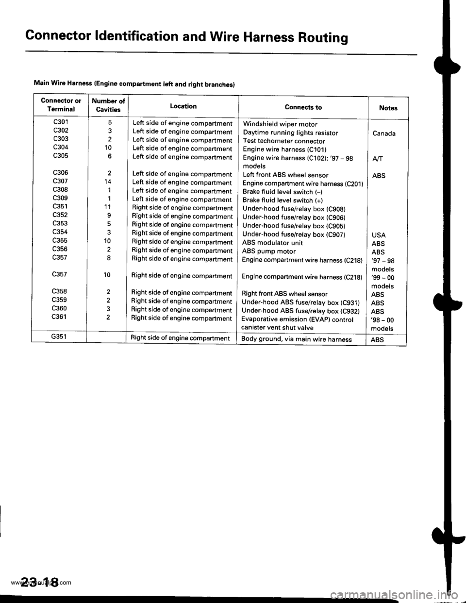
Gonnector ldentification and WireHarness Routing
Main Wire Harness lEngine compartmont left and right branches)
Connectot ol
Terminal
Number ot
CavitiesLocationConneqts toNot€s
c301
c303
c304
c305
c306
c307
c308
c309
c352
c354
c356
c357
c358
c359
c360
LJO I
5
2
10
'14
1
1
t1
3
10
8
10
2
Left side of engine compartment
Left side of engine compartment
Left side of engine compartment
Left side of engine companment
Left side of engine compartment
Left side of engine compartment
Left side of engine compartment
Left side of engine compartment
Left side of engine compartment
Right side of engine compartment
Right side of engine compartment
Right side of engine compartment
Right side of engine compartment
Right side of engine compartment
Right side of engine compartment
Right side of engine compartment
Right side of engine compartment
Right side of engine compartment
Right side of engine compartment
Right side of engine compartment
Right side of engine compartment
Windshield wiper motor
Daytime running lights resistor
Test techometer connector
Engine wire harness (C10])
Engine wire harness (C102): '97 - 98models
Left front ABS wheel sensor
Engine compartment wire harness (C201)
Brake fluid level switch {-)Brake fluid level switch (+)
Under-hood fuse/relay box (C908)
Under-hood fuse/relay box (C906)
Under-hood fuse/relay box (C905)
Under-hood fuse/relay box (C907)
ABS modulator unit
ABS pump motor
Engine compartment wire harness (C218)
Engine compartment wire harness (C218)
Right front ABS wheel sensor
Under-hood ABS fuse/retay box (C931)
Under-hood ABS fuse/relay box (C9321
Evaporative emission (EVAP) controcanister vent shut valve
Canada
ABS
USA
ABS
ABS'97 - 98
models'99 - 00
mooets
ABS
ABS
ABS'98 - 00
mooets
G35lRight side of engine compartmentBody ground, via main wire harnessABS
23-18
www.emanualpro.com
Page 1205 of 1395
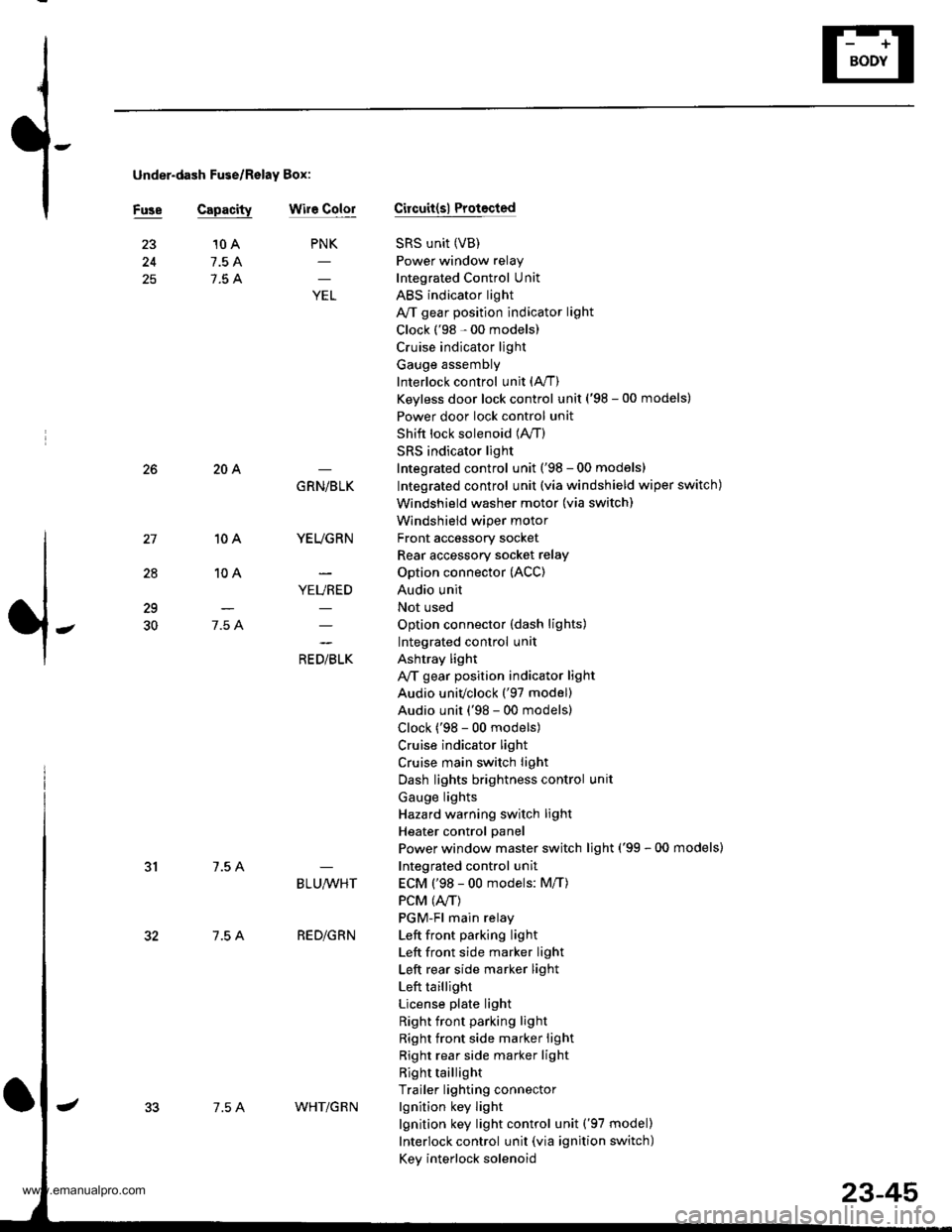
under-dash Fuse/Relay Box:
Fuse Capacitywir6 ColorCircuit(sl Protocted
SRS unit (VB)
Power window relay
Integrated Control Unit
ABS indicator light
A/T gear position indicator light
Clock ('98 - 00 models)
Cruise indicator light
Gauge assembly
Interlock control unit (A,/T)
Keyless door lock control unit ('98 - 00 models)
Power door lock control unit
Shift lock solenoid (lVT)
SRS indicator light
Integrated control unit ('98 - 00 models)
Integrated control unit (via windshield wiper switch)
Windshield washer motor (via switch)
Windshield wiper motor
Front accessory socket
Rear accessory socket relay
Option connector (ACC)
Audio unit
Not used
Option connector (dash lights)
Integrated control unit
Ashtray light
A,/T gear position indicator light
Audio univclock ('97 model)
Audio unit ('98 - 00 models)
Clock ('98 - 00 models)
Cruise indicator light
Cruise main switch light
Dash lights brightness control unit
Gauge lights
Hazard warning switch light
Heater control panel
Power window master switch light ('99 - 00 models)
Integrated control unit
ECM ('98 - 00 models: M/T)
PCM (4./T)
PGM-Fl main relay
Left front pa.king light
Left front side marker light
Left rear side marker light
Left taillight
License plate light
Right front parking light
Right front side marker light
Right rear side marker light
Right taillight
Trailer lighting connector
lgnition key light
lgnition key light control unit ('97 model)
Interlock control unit (via ignition switch)
Key interlock solenoid
25
PNK
;
10 A
7.5 A
7.5 A
28
10A
10A
7.5 A
204
7.5 A
7.5 A
GRN/BLK
YEUGRN
YEURED
a, olrL"
29
30
BLU,ryVHT
RED/GRN
7.5 AWHT/G R N
23-45
www.emanualpro.com
Page 1206 of 1395

Ground Distribution
Ground-to-Component(sl Index
GroundWire Color
G2
G3
G 10'l
G201
G202
G351
BLIVRED
BRN
BLK
BLK
BRN/BLK
BLK
BLK
BLK
23-46
Component or Circuits Grounded
Battery
Valve Cover
Transmission housing
A,/T gear position switch
ECM (PG1, PG2) ('98 - 00 models: M/T)
PCM (PG1, PG2l (Avrr)
PGM-FI main relay
Power steering pressure (PSP) switch
Radiator fan switch
VSS
Data link connector
ECM (1G1, LG2) ('98 - 00 models: M/T)
PCM (LGI, LG2) (IVT)
Shielding:
between ECM ('98 - 00 models: M/T) or PCM (Ay'T) and CKF sensorbetween ECM {'98 - 00 modets: M/T} or pCM (Ay'T) and CKp sensorbetween ECM ('98 - 00 models: M/T) or PCM (rVT) and CYP sensorbetween ECM ('98 - 00 models: M/T) or PCM (Ay'T) and TDC sensorbetween ECM {'98 - 00 models: M/T) or PCM (ly'T) and countershaft speed sensor (Ay'T)
between ECM ('98 - 00 models: M/T) or PCM {A,,/T) and mainshaft sp€ed sensor {!VT)between ECM ('98 - 00 models: M/T) or PCM (A,/T) and primary HO2Sbetween ECM ('98 - 00 models: M/T) or PCM (Ay'T) and secondary HO2SHorn (High)
Horn {Low}
Radiator fan motor
Right headlight
Right front parking light
Right front side marker light
Right front turn signal light
Condenser fan motor
Cruise actuator
Left front parking light
Left front side marker light
Left front turn signal light
Left headlight
Rear window washer motor
Windshield washer motor
ABS pump motor
www.emanualpro.com
Page 1207 of 1395

BLKG401
GroundWir€ ColorComponent or Circuits Grounded
ABS indicator circuit
ABS control unit
Ashtray light
A/T gear position indicator dimming circuit
Brake fluid level switch
Clock ('98 - 00 models)
Clutch inrerlock switch (M/T)
Clutch switch (Mff)
Cruise main switch
Cruise indicator circuit
Cruise control unit
Dash lights brightness controller
Data iink connector
Daytime running rights control unit (Canada)
Front accessary socket
Gauge and indicators
Heater control panel
lgnition key light control unit ('97 model)
lgnition key switch
Integrated control unit
Interlock control unit (Ay'T)
Parking pin switch {A,/T)
Power window relay
Rear accessary socket relay
Bear window defogger relay
Rear window wiper control unit ('97 model)
Service check connector
Spotlights
SRS indicator circuit
Turn signal/hazard relay
Windshield wiper motor
Windshield wiper/washer switch- plus everything grounded through G402
ABS control unit
Blower motor relay
Blower motor high relay
ELD unit (USA)
Power transistor- plus everything grounded through G401
BLKG402
{cont'd)
23-47
www.emanualpro.com
Page 1210 of 1395
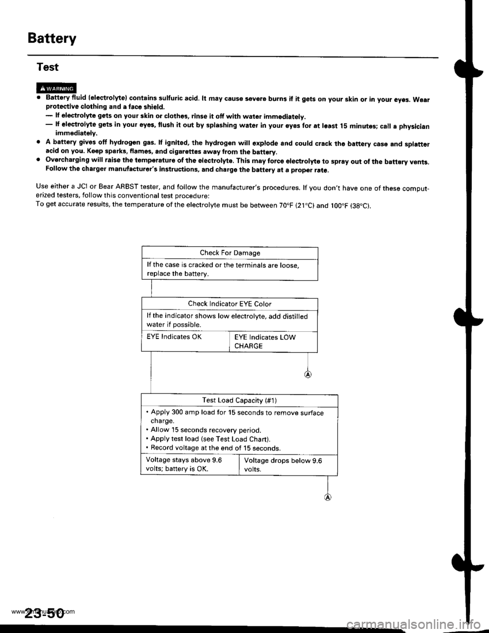
Battery
Test
@M. Battery fluid (eleqtrolyte) contains sulturic acid. lt may couse sevore burns if it gets on your skin or in your eyes. Wearprotective clothing and a fac6 shield.- lf elestrolyte gets on your skin o. clothos, rinse it otf with wator imm€diately.- lf €leqtrolyte gets in your eyes. tlush it out by splashing water in your syes for at least 15 minutes; call a physicianimmediately.
. A battery gives off hydrogon gas. lf ignited, the hydrogen will €xplode and could crack the battery case and splatt€racid on you. Kgop sparks. flamss, and cigarettes away from the batt€ry,. Overcharging will raise the tomperatute of the electrolyte. This may torcs electrolyto to spray out of the battEry vents,Follow the charger manutacturer's instructions, and charge the battery at a proper ral€,
Use either a JCI or Bear ARBST tester, and follow the manufacturer's procedures. lf you don't have one of tnese comput-erized testers, follow this conventional test procedure:
To get accurate results, the temperature ofthe electrolyte must be between 70.F (21.c) and loo"F (38"c).
23-50
lf the case is cracked or the terminals are roose.
replace the batterv.
Check Indicator EYE Color
lf the indicator shows low electrolyte, add distilled
water if possible.
EYE Indicates OK
Test Load Capacity (#1)
. Apply 300 amp load for 15 seconds to remove surfacecharge.. Allow 15 seconds recovery period.. Apply test load (see Test Load Chart).. Record voltage at the end of 15 seconos.
Voltage stays above 9.6
volts; battery is OK.
www.emanualpro.com