connector a HONDA CR-V 1999 RD1-RD3 / 1.G Workshop Manual
[x] Cancel search | Manufacturer: HONDA, Model Year: 1999, Model line: CR-V, Model: HONDA CR-V 1999 RD1-RD3 / 1.GPages: 1395, PDF Size: 35.62 MB
Page 1141 of 1395
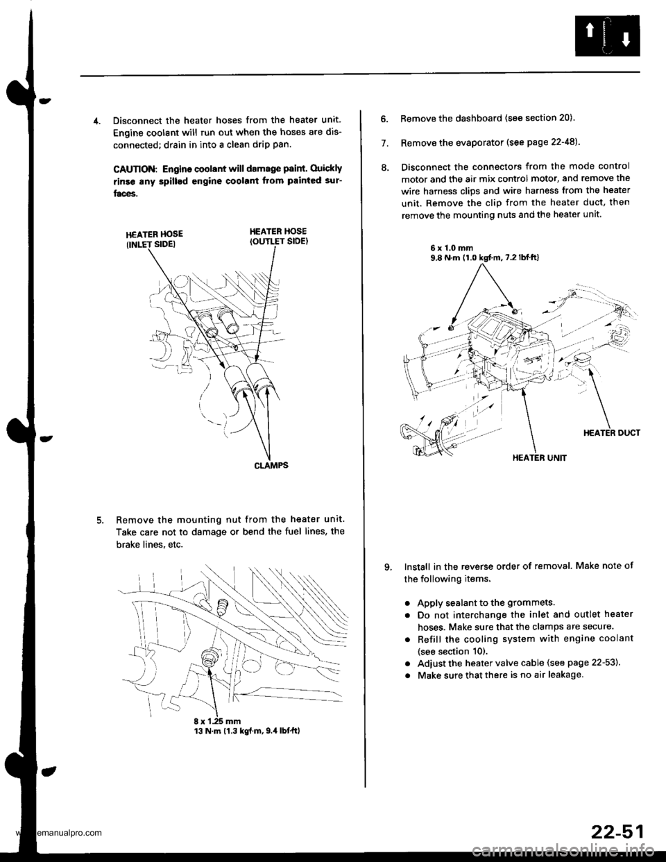
4. Disconnect the heater hoses from the heater unit.
Engine coolant will run out when the hoses are dis-
connected; drain in into a clean drip pan.
CAUTION: Engino coolant will damage p8int. Ouickly
rinse any spill€d engine coolant Itom painted sur-
faces.
HEATER HOSEIOUTLET SIDE)
Remove the mounting nut from the heater unit.
Take care not to damage or bend the fuel lines, the
brake lines. etc.
CLAMPS
13 N.m 11.3 kg{.m,9.4 lbtftl
22-51
7.
ll.
Remove the dashboard (see section 20).
Remove the evaporator (see page 22-48).
Disconnect the connectors from the mode control
motor and the air mix control motor, and remove the
wire harness clips and wire harness from the heater
unit. Remove the clip from the heater duct, then
remove the mounting nuts and the heater unit
6x1.0mm9,8 N.m (1.0 kgt m,7.2lblft)
qInstall in the reverse order of removal. Make note of
the following items.
a
a
a
a
Apply sealant to the grommets.
Do not interchange the inlet and outlet heater
hoses. Make sure that the clamps are secure.
Refill the cooling system with engine coolant
{see section 10).
Adiust the heater valve cable (see page 22-53).
Make sure that there is no air leakage.
HEATER UNIT
www.emanualpro.com
Page 1152 of 1395
Compressor
Replacement
lf the compressor is marginally operable. run the
engine at idie speed, and let the air conditioner
work for a few minutes. then shut the engine off.
Disconnect the negative cable from the battery.
Recover the refrigerant with a recovery/recycling/
charging station (see page 22-59).
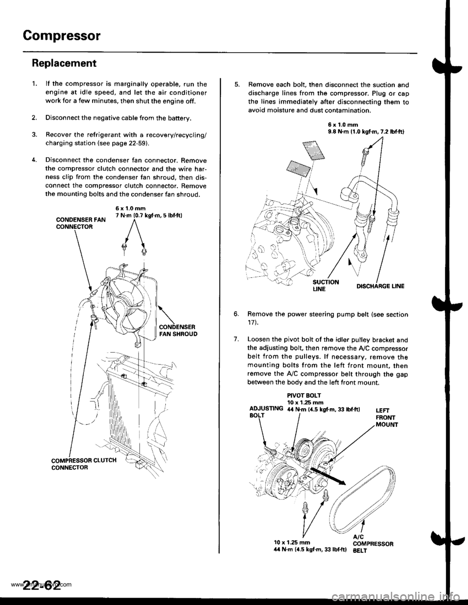
Disconnect the condenser fan connector. Remove
the compressor clutch connector and the wire har-
ness clip from the condenser fan shroud, then dis-
connect the compressor clutch connector. Remove
the mounting bolts and the condenser fan shroud,
CONDENSER FANCONNECTOR
6x1.0mm7 N.m 10.7 kg{.m, 5 lbl.ftl
'L
2.
5. Remove each bolt, then disconnect the suction and
discharge lines from the compressor. Plug or cap
the lines immediately after disconnecting them to
avoid moisture and dust contamination,
6x1.0mm9.8 N.m 11.0 kgf.m,7.2 lbf.ft)
DISCHARGE LINE
Remove the power steering pump belt (see section
17t.
Loosen the pivot bolt of the idler pulley bracket and
the adiusting bolt, then remove the Ay'C compressor
belt from the pulleys. lf necessary, remove themounting bolts from the left front mount, thenremove the A,/C compressor belt through the gap
between the bodv and the left front mount.
6.
7.
PIVOT BOLT10 x 1.25 mmAIUUSTING 4,t N.m (4.5 kgf.m, 33 tbf.ftlt€FTFRONTMOUltlT
10x 1.25 mm COMPRESSOR/t4 N.m (4.5 kgl.m,33 lbtftl BELI
LINE
www.emanualpro.com
Page 1155 of 1395
Clutch Inspection
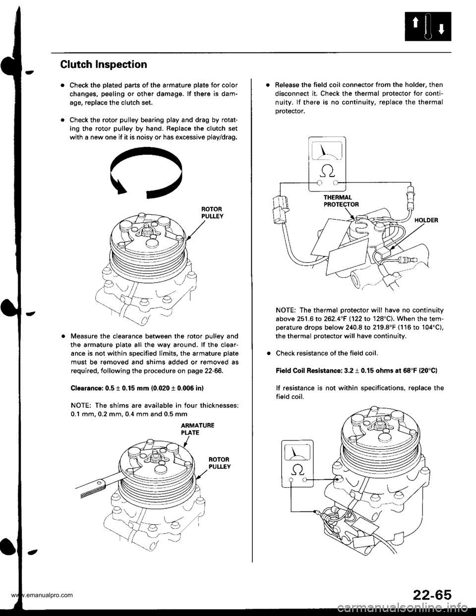
Check the plated parts of the armature plate for color
changes, peeling or other damage. lf there is dam-
age, replace the clutch set.
Check the rotor pulley bearing play and drag by rotat-
ing the rotor pulley by hand. Replace the clutch set
with a new one if it is noisy or has excessive play/drag.
Measure the clearance between the rotor pulley and
the armature plate all the way around. lf the clear-
ance is not within specified limits, the armature plate
must be removed and shims added or removed as
required, following the procedure on page 22-66.
Cloarance: 0.5 t 0.15 mm {0.020 t 0.q)6 in)
NOTE: The shims are available in four thicknesses:
0.1 mm. 0.2 mm. 0.4 mm and 0.5 mm
ABMATUBE
ROTOR
. Release the field coil connector from the holder, then
disconnect it. Check the thermal protector for conti-
nuity, lf there is no continuity, replace the thermal
prorecror.
NOTE: The thermal protector will have no continuity
above 251.6 to 262.4"F 1122 to 128"C). When the tem-perature drops below 240.8 to 219.8"F (116 to 104'C),
the thermal protector will have continuity.
Check resistance of the field coil.
Field Coil Resistance: 3.2 i 0.15 ohms at 68"F {20'C)
lf resistance is not within specifications, replace the
field coil.
22-65
www.emanualpro.com
Page 1157 of 1395
l-
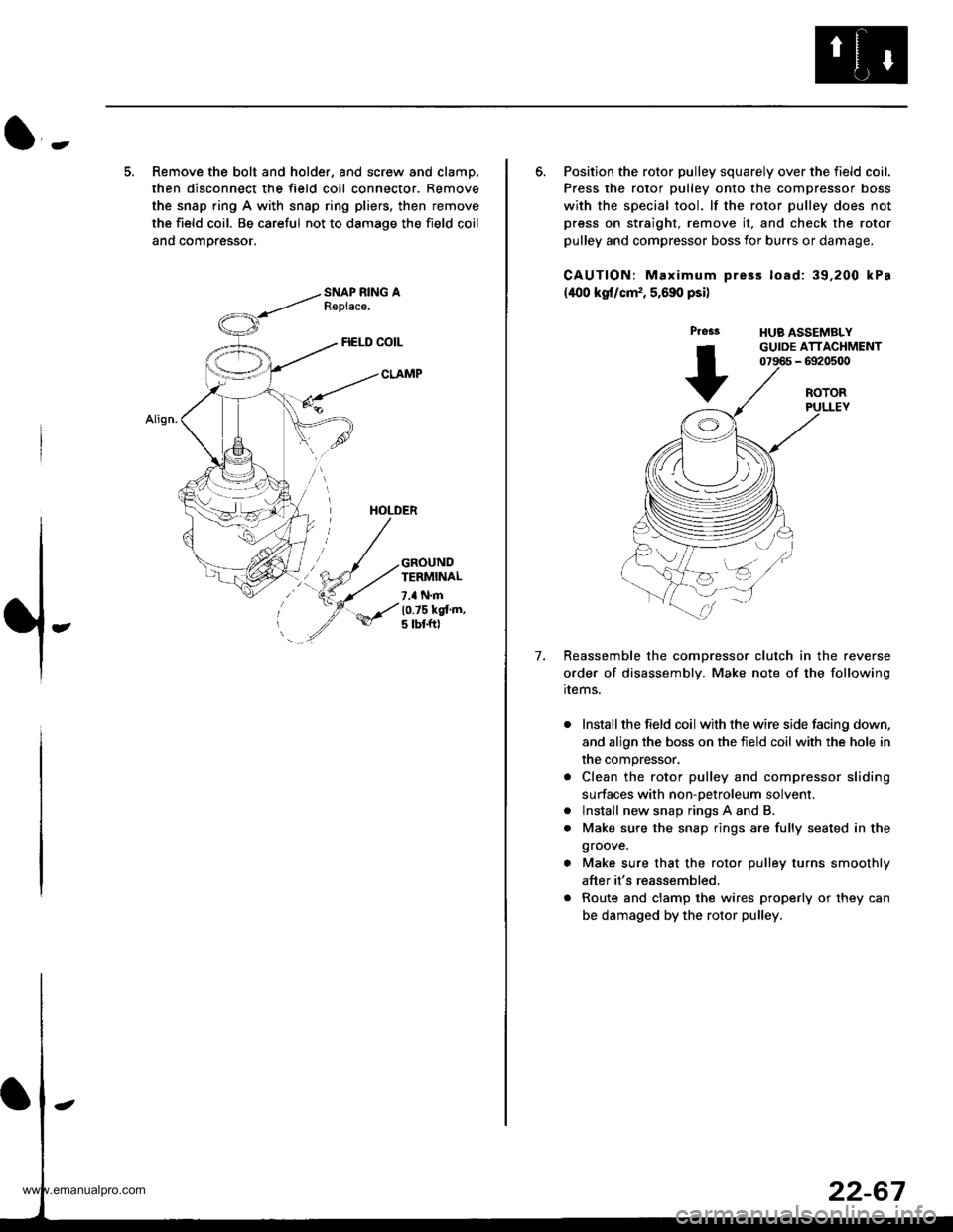
5. Remove the bolt and holder, and screw and clamp.
then disconnect the field coil connector. Remove
the snap ring A with snap ring pliers, then remove
the field coil. Be careful not to damage the field coil
and comoressor.
FIELD COIL
CLAMP
HOLDER
GROUNDTERMINAL
7,a N.m
10.75 kgt'm,5 tbt ftl
6. Position the rotor pulley squarely over the field coil.
Press the rotor pulley onto the compressor boss
with the special tool. lf the rotor pulley does not
press on straight, remove it, and check the rotor
pulley and compressor boss for burrs or damage.
CAUTION: Maximum pre3s load: 39,200 kPa
(400 kgf/cm,, 5,690 psi)
Press
+
HUB ASSEMBLYGUIDE ATTACHMENT07966 - 6920500
7.
ROTORPULLEY
Reassemble the comDressor clutch in the reverse
order of disassembly. Make note of the following
rrems.
Install the field coil with the wire side facing down,
and align the boss on the tield coil with the hole in
the compressor.
Clean the rotor pulley and compressor sliding
surfaces with non-oetroleum solvent.
lnstall new snap rings A and B.
Make sure the snap rings are fully seated in the
groove.
Make sure that the rotor pulley turns smoothly
after it's reassembled.
Route and clamp the wires properly or they can
be damaged by the rotor pulley.
a
a
www.emanualpro.com
Page 1158 of 1395
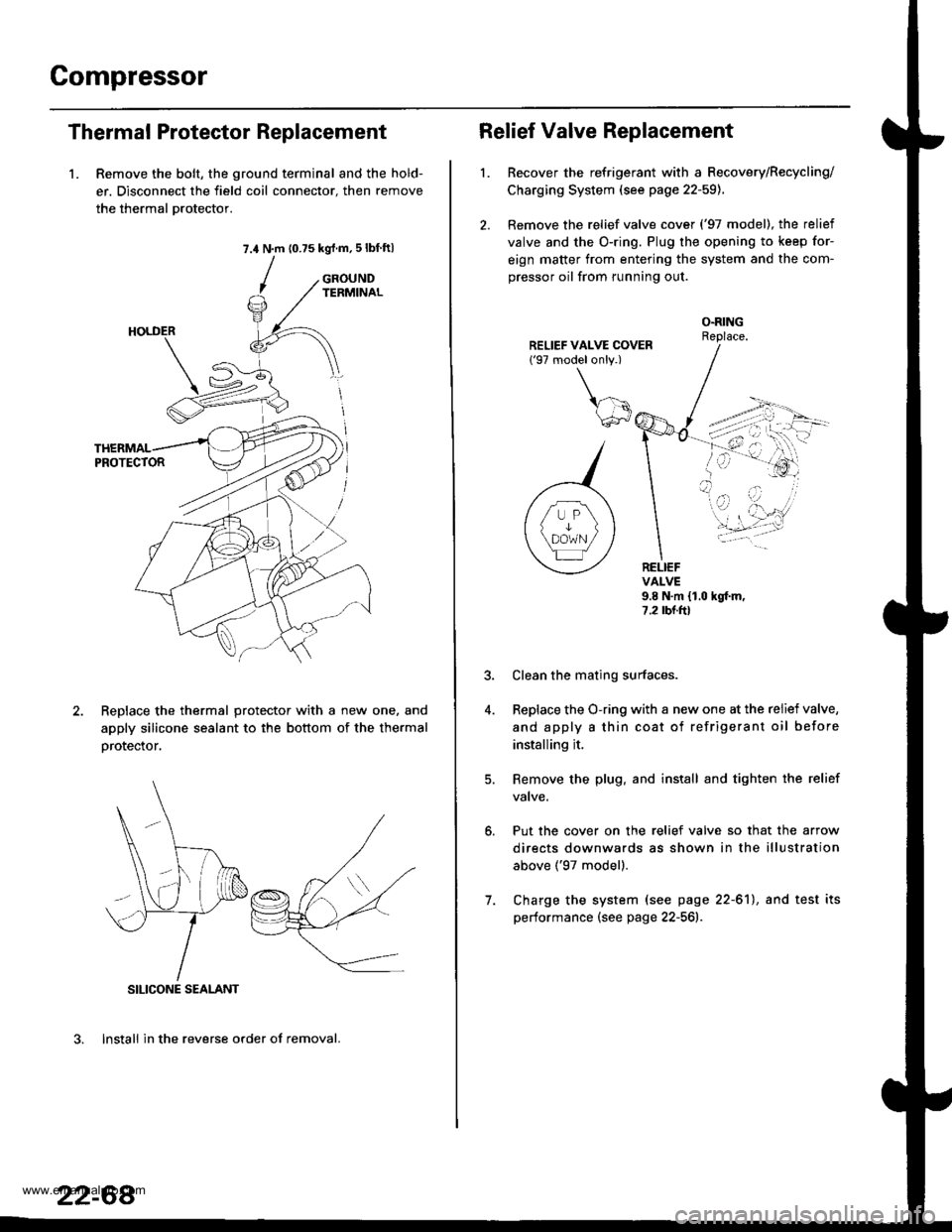
Compressor
Thermal Protector Replacement
1. Remove the bolt, the ground terminal and the hold-
er. Disconnect the field coil connector. then remove
the thermal Drotector.
7.4 N.m (0.75 kgrf.m,5lbf ftl
GROUNDTERMINAL
ReDlace the thermal protector with a new one, and
apply silicone sealant to the bottom of the thermal
orotector,
3. lnstall in the reverse order of removal.
SILICONE SEALANT
22-68
Relief Valve Replacement
l.Recover the refrigerant with a Recovery/Recycling/
Charging System (see page 22-59).
Remove the relief valve cover ('97 model), the relief
valve and the O-ring. Plug the opening to keep for-
eign matter from entering the system and the com-
pressor oil from running out.
O.RINGReplace.
RELIEFVALVE9.8 N.m {1.0 hgf.m,7.2 rbr.ftl
Put the cover on the relief valve so that the arrow
directs downwards as shown in the illustration
above ('97 model).
Clean the mating surfaces.
Replace the O-ring with a new one at the relief valve,
and apply a thin coat of refrigerant oil before
installing it.
Remove the plug. and install and tighten the relief
valve.
7. Charge the system (see page 22-61), and test its
performance (see page 22-561r.
www.emanualpro.com
Page 1161 of 1395

Body Electrical
Speciaf Toofs ,...,..,.............-.23-2
Troubleshooting
Tips and Precautions ......,.,..........,.................. 23-3
Five-step Troubleshooting ........,.,.,...,,.,......... 23-5
Wire Color Codes ...,....,.. 23-5
Relay and Control Unit Locations
Engine Compartment ..,.,......,......................... 23-6
Dashboard ,.,.,..............-.- 23-7
Door ....................... .........23-10
Index to Cilcuits and Sysiems
Accessory Socket .. ,....,.,..,.,. 23-95*Airbags ................ .,....,. Sestion 24
Air Conditioning ,.,.,.... Section 22
Alternator ................... Section 4
Anti-lock Brake System {ABSI ................... Section 19'A/T Gear Position Indicator ....................... Section 1,1
Automatic Transmission System ...........,.. Section 14
Battery ................... ..............23-50
Blower Controls .,...,.,, Section 22
Charging System ....... Seqtion il
Clock -'98 Model ................ 23-98
Connector ldentification and Wire HarnessRouting .................. ......... 23.11
Cruise Control ............ Ssction 4
Dash Lights Brightness Contlo||er ..................... 23-90
Fan Conlrols ...,......,.... Section 10
Fuel Pump ,..,.,...,....,.... Section 11
Fuses...................... .,,.,.,.,.,,.,23-40*Gauges
Circuit Diagram ......-....-..23-58
Fuel Gauge .....,.,..... Section 11
Speedometer ..,..........,... 23-56
Ground Distribution ,....,.,...23-46
Hatch Glsss ODenor .........................,.,.,.,.,..,.,.,.,,. 23-121
Heater Controls .-........ Soction 21*Horns.,...,..,.,.,....... ................23"104*fgnition Switch ,,.,.,..,.,.,,.,.,.,23-51
lgnition Key Light System -'97 Mod6l .............. 23.88
-+
BODY
www.emanualpro.com
Page 1163 of 1395
Troubleshooting
Tips and Precautions
Bef ore Troubleshootin g
. Check applicable fuses in the appropriate fuse/relay
box.
. Check the battery for damage, state of charge, and
clean. and tight connections.
. Check the alternator belt tension.
CAUTION:
. Do not quick-charge a battery unless the battery
ground cable has been disconnected, otherwise you
will damage the alternator diodes.
. Do not attempt to crank thc engins wilh the battery
ground cable loosely connected or you will severely
damage the wiring.
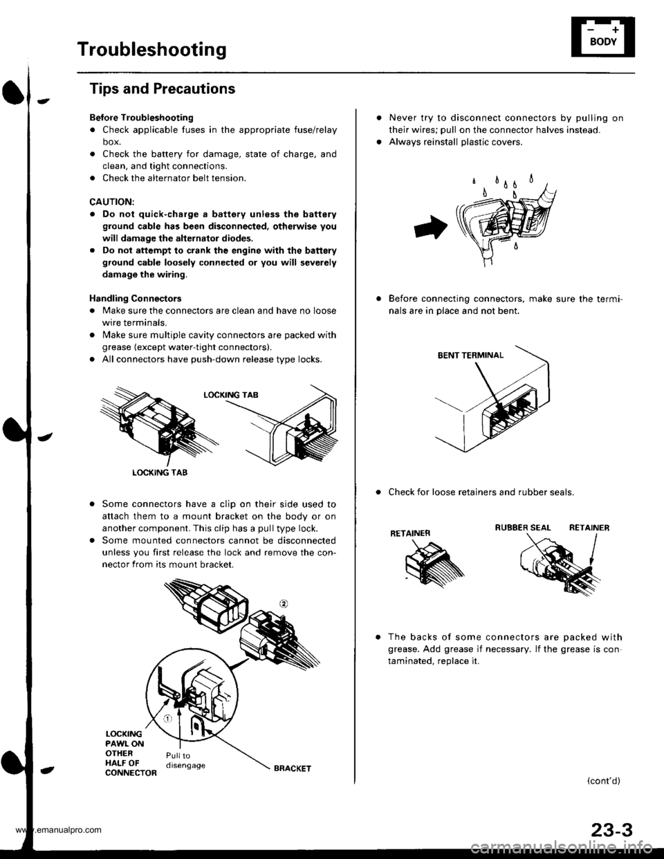
Handling Connestors
. Make sure the connectors are clean and have no loose
wire terminals,
. N4ake sure multiple cavity connectors are packed with
grease (except water-tight connectors).
. All connectors have push-down release type locks.
Some connectors have a clip on their side used to
attach them to a mount bracket on the body or on
another component. This clip has a pull type lock.
Some mounted connectors cannot be disconnected
unless you first release the lock and remove the con-
nector from its mount bracket.
LOCKINGPAWL ONOTHERHALF OFPulltodisengage
LOCKING TAB
CONNECTORBRACKET
Never try to disconnect connectors by pulling on
their wires; pull on the connector halves instead.
Alwavs reinstall olastic covers.
Before connecting connectors, make sure the termi-
nals are in place and not bent.
. Check for loose retainers and rubber seals.
RETAINER
The backs of some connectors are oacked with
grease. Add grease if necessary. lf the grease is con
taminated. reolace it.
{cont'd}
23-3
www.emanualpro.com
Page 1164 of 1395
Troubleshooting
Tips and Precautions (cont'dl
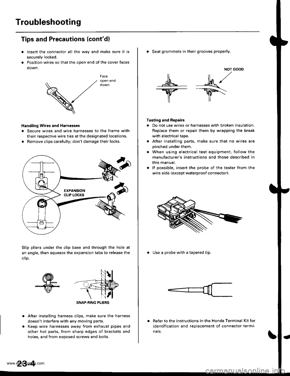
Insen the connector all the way and make sure it is
securely Iocked.
Position wires so that the open end of the cover faces
down.
V
Faceopen end
Handling Wires and Harnesges
. Secure wires and wire harnesses to the frame with
their respective wire ties at the designated locations.
. Remove clips carefully; don't damage their locks.
Slip pliers under the clip base and through the hole at
an angle, then squeeze the expansion tabs to release the
clrD.
After installing harness clips, make sure the harness
doesn't interfere with any moving pans.
Keep wire harnesses away from exhaust pipes and
other hot parts, trom sharp edges of brackets and
holes. and from exoos€d screws and bolts.
NOT GOOD
A -M/
lr lr*
T€sting and Repairs
. Do not use wires or harnesses with broken insulation.
Replace them or repair them by wrapping the break
with electricaltape.
. After installing parts, make sure that no wires are
pinched under them.
. When using electrical test equipment, follow the
manufacturer's instructions and those described in
this manual.
. lf possible, insert the probe of the tester from the
wire side (except waterproof connector).
. Seat grommets in their grooves properly.
. Use a probe with a tapered tip.
Refer to the instructions in the Honda Terminal Kit for
identification and replacement of connector termi-
nals.
www.emanualpro.com
Page 1171 of 1395

Gonnector ldentification and Wire Harness Routing
How to ldentity Connectors:
ldentification numbers have been assigned to all connectors, The number is preceded by the letter "C" for connectors.
"G" for ground terminals or "T" for non-ground terminals.
Location
HarnessEngine CompartmsntDashboardOthers lFloor, Door,
8oof, Tailgate)
Starter cableT1, T2 and @
Battery ground cableG1 and O
Engine ground cableT3
Transmission ground cableT4
G3
Engine wire harnessC101 through C137
T101 and T102
G101
Engine compartment ware harnessC201 through C218
G201 and G202
Under-hood ABS fuse/relay box
wire harness
t5ano9
Main wire harnessC301 through C309
C351 through C361
C401 through C447
G401 and G402
Dashboard wire harnessC501 through C524 (C525)
G501
Left side wire harnessC551 through C581
G551, G552 and G553
Right side wire harnessC601 through C605
lnterior wire harnessC701 through C703
Rear bumper wire harnessC641 through C643
Heater sub-harnessC731 through C740
Secondary heated oxygen sensor
sub-harness
C721 through C722
Combination switch sub-harnessC751 through C760
Driver's door wire harnessC661 through C667
Front passenger's door wire harnessC6Tl through C676
Left rear door wire harnessC681 through C684
Right rear door wire harnessC69'l through C694
Rear wire harnessC611 through C520
Tailgate wire harnessC631 through C634
G631
SRS main harnessC801 through C808
G801
High mount brake light sub-harnessC651 through C653
Fuel tank oressure sensor sub-harnessC645 through C647
www.emanualpro.com
Page 1172 of 1395
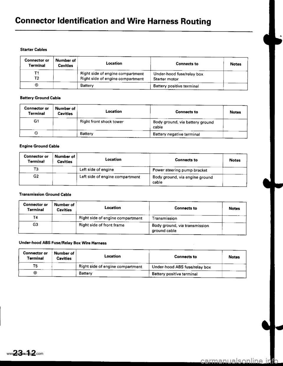
Connector ldentification and Wire Harness Routing
Connoctor or
Terminal
Number of
CavitiesLocationConnects toNotes
T1
r2
Right side of engine compartment
Right side of engine compartment
Under-hood fuse/relay box
Starter motor
oBatteryBattery positive terminal
Starter Cables
Battery Ground Cable
Connoctor or
Terminal
Number of
CavitiesLocationConneqts loNotes
GIRight front shock towerBody ground, via battery ground
cable
BatteryBattery negative terminal
Engine Ground Cable
Connector or
Terminal
Numb6r ol
CavitiesLocationConnects toNotes
T3Left side of enginePower steering pump bracket
Left side of engine compartmentBody ground. via engine ground
caote
Transmission Ground Cable
Connsstor o.
Terminal
Number of
CavitiesLocationConnects toNotes
T4Right side of engine compartmentTransmission
Right side of front frameBody ground, via transmissionground cable
Under-hood ABS Fuse/Relay Box Wire Harnsss
Conn6stor or
Terminal
Number of
CavitiesLocationConnocts toNotos
tcRight side of engine compartmentUnder-hood ABS tuse/relav box
@Battery88ttery positive terminal
23-12
www.emanualpro.com