Ac lines HONDA CR-V 1999 RD1-RD3 / 1.G Owner's Guide
[x] Cancel search | Manufacturer: HONDA, Model Year: 1999, Model line: CR-V, Model: HONDA CR-V 1999 RD1-RD3 / 1.GPages: 1395, PDF Size: 35.62 MB
Page 702 of 1395
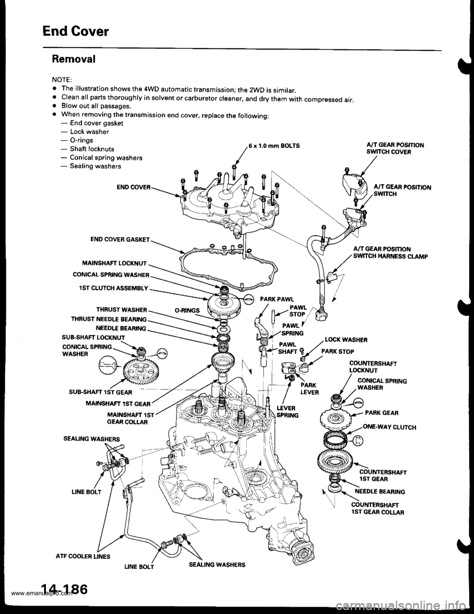
End Cover
Removal
NOTE:
o The illustration shows the 4WD automatic transmission; the 2WD is similar.. cleanall parts thoroughly in solvent or carburetor cleaner, and drythem with compressed air.. Blow out all passages.
. When removing the transmission end cover, replace the following:- End cover gasket- Lock washer- O-rings- Shaft locknuts- Conical spring washers- Sealing washers
END COVER GASKET
MAINSHAFT LOCKNUT
CONICAL SPRING WASHER
6 x 1 .0 rhm EOLTS
PARK PAWL
A/T GEAR POSMONSwlTCH COVER
NEEDI.T BEARING
SUB.SHAFT LOCKNUT
CONICAL SPRINGWASHER
LINE AOLT
ATF COOI.f B LINES
14-186
PAwL 7// Locx wASHER
'sHAFr 9/ ?ARK srop
o-- Ay' couNTERsHAFr
G-€ LocKNUr!€ / ..t,"o, "oo
A/T GEAR POSMONSW|TCH HARNESS CLAMP
CONICAL SPRINGWASHCR
A/T GEAR POSITION
PARK GEAR
Y CLUTCH
lST GEAR
NEEDLE BEARING
1ST CLUTCH ASSEMBLY
THRUST WASHER
THRUST NEEDLE AEARING
O.RINGS
\\
SUB.SHAFT 1ST GEAR
MAINSHAF? 'ST GEAR
MAINSHAFT 1STGEAR COLLAR
SEALING WASHERS
!€'-l
I"EVERSPRING
COUNTERSHAFTlST GEAR COLLAR
PAWL
lt1/ sroe
Y plwl f
L/'SPRING
LOCKNUT
LINE BOLTSEALING WASHERS
www.emanualpro.com
Page 703 of 1395
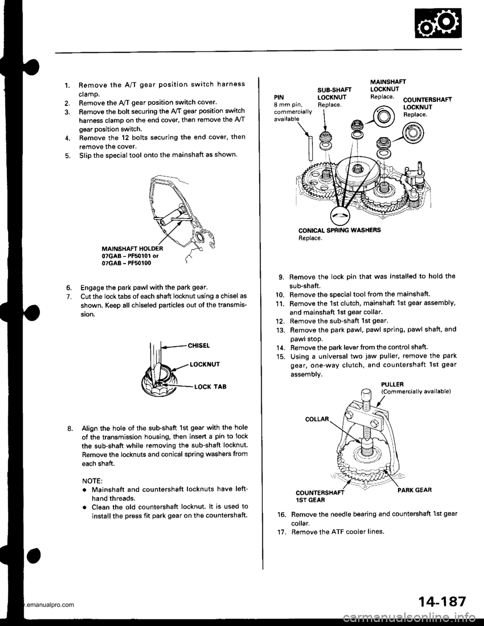
1. Remove the A/T gear position switch harness
cramp.
Remove the y'VT gear position switch cover.
Remove the bolt securing the ly'T gear position switch
harness clamp on the end cover, then remove the A/T
gear position switch.
Remove the 12 bolts securing the end cover. then
remove the cover.
Slip the special tool onto the mainshaft as shown.
6. Engage the park pawl with the park gear.
7. Cut the locktabs of each shaft locknut using a chisel as
shown. Keep all chiseled particles out of the transmis-
ston.
M=tt"
Align the hole of the sub-shaft 1st gear with the hole
of the transmission housing. then insert a pin to lock
the sub-shaft while removing the sub-shaft locknut.
Remove the locknuts and conical spring washers from
each shaft.
NOTE:
Mainshaft and countershaft locknuts have left-
hand threads.
Clean the old countershaft locknut. lt is used to
install the press fit park gear on the countershaft.
MAINSHAFT
PIN8 mm pin,
commercially
SUB-SHAFTLOCKNUTReplace.COUNTERSHAFTLOCKNUTReplace.
CONICAL SPNING WASHERSReplace.
9. Remove the lock pin that was installed to hold the
sub-shaft.
10. Remove the special tool from the mainshaft.
11. Remove the 1st clutch, mainshaft 1st gear assembly,
and mainshaft 1st gear collar.'12. Remove the sub-shaft 1st gear.
13. Remove the park pawl, pawl spring, pawl shaft. and
pawl stoP.
14. Remove the park lever from the control shaft.
15. Using a universal two jaw puller, remove the park
gear, one-way clutch, and countershaft 1st geal
assemblv.
{Commercially available)
1SY GEAR
Remove the needle bearing and countershaft 1st gear
co ar.
Remove the ATF cooler lines,
LOCKNUTReplace.
2\
Irot)
PULLER
11.
14-187
www.emanualpro.com
Page 718 of 1395
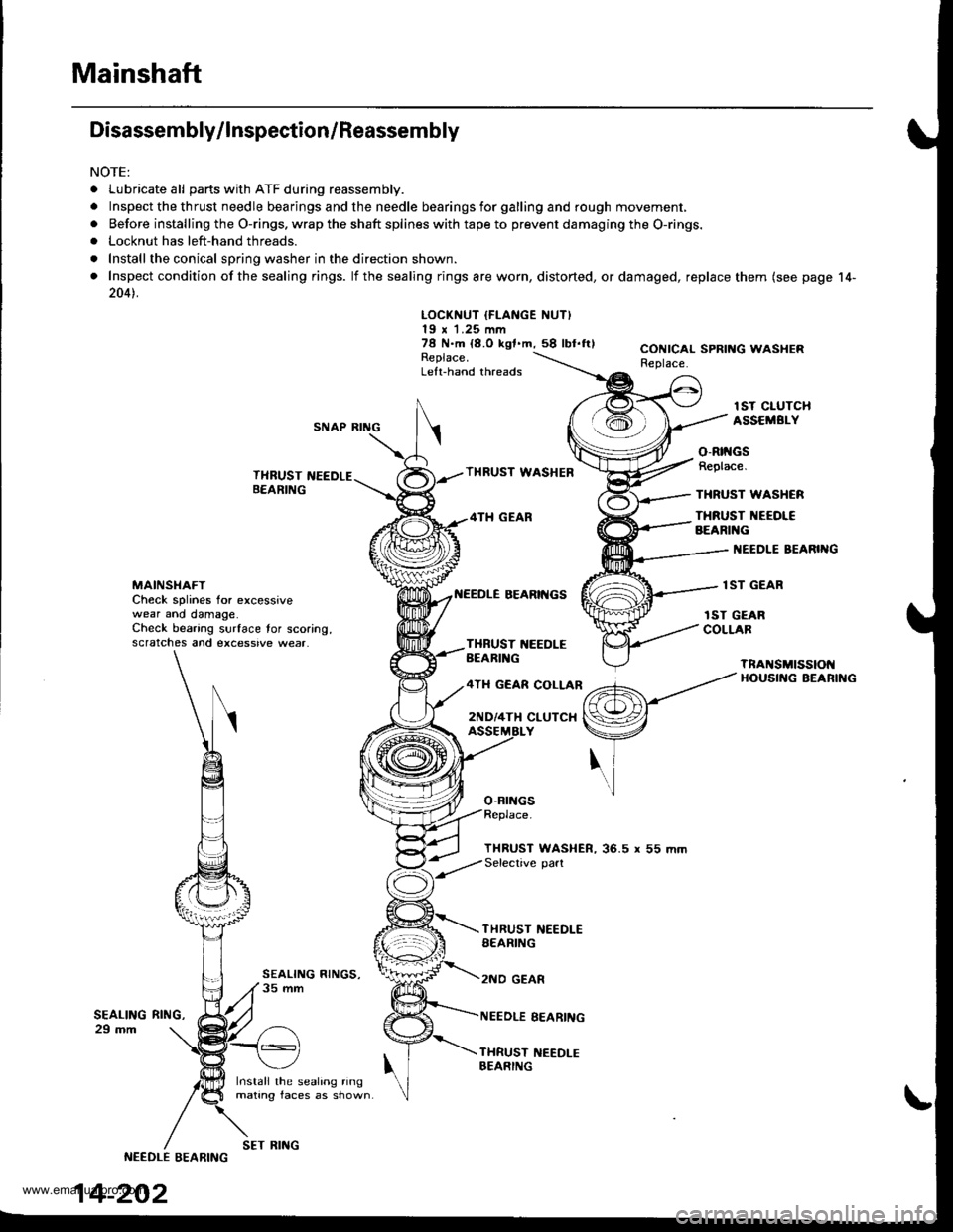
Mainshaft
Disassembly/lnspection/Reassembly
NOTE:
. Lubricate all parts with ATF during reassembly.
.Inspectthethrustneedlebearingsandtheneedlebearingsforgallingandroughmov\
ement,
. Before installing the O-rings. wrap the shaft splines with tape to prevent damaging the O-rings.. Locknut has left-hand threads.
. Install the conical spring washer in the direction shown.
. Inspect condition of the sealing rings. lf the sealing rings are worn, distorted, ordamaged, replace them (see page 14-
2041.
LOCKNUT IFLANGE NUT)19 x 1.25 mm78 N.m {8.O kgf.m,58 lbl.ftlReplace.Left-hand threads
CONICAL SPRING WASHERReplace.
lST CIUTCHASSEMBI.YSNAP RING
THRUST NEEDLEB€ARING
Install the sealing ringmating faces as shown
THRUST WASHEB
4TH GEAR
BEARII{GS
o-Brr{Gs
o-Rtt{GsReplace.
THRUST WASHCR
THRUST NEEOI€BEARIl{G
I{EEDLE BEARIIIG
lST GEARMAINSI{AFTCheck splines for excessivewear ano damage.Check bearing surface tor scoring,scratches and excessive wear.
rST GEARCOLLARTXBUST 1{EEDLEBEARIl{G
4TH GEAR COLLAR
2ND/4TH CLUTCX
TnANSMtSSIOt{HOUSII{G BEARII{G
THRUST WASHER, 36.5 r 55 mmSelective part
SEALING29 mm
THRUST NEEDLESEARING
2NO GEAR
NEEDLE EEARING
THRUST NEEDI-EBEARING
RltrlG,
NEEDLE EEARING
14-202
SET RING
www.emanualpro.com
Page 721 of 1395
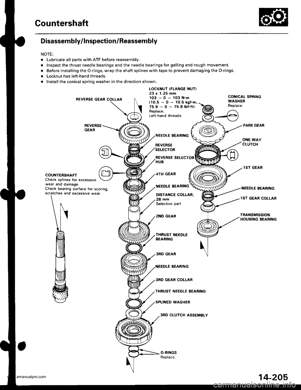
Countershaft
Disassembly/lnspection/Reassembly
NOTE:
. Lubricate all pans with ATF before reassembly.
.Inspectthethrustneedlebearingsandtheneedlebearingsforgallingandroughmov\
ement.
. Before installing the O-rings, wrap the shaft spllnes with tape to prevent damaging the O-rings.
. Locknut has left-hand threads.
. Install the conical spring washer in the direction shown.
R€VERSE GEAR
LOCKNUT IFLANGE NUTI23 x 1.25 mm103-0-103N.mCONICAL SPRINGWASHERReplace.t10.5 - 0 -
75.9 - 0 -
Replace.
10.5 kgl.m,75.9 lbt.lr)
Lelt.hand threads
COUNTERSHAFTCheck splines for excessivewear and damage.
REVERSE SELECTORHUB
4TH GEAR
NEEDLE EEARING
NEEOLE BEARING
REVERSESELECTOR
OISTANCE COLLAR.28 mmSelective part
2NO GEAR
lST GEAR
I{EEDLE BEARINGCheck bearing surface for scoring,scratches and excessive wear.lST GEAR COLLAR
TRANSn SSTONHOUSI G BEARING
3RD GEAR
NEEDLE BEARING
3RD GEAR COLLAR
THRUST NEEOLE BEARING
SPLINED WASHER
3RO CLUTCH ASS€MBLY
14-205
www.emanualpro.com
Page 722 of 1395
Gountershaft
Disassembly/Reassembly
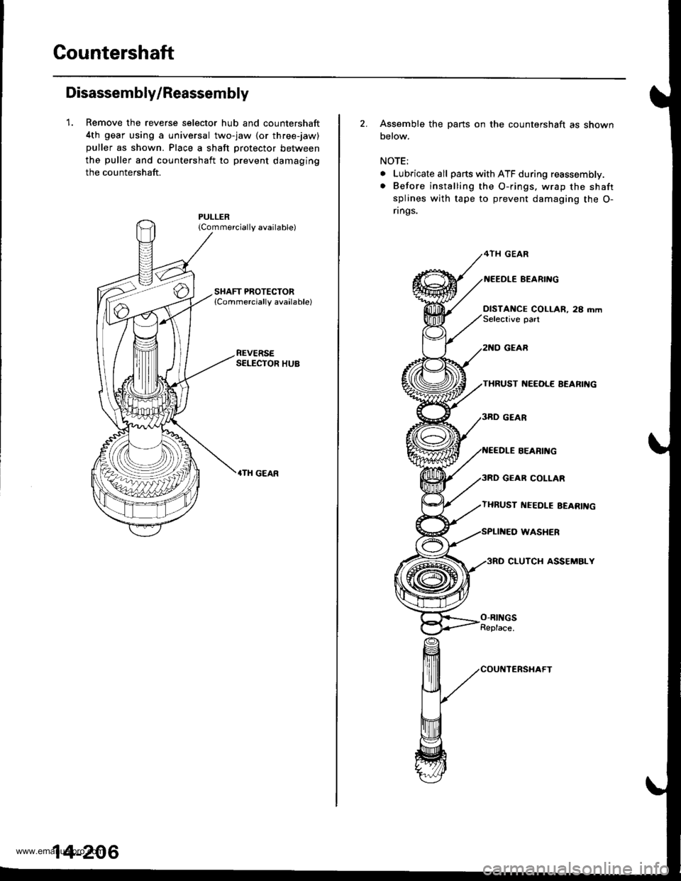
1. Remove the reverse selector hub and countershaft
4th gear using a universal two-jaw lor three-jaw)
puller as shown. Place a shaft protector between
the puller and countershaft to prevent damaging
the countershaft.
{Commercially available)
REVERSESELECTOR HUB
.TH GEAR
14-206
2. Assemble the parts on the countershaft as shown
below.
NOTE;
. Lubricate all parts with ATF during reassembly.
. Before installing the O-rings. wrap the shaft
splines with tape to prevent damaging the O-
rings.
4TH GEAR
BEARI'{G
DISTANCE COLLAR, 28 mmSelective oart
GEAR
THRUST ]{EEOL€ AEARIIIG
GEAR COLLAR
THRUST I{EEDLE EEARII{G
WASHER
3RO CLUTCH ASSEMBLY
SEARII{G
O-RINGSReplace.
www.emanualpro.com
Page 726 of 1395
Sub-shaft
Disassembly/lnspection/Reassembly
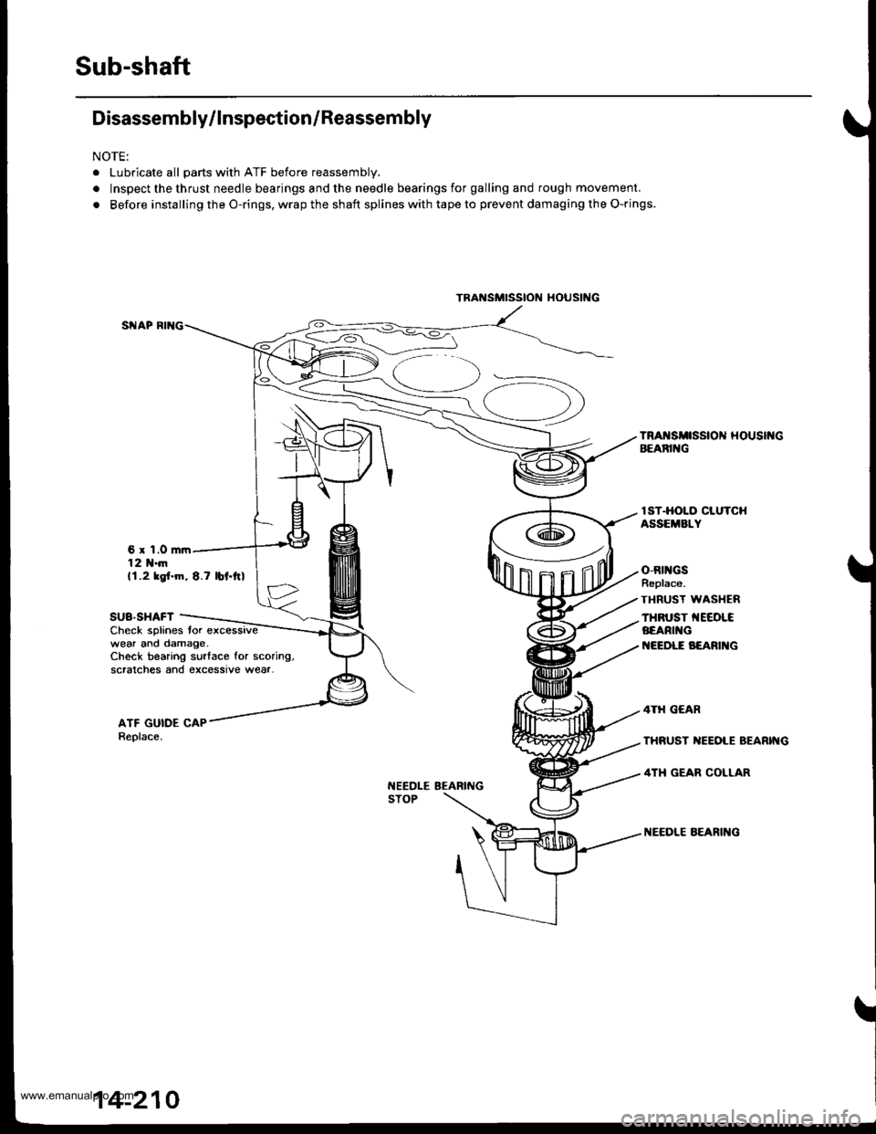
NOTE:
. Lubricate all parts with ATF before reassembly.
. Inspect the thrust needle bearings and the needle bearings for galling and rough movement.
. Before installing the O-rings, wrap the shaft splines with tape to prevent damaging the O-rings.
6 x 1.0 mrr12 1{.mll.2 ksl.m, 8.7 lbt.ftl
SUB.SHAFTCheck splines tor excessivewear ano damage,Check bearing surlace for scoring,scralches and excessive wear-
t{EEDLE BEARINGSTOP
IST.HOLO CLUTCHASSEMBLY
o,Rtl{GSReplace.
TI{RUST WASI{ER
THFUST TEEOLCBEARI G
I{EEDLE B€ARI G
TRAi{SMTSStON tl()UStNG
14-210
www.emanualpro.com
Page 727 of 1395
Disassembly/Reassembly
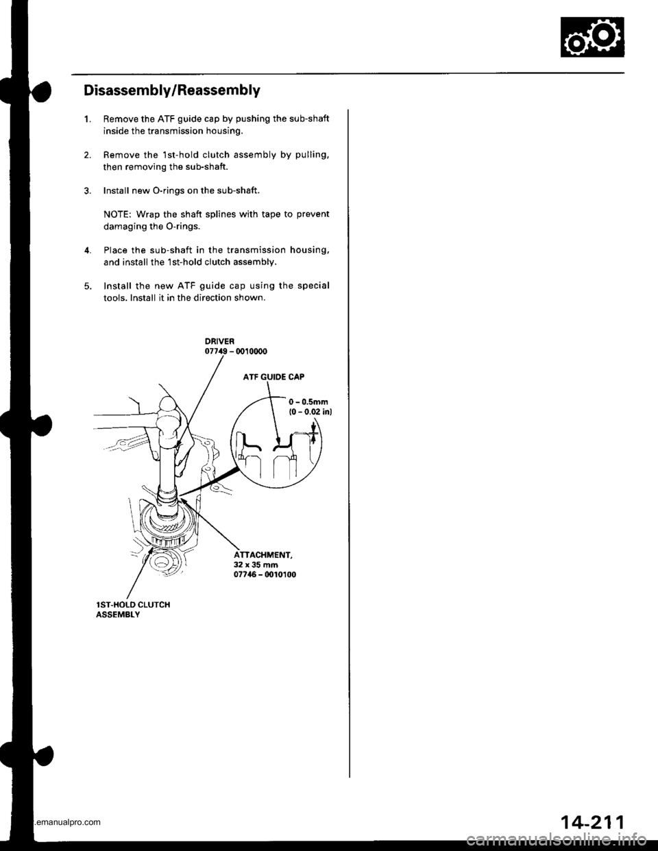
1.Remove the ATF guide cap by pushing the sub-shaft
inside the transmission housing.
Remove the 1st-hold clutch assembly by pulling,
then removing the sub-shaft.
Install new O-rings on the sub-shaft.
NOTE: Wrap the shaft splines with tape to prevent
damaging the O-rings.
Place the sub-shaft in the transmission housing,
and install the'lst-hold clutch assembly,
Install the new ATF guide cap using the special
tools. Install it in the direction shown.
ATTACHMENT,32x35mm07746 - 0010t00
14-211
www.emanualpro.com
Page 771 of 1395
5C.
36.
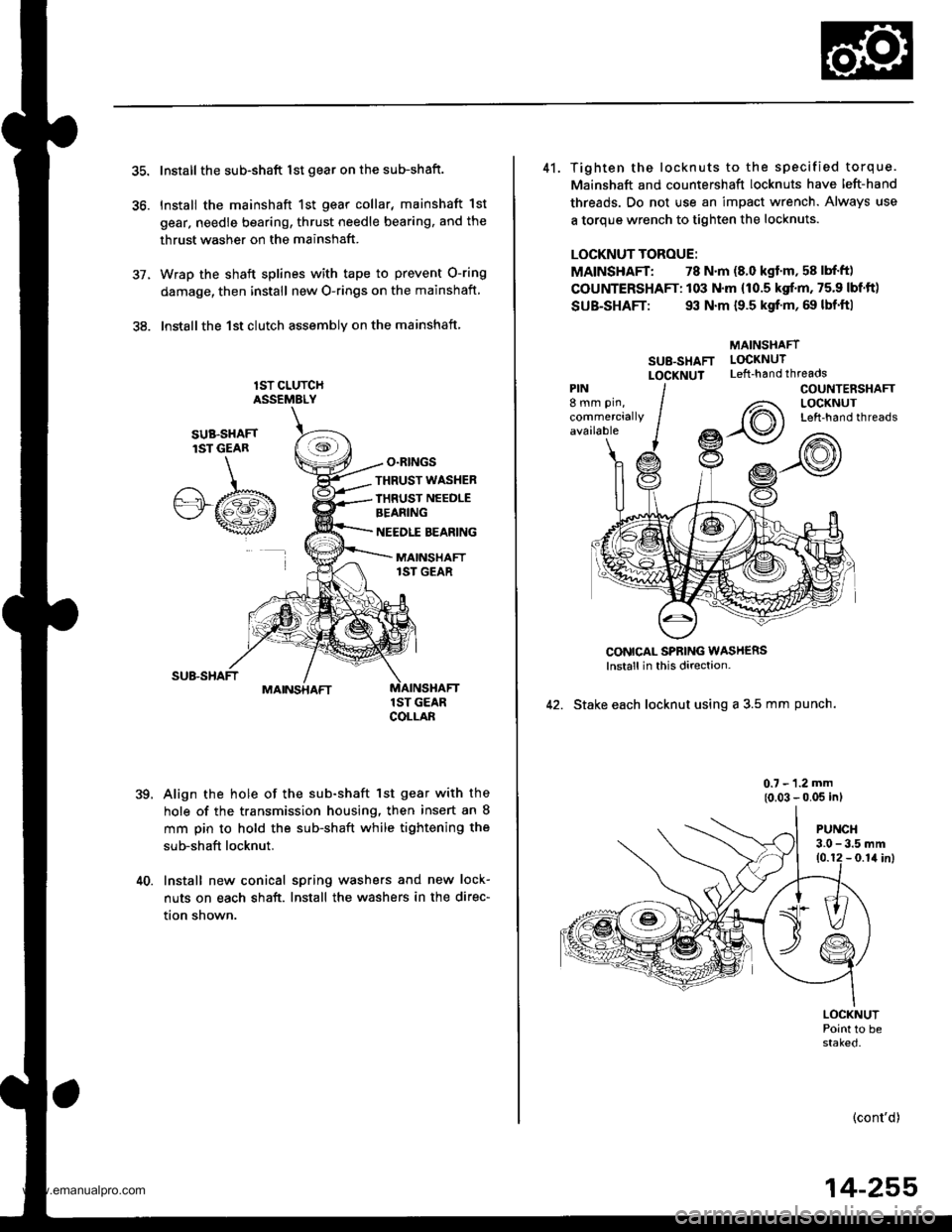
Install the sub-shaft lst gear on the sub-shaft.
Install the mainshaft 1st gear collar, mainshaft 1st
gear, needle bearing, thrust needle bearing, and the
thrust washer on the mainshaft.
Wrap the shaft splines with tape to prevent O-ring
damage, then install new O-rings on the mainshaft
lnstallthe 1st clutch assemblv on the mainshaft
lST CLUTCHASSEMELY
O.RINGS
,te
SUB.SHAFTlST GEAR
.A/.b"'"wt
THRUST WASHER
IHRUST NEEDLEBEANING
NEEDLE BEARING
MAINSHAFT1ST GEAR
MAINSHAFT
39.
1ST GEARCOLLAB
Align the hole of the sub-shaft lst gear with the
hole of the transmission housing, then insert an 8
mm pin to hold the sub-shaft while tightening the
sub-shaft locknut.
40. Install new conical spring washers and new lock-
nuts on each shaft. Install the washers in the direc-
tion shown.
41. Tighten the locknuts to the specified torque.
Mainshaft and countershaft locknuts have left-hand
threads. Do not use an impact wrench. Always use
a torque wrench to tighten the locknuts.
LOCKNUT TOROUE:
MAINSHAFT: 78 N.m (8.0 kgf'm, 58 lbf'ft)
COUNTERSHAFT: 103 N.m (10.5 kgf.m, 75.9 lbf'ft)
SUB-SHAFT: 93 N.m {9.5 kgf'm, 69 lbf'ft|
MAINSHAFT
SU8-SHAFT LOCKNUT
LOCXNUT Left-handthreads
CONICAL SPBING WASH€RSlnstall in this direction-
42. Stake each locknut using a 3.5 mm punch.
0.7 - 1.2 mm
{0.03 - 0.05 inl
PIN8 mm pin,
commerciallyavailable
COUNTENSHAFTLOCKNUTLeft-hand threads
PUNCH3.0 - 3.5 mm10.12 - 0.1il inl
LOCKNUTPoint to bestaked.
(cont'd)
14-255
www.emanualpro.com
Page 773 of 1395
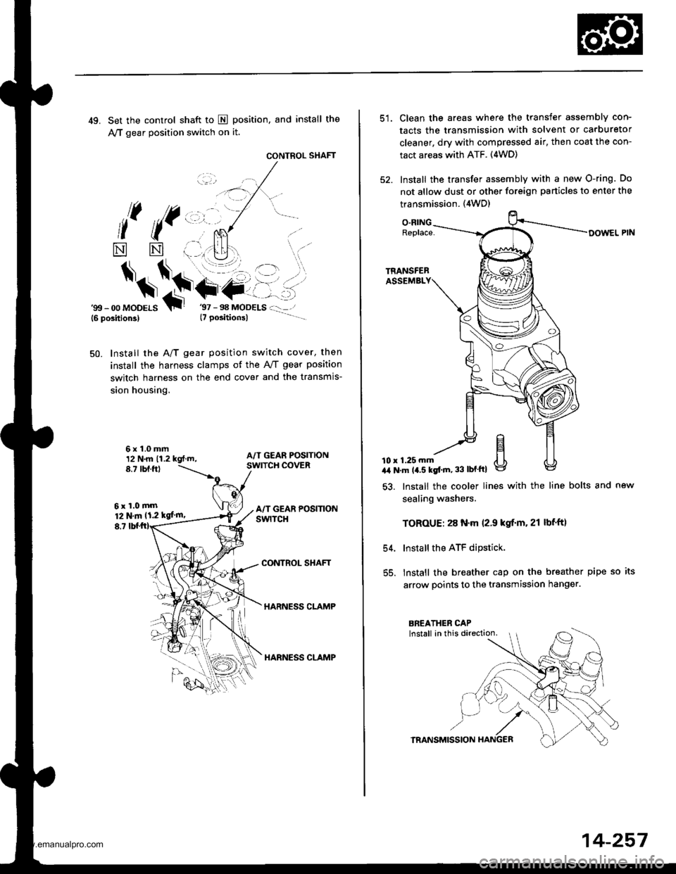
49. Set the control shaft to E position, and install the
A,/T gear position switch on it.
CONTROL SHAFT
l( ((,,, ,.
*
$*\.t+-
NN
6x1.0mm12 N.m 11.2 kgt.m,8.7 tbf.ftl
6xl.0mm12 N.m 11.2 kgf'm,
8,7
'gtt - 00 MoDELS{6 position3}T
Install the A/T gear position switch cover, then
install the harness clamps of the AviT gear position
switch harness on the end cover and the transmis-
sion housing.
50.
CONTROL SHAFT
HARNESS CLAMP
HARNESS CLAMP
Clean the areas where the transfer assembly con-
tacts the transmission with solvent or carburetor
cleaner, dry with compressed air, then coat the con-
tact areas with ATF. (4WD)
Install the transfer assembly with a new O-ring. Do
not allow dust or other foreign particles to enter the
transmission. {4WD)
O.RINGReplace-
10 r 1.25 mma,a N'm 14.5 kgt'm, 33 lbf'ftl
54.
55.
lnstall the cooler lines with the line bolts and new
sealing washers.
TOROUE: 28 N.m 12.9 kgif'm. 21 lbf'ft)
Install the ATF dipstick.
lnstall the breather cap on the breather pipe so its
arrow points to the transmission hanger.
TRANSMISSION
14-257
www.emanualpro.com
Page 776 of 1395
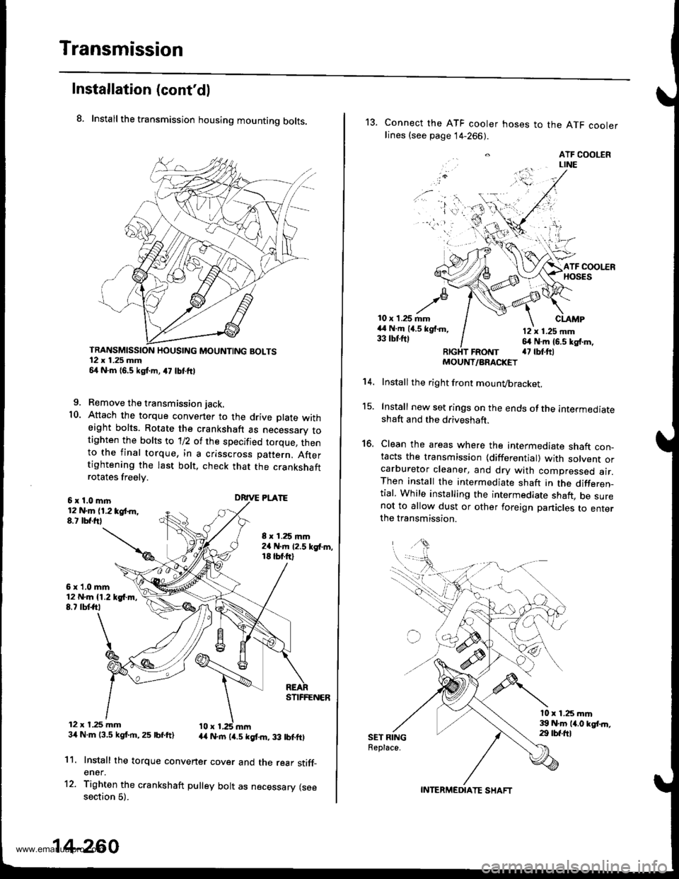
Transmission
Installation (cont'dl
8. Install the transmission housing mounting bolts.
TRANSMISSION HOUSING MOUNTING BOLTS12 x 1.25 mm54 N.m 16,5 kgf.m, a7 lbtftl
9. Remove the transmission jack.
10. Attach the torque convener to the drive plate witheight bolts. Rotate the crankshaft as necessarv totighten the bolts to 'll2 of the specified torque, thento the final torque, in a crisscross pattern. Aftertightening the last bolt. check that the crankshaftrotates freelv.
6x1.0mln12 N.m (1.2 tgt m,8.t lbf.frl
6x1.0mm12 N.m {1.219{.m,8.7 tbtft,
12 x t.25 mm34 N.m 13.5 kgf.rn,25 lbf.ft)
8 x 1.25 mm2a N.m 12.5 kgf'm,18 tbt.ftl
DRIVE PLATE
STIFFENER
44 N.rn (4.5 kgt m, 33 lbtftl
11.
12.
Install the torque convener cover and the rear stiff_ener.
Tighten the crankshaft pulley bolt as necessary (seesection 5).
14-260
13. Connect the ATF cooler hoses to the ATF coolerlines (see page 14-266).
. ATF COOLERLINE
'i 'l'r',:,.) -
10 x 1.25 mm44 N.m (4.5 kgf.m,33 tbtftl
CLAMP
12 x 1.25 mm64 N.m 16.5 kg{.m,a7 tbt.ftlFRotrtT
15.
16.
't 4.
SET RINGReplace.
MOUNT/ARACKET
Install the right front mounvbracket.
Install new set rings on the ends of the intermediateshaft and the driveshaft.
Clean the areas where the intermediate shaft con_tacts the transmission {differential) with solvent orcarburetor cleaner, and dry with compressed air.Then install the intermediate shaft in the differen_tial, While installing the intermediate shaft, be surenot to allow dust or other foreign panicles to enterthe transmission.
l0 x 1.25 mm39 N.m 14.0 kgt.n,29 tbf.ftl
INTERMEDIATE SHAFT
www.emanualpro.com