Ac lines HONDA CR-V 1999 RD1-RD3 / 1.G Service Manual
[x] Cancel search | Manufacturer: HONDA, Model Year: 1999, Model line: CR-V, Model: HONDA CR-V 1999 RD1-RD3 / 1.GPages: 1395, PDF Size: 35.62 MB
Page 780 of 1395
Transmission
Cooler Flushing
@@ To prevent in;ury to face and eyos, atwayswear safety glasses ot a face shield when using thetlansmission flusher.
This procedure should be performed before reinstallingthe transmission.
2.
LCheck equipment for wear and cracks before using.Replace any worn or cracked components.
Using the measuring cup. fill the tank with 21 ounces{approximately 213 lull) ol biodegradable flushingfluid (J35944 - 20). Do not substitute with any otherfluid. Follow the handling procedure on the fluidcontaaner.
Secure the flusher filler cap, and pressurize theflusher with compressed air to 550 - 829 kpa (5.6 _
8.45 kgf/cm,, 80 - 120psi). The air line should beequipped with a water trap to ensure a dry air sys-tem.
Hang the flusher under the vehicle.
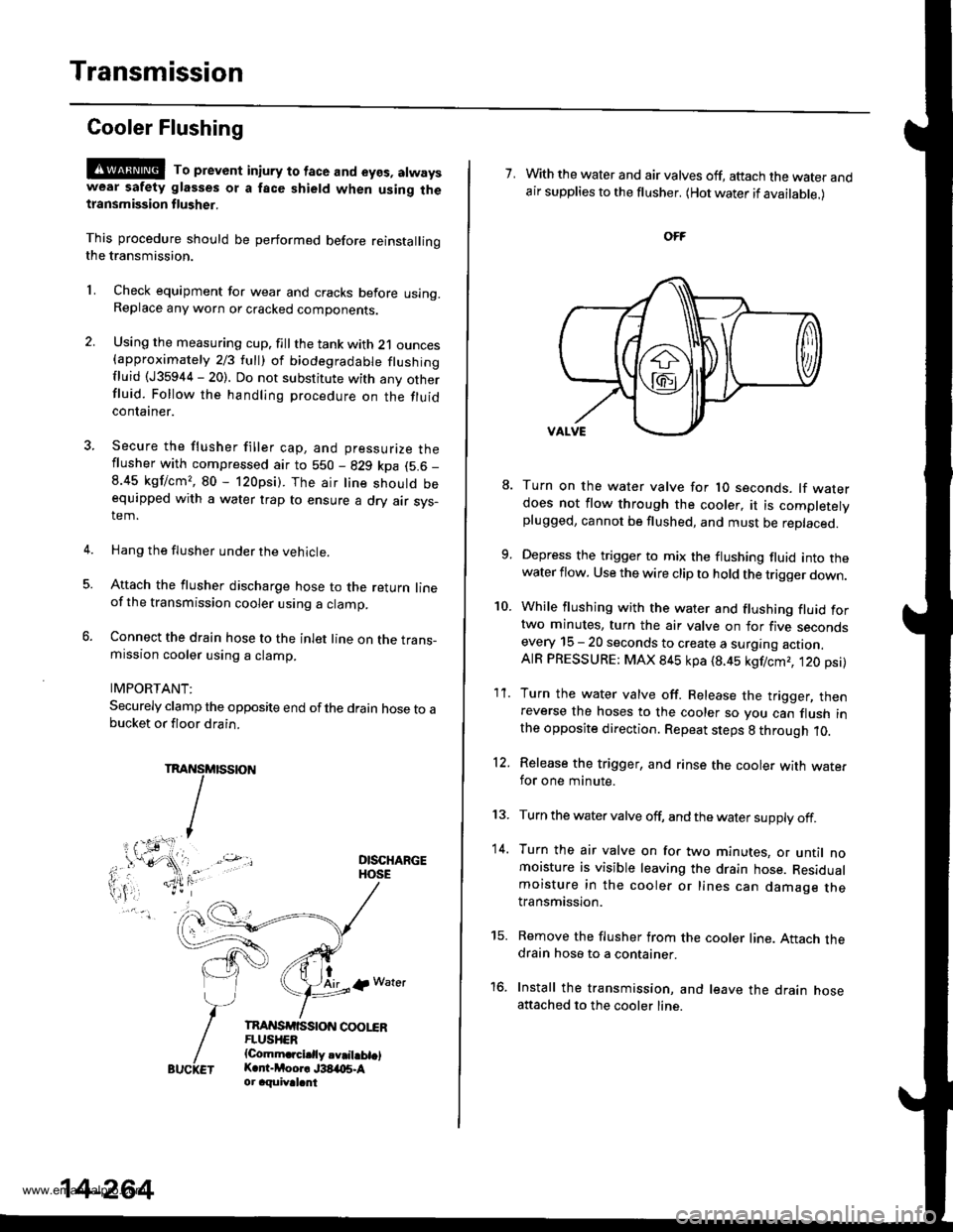
Attach the flusher discharge hose to the return lineof the transmission cooler using a clamp.
Connect the drain hose to the inlet line on the trans-mission cooler using a clamp.
IMPORTANT:
Securely clamp the opposite end ofthe drain hose to abucket or floor drain.
DISCHARGEHOSE
tAirlp Water
TnAI{SrfiSStoN coot"€RFLUSHER{Comm.rcidly.v.il.bt.lK.r -Moor. J38,t{15.Aor aquival.nt
5.
14-264
7. With the water and air valves off, attach the water andair supplies to the flusher. (Hot water if available.)
10.
8.
1'�I.
Turn on the water valve for 1O seconds. lf waterdoes not flow through the cooler, it is completelyplugged, cannot be flushed, and must be replaced.
Depress the trigger to mix the flushing fluid into thewater flow. Use the wire clip to hold the trigger down.
While flushing with the water and flushing fluid fortwo minutes, turn the air valve on for five secondsevery 15 - 20 seconds to create a surging action.AIR PRESSURE: MAX 845 kpa (8.45 kgf/cmr, t20 psi)
Turn the water valve off. Release the trigger, thenreverse the hoses to the cooler so you can flush inthe opposite direction. Repeat steps 8 through 10.
Release the trigger, and rinse the cooler with wate.for one minute.
Turn the water valve off, and the water supply off.
Turn the air valve on for two minutes, or until nomoisture is visible leaving the drain hose. Residualmoisture in the cooler or lines can damage thetransmission.
Remove the flusher from the cooler line. Attach thedrain hose to a container.
Install the transmission, and leave the drain hoseattached to the cooler line.
12.
13.
14.
to.
www.emanualpro.com
Page 782 of 1395
ATF Cooler Hoses
Gonnection
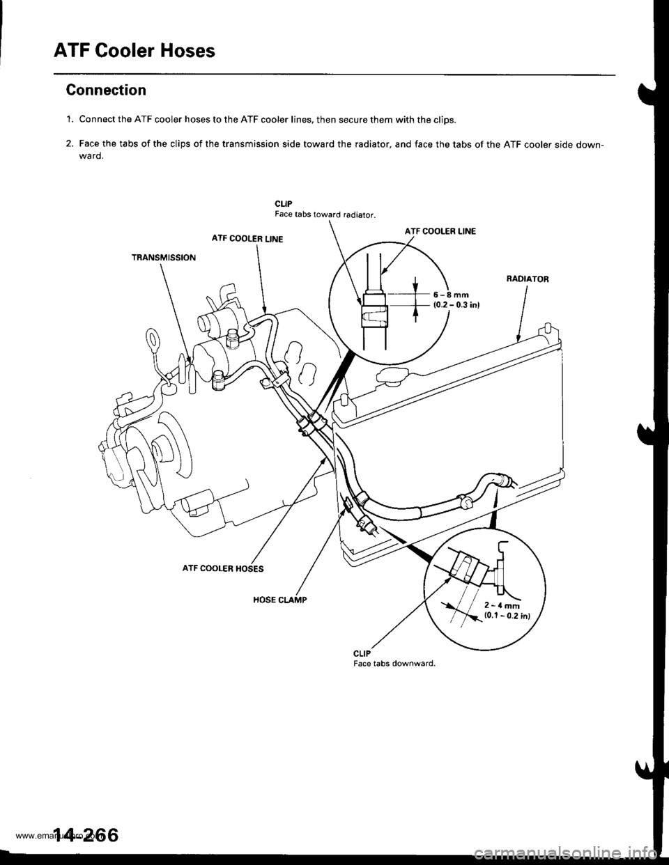
'1. Connect the ATF cooler hoses to the ATF cooler lines. then secure them with the cliDs.
2. Face the tabs of the clips of the transmission side toward the radiator, and face the tabs of the ATF cooler side down-wa rd.
CLIPFace tabs toward radiator.
ATF COOLER LINEATF COOLER LINE
TRANSMISSION
6-8mm(0.2 - 0.3 inl
ATF COOLER
HOSE CLAMP
CLIPFace tabs downward.
2-rlmm10.1 - 0.2 inl
14-266
www.emanualpro.com
Page 818 of 1395
DriveshaftsFront Driveshafts
Inspection
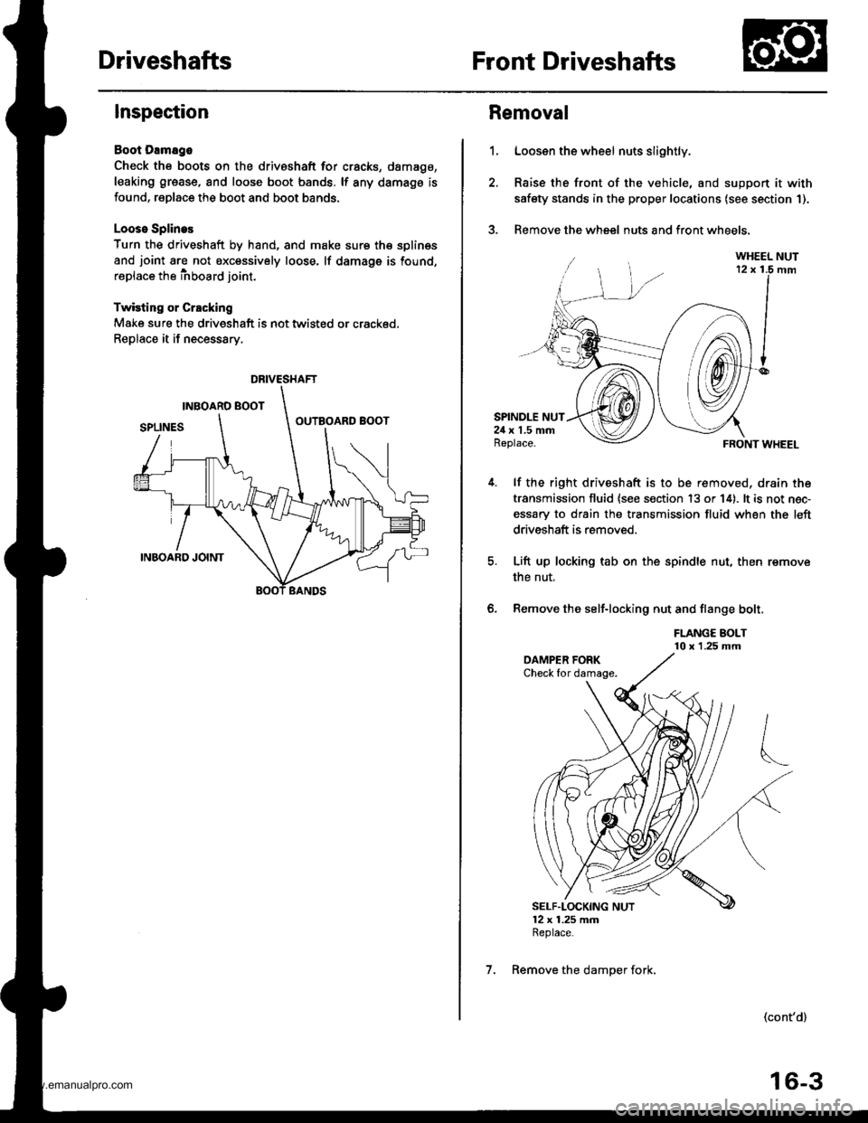
Boot Damago
Check the boots on the driveshaft for cracks, damago,
leaking grease, and loose boot bands. lf any damags is
found, replace the boot and boot bands.
Looso Splines
Turn the driveshaft by hand, and make sure th€ splin€s
and joint are not excessively loose. lf damage is found,
replace the inboard joint.
Twisting or Crscking
Make sure the driveshaft is not twisted or crackod.
Replace it if necessary.
DRIVESHAFT
1.
Removal
Loosen the wheel nuts slightly.
Raise the front of the vehicle, and suppon it with
safety stands in the proper locations (see section 1).
Remove the wheel nuts and front wheels.?
SPINDLE NUT24 x 1.5 mmReplace.
lf the right driveshaft is to be removed, drain the
transmission fluid {see s€ction 13 or 14). lt is not nec-
essary to drain the transmission fluid when the left
driveshaft is removed.
Lift up locking tab on the spindle nut, then remove
the nut,
Remove the self-locking nut and flange bolt,
FLANGE BOLT10 x 1.25 mm
FRONT WHEEL
(cont'd)
6.
SELF"LOCKING NUT12 x 1.25 mmReplace.
7. Remove the damper fork,
16-3
www.emanualpro.com
Page 821 of 1395
Front Driveshafts
Disassembly (cont'd)
Double Loop
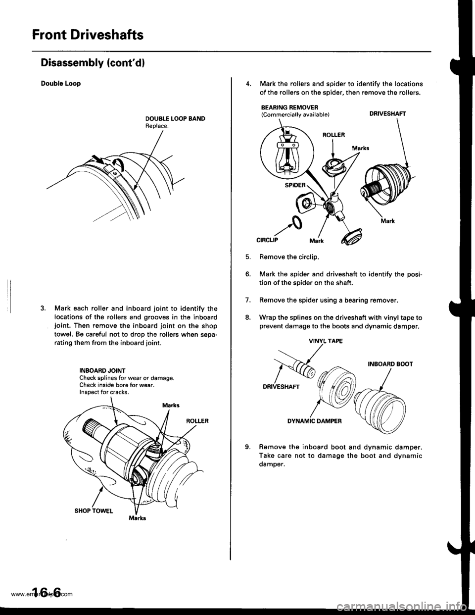
Mark each roller and inboard joint to identify the
locations of the rollers and grooves in the inboardjoint. Thon remove the inboard ioint on the shop
towel. Be careful not to drop the rollers when sepa-
rating them from the inboard joint.
INBOARD JOINTCheck splines for wear or damage.Check inside bore for wear.Inspect for cracks.
16-6
4, Mark the rollers and spider to identify the locstions
of the rollers on the sDider, then remove the rollers.
BEARING REMOVER(Commercially available) DRIVESHAFT
Remove the circlip,
Mark the spider and driveshaft to identify the posi-
tion ofthe spider on the shaft.
Remove the spider using a bearing remover,
Wrap the splines on the driveshaft with vinyl tape to
prevent damage to the boots and dynsmic damper,
7.
q
INBOARD BOOT
DRIVESHAFT
DYNAMIC DAMPER
Rsmove the inboard boot and dvnamic
Take care not to damage the boot and
damDer.
damper.
dynamic
DRIVESHAFT
Mark
www.emanualpro.com
Page 823 of 1395
![HONDA CR-V 1999 RD1-RD3 / 1.G Service Manual
Front Driveshafts
parts with solvent.
o *4@] :Thoroughly pack the inboard and outboard joints and both joint boots with the joint grease included in the
new driveshaft set.. The98 Canada model andal HONDA CR-V 1999 RD1-RD3 / 1.G Service Manual
Front Driveshafts
parts with solvent.
o *4@] :Thoroughly pack the inboard and outboard joints and both joint boots with the joint grease included in the
new driveshaft set.. The98 Canada model andal](/img/13/5778/w960_5778-822.png)
Front Driveshafts
parts with solvent.
o *4@] :Thoroughly pack the inboard and outboard joints and both joint boots with the joint grease included in the
new driveshaft set.. The'98 Canada model andall '99 - 00 models use a TPE (Thermoplastic Polyester E lastomer) outboard joint boot.
Use the ear clamp type boot band in the outboard boot set.
Grease quantity:
Inboard Joint: All models 120 - 130 g (i1.2 - 4.6 oz)
Left inboard joint splines (Al: 0.5 - 1.0 g (0.018 - 0.035 oz)
Outboard Joint: '97 model and'98 USA model 130 - 140 g (4.6 -,1.9 oz)'98 Canada model and all '99 - 0O models 140 - 150 g 14.9 - 5.3 oz)
Reassembly
Note these items during reassembly
. Clean the disassembled parts with solvent, anddry them thoroughly with compressed air. Do not wash the rubber
INBOARO JOINT
SPIOERINBOARD BOOT
SET RINGReplace.
LEFT INBOAROJOINT
SPLINES: (Al-6rPack cavity with grease.
wtn grease.
BANDS
DYNAMIC DAMPER
STOP RINGReplace.
OUTBOARD BOOT
EAR CLAMPReplace.
ITPE)*I
-611
-/ Pack cavity with grease.
DOUELEReplace.BAND+'BAND*1
__G1Pack cavitywrtn grease.
OUTBOARD BOOT*'(RUBBERI
-GrjPack cavity*l: '98 Canada models, all '99-00models
*2: '97 - 98 models (except'98 Canada model)
16-8
wtrn grease.
www.emanualpro.com
Page 824 of 1395
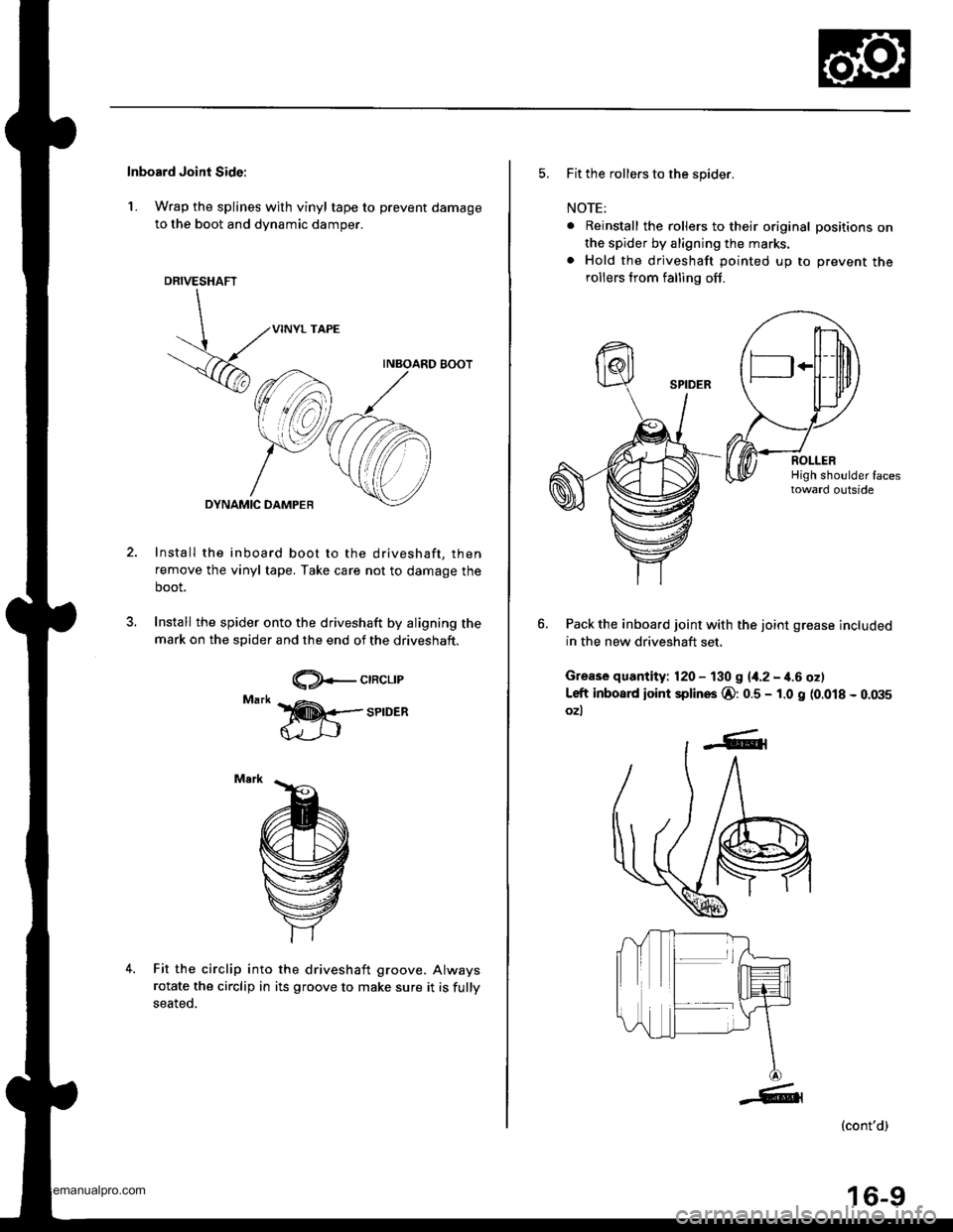
Inboard Joint Side:
1. Wrap the splines with vinyl tape to prevent damage
to the boot and dynamic damper.
DRIVESHAFT
,..',NYL rAPE
V6
uu.oa.Dsoo.�
,",^_Y,C@
Install the inboard boot to the driveshaft, then
remove the vinyl tape. Take care not to damage the
boot.
Install the spider onto the driveshaft by aligning the
mark on the spider and the end of the driveshaft.
@+-crncr-rr
4.Fit the circlip into
rotate the circlip in
seated.
the driveshaft groove. Always
its groove to make sure it is fully
5. Fit the rollers to the spider.
NOTE:
. Reinstall the rollers to their original positions onthe spider by aligning the marks.
. Hold the driveshaft pointed up to prevent therollers from falling off.
Pack the inboard joint with the joint grease included
in the new driveshaft set,
Grease quantity: 120 - 130 g {4.2 - 4.6 oz)
Left inboad ioint splines @:0.5 - 1.0 g (0.018 - 0.m5
ozl
(cont'd)
F
16-9
www.emanualpro.com
Page 827 of 1395
Front Driveshafts
Reassembly (cont'd)
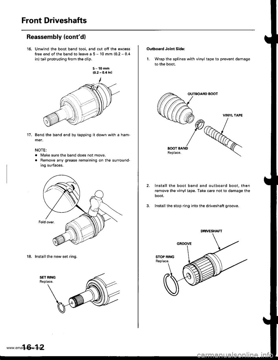
16. Unwind the boot band tool. and cut off the excess
free end of the band to leave a 5 - 10 mm (0.2 - 0.4
in) tail protruding from the clip.
5- 10 mm
10.2 - 0.4 in,
Bend the band end by tapping it down with a ham-
mer,
NOTE;
. Make sure the band does not move,
. Remove any grease remaining on the surround-
ing surfaces.
18, Install the new set ring.
17.
16-12
Outbosrd Joint Sids:
1. Wrap the splines with vinyl tape to prevent damage
to the boot.
OUTBOARD BOOT
2, Install the boot band and outboard boot, then
remove the vinyl tape. Take care not to damage the
boot.
3. Install the stop ring into the driveshaft groove.
VINYL TAPE
DRIVESHAFT
www.emanualpro.com
Page 832 of 1395
Front Driveshafts
lnstallation
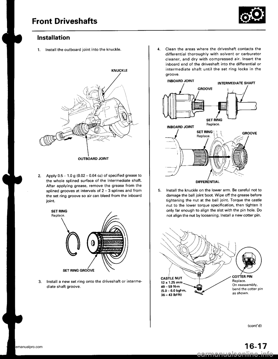
1. Install the outboard ioint into the knuckle.
KNUCKLE
OUTBOARD JOINT
Apply 0.5 - 1.0 g (0,02 - 0.04 oz) of specified grease to
the whole sDlined surface of the intermediate shaft.
After applying grease. remove the grease from the
splined grooves at intervals of 2 - 3 splines and from
the set ring groove so air can bleed from the inboard
ioint.
SET RINGReplace.
SET RING
Install a new set ring onto the driveshaft or interme-
diate shaft groove.
4. Clean the areas where the driveshaft contacts the
differential thoroughly with solvent or carburetor
cleaner, and dry with compressed air. Insert the
inboard end of the driveshaft into the differential or
intermediate shaft until the set ring locks in the
groove.
INBOARD JOINT
INBOARD JOINT
lnstall the knuckle on the lower arm. Be careful not to
damage the ball joint boot. Wipe off the grease before
tightening the nut at the ball joint. Torque the castle
nut to the lower torque specification. then tighten it
only far enough to align the slot with the pin hole. Do
not align the nut by loosening. lnstall a new cotter pin.
5.
CASTLE NUT12 x 1 .25 mm49-59Nm(5.0 - 6.0 kgl'm,36 - 4:l lbl.ft)
COTTER PINReplace.On reassembly,bend the cotter pin
(cont'd)
16-17
Replace.
www.emanualpro.com
Page 838 of 1395
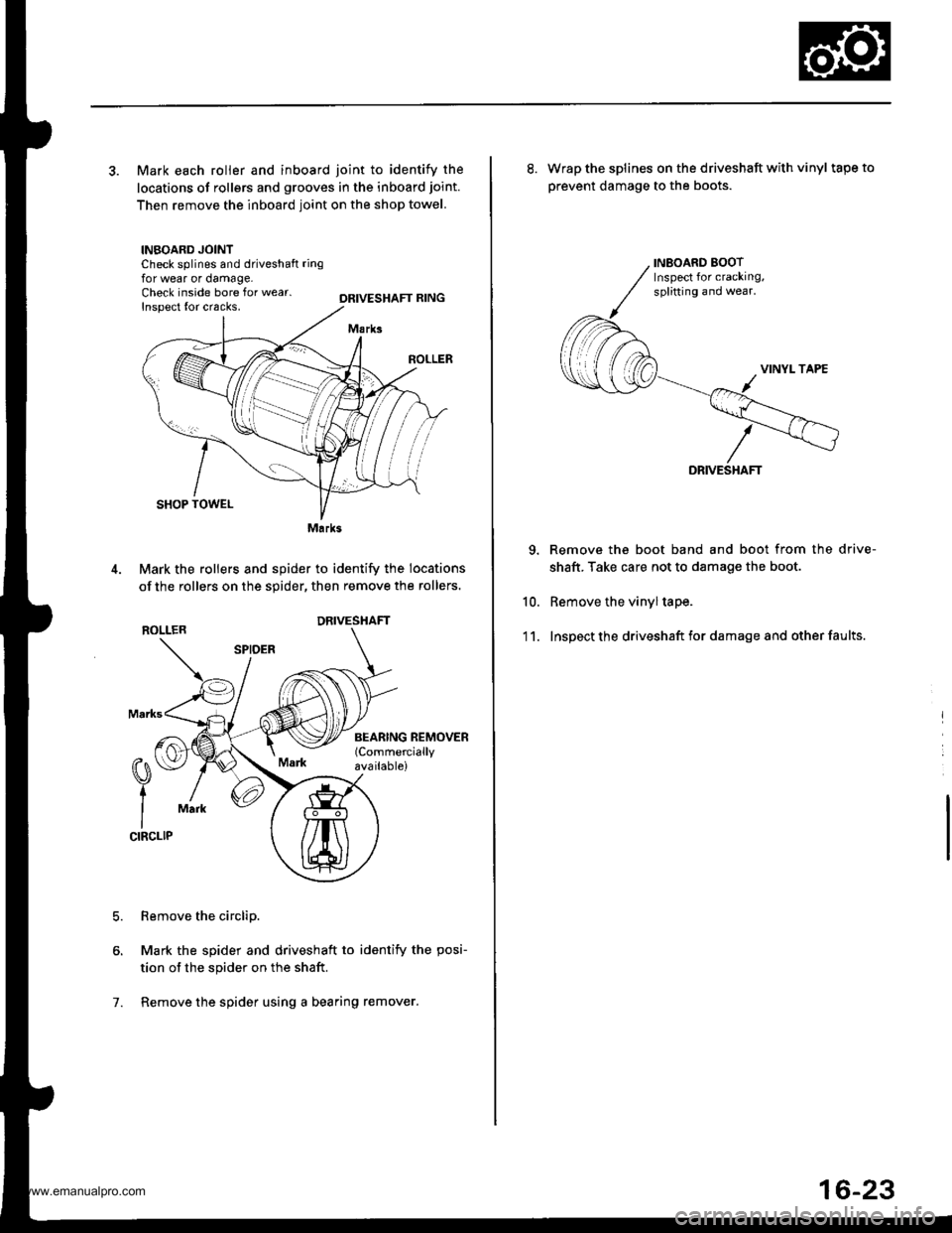
3. Mark each roller and inboard joint to identify the
locations of rollers and grooves in the inboard joint.
Then remove the inboard joint on the shop towel.
INBOARD JOINTCheck splines and driveshaft ringfor wear or damage,Check inside bore for wear.Inspect {or cracks,DRIVESHAFT RING
M.rks
SHOP TOWEL
Mark the rollers and spider to identify the locations
of the rollers on the sgider, then remove the rollers,
ROLLER
Remove the circlip.
Mark the spider and driveshaft to identify the posi-
tion of the spider on the shaft.
Remove the spider using a bearing remover.
0\
t
ICIRCLIP
Mark
7.
Marks
DRIVESHAFT
INEOARD BOOTInspect for cracking,splitting and wear.
10.
'1 1.
8. Wrap the splines on the driveshaft with vinyl tapeto
prevent damage to the boots.
DRIVE
Remove the boot band and boot from the drive-
shaft. Take care not to damage the boot.
Remove the vinyl tape.
Inspect the driveshaft for damage and other faults.
16-23
www.emanualpro.com
Page 840 of 1395
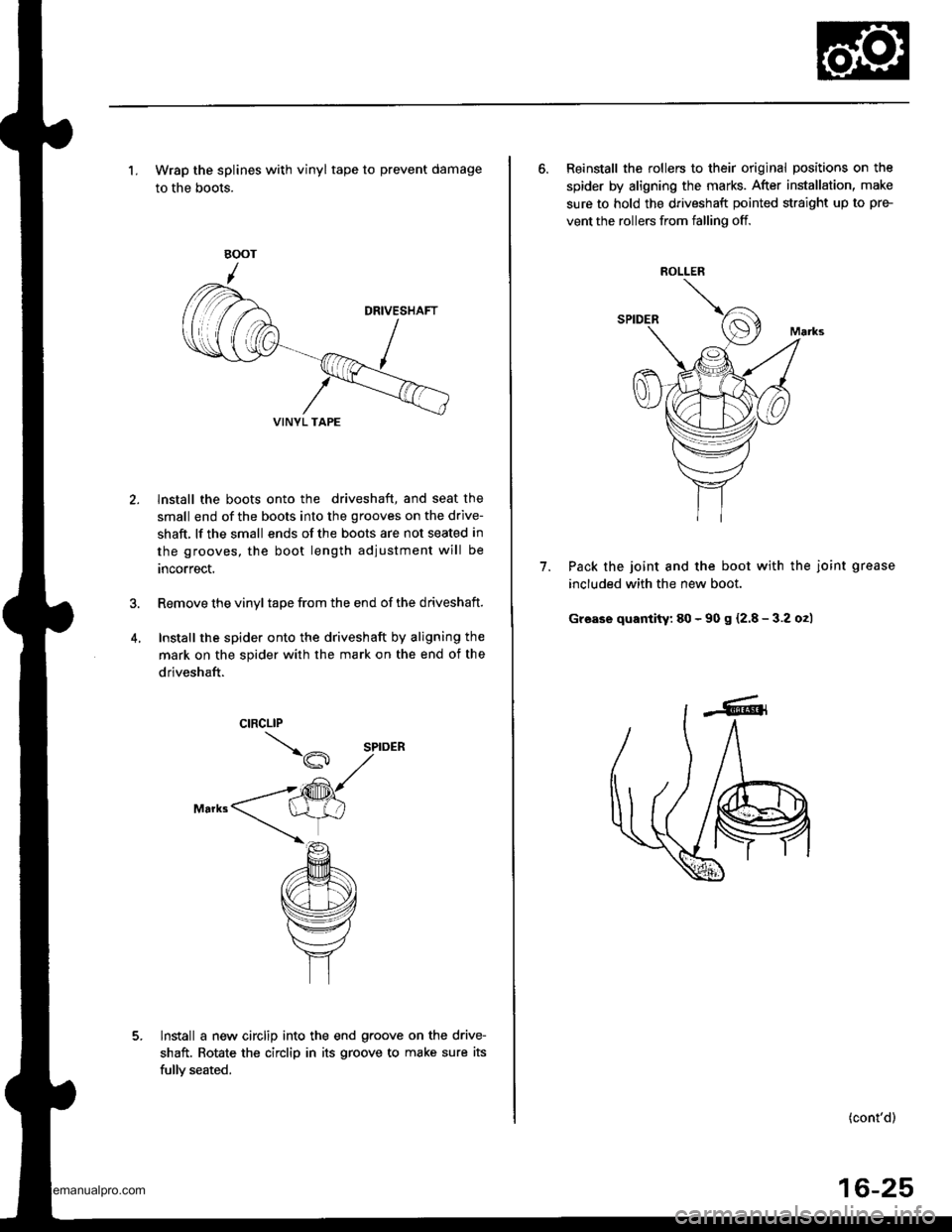
'1. Wrap the splines with vinyl tape to prevent damage
to the boots.
lnstall the boots onto the driveshaft, and seat the
small end of the boots into the grooves on the drive-
shaft, lf the small ends of the boots are not seated in
the grooves, the boot length adiustment will be
rncorrect.
Remove the vinyl tape from the end of the driveshaft.
Install the spider onto the driveshaft by aligning the
mark on the spider with the mark on the end of the
driveshaft.
lnstall a new circlip into the end g.oove on the drive-
shaft. Rotate the circlip in its groove to make sure its
fullv seated.
VINYL TAPE
6. Reinstall the rollers to their original positions on the
spider by aligning the marks. After installation, make
sure to hold the driveshaft pointed straight up to pre-
vent the rollers from falling off.
Pack the joint and the boot with the joint grease
included with the new boot.
Grease quantity: 80 - 90 s {2.8 - 3.2 o2)
7.
ROLLER
(cont'd)
16-25
www.emanualpro.com