34 shift valve HONDA CR-V 1999 RD1-RD3 / 1.G Service Manual
[x] Cancel search | Manufacturer: HONDA, Model Year: 1999, Model line: CR-V, Model: HONDA CR-V 1999 RD1-RD3 / 1.GPages: 1395, PDF Size: 35.62 MB
Page 601 of 1395
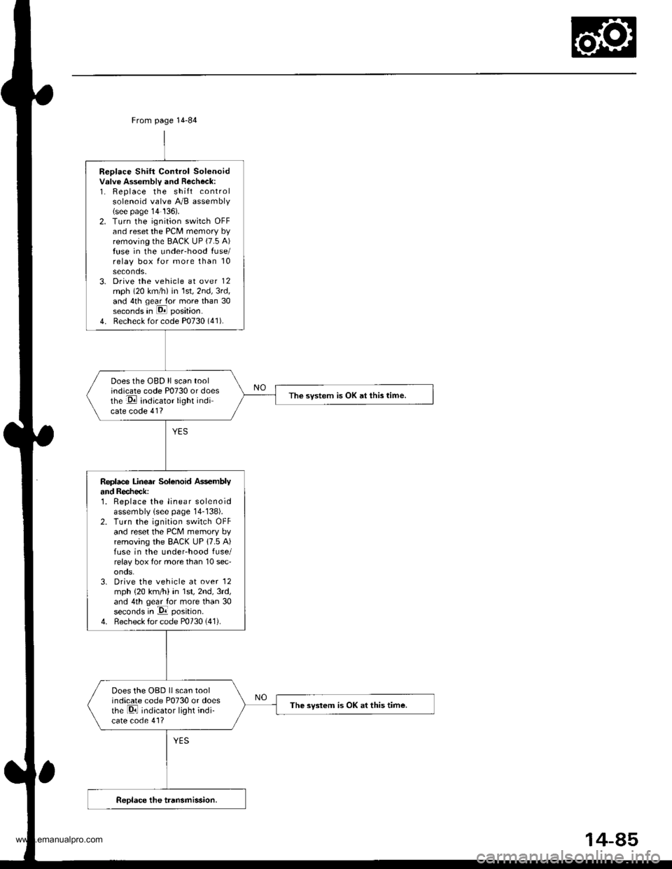
Replace Shift Control Solenoidvslve Assembly and Recheck:1. Replace the shift controlsolenoid valve A/B assembly(see page'14 136).2. Turn the ignition switch OFFand reset the PCM memory byremoving the BACK UP (7.5 A)fuse in the under-hood fuse/relay box for more than 10seconds.3. Drive the vehicle at over 12mph (20 km/h) in 1st,2nd,3rd,and 4th qear for more than 30seconds in E position.
4. Recheck for code P0730 (41).
Does the OBD ll scan toolindicate code P0730 or doesthe E indicator light indicate code 41?
The svstem is OK at this time.
Replace Linea. Solenoid Ass€mblyand Recheck:1. Replace the linear solenoidassembly lsee page 14-138).2. Turn the ignition switch OFFand reset the PcM memory byremoving the BACK UP 17.5 A)fuse in the underhood fuse/relay box tor more than 10 sec'onos.3. Drive the vehicle at over '12
mph {20 km/h) in 1st,2nd,3rd,and 4th geal for more than 30seconds in -Da position.
4. Recheck for code P0730 (41).
Does the OBD llscan toolindicate code P0730 or doesthe Di indicator light indi-cate code 41?
The syslem is OK at this time.
From page 14-84
14-85
www.emanualpro.com
Page 622 of 1395
Electrical Troubleshooting ('98 - 00 Models)
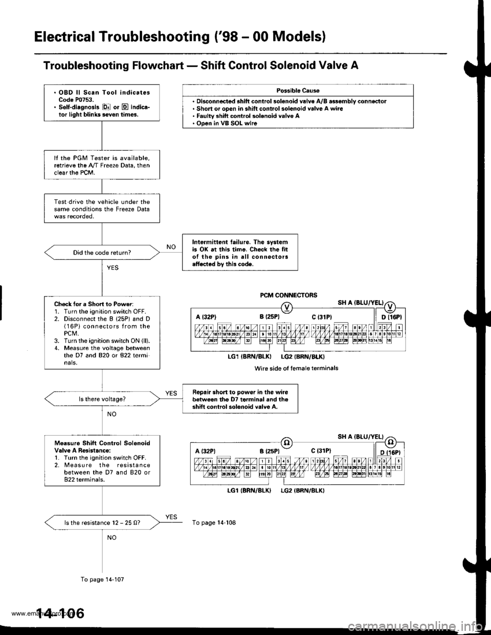
Troubleshooting Flowchart - Shift Control Solenoid Valve A
Po$ible Caus€
'. Short or open in shift control solenoid valve A wire. Faulty 3hift control 3olenoid valvo A. Ooen in VB SOL wire
LGl
To page 14-108
(BRN/BLKILG2 (BRN/BLKI
A t32P) 8 {2sPl Ct3lPt ll Dll6Pt
LG1IBRN/BLKI LG2IBRN/BLK}
Wi16 side of femaleterminals
A (:l2Pl a t25Pl - c {31P}
. OBD ll Scan Tool indicatesCode P0753.. Self-diagnosis El or E indica-tor light blihk5 ievon times.
It the PGM Tester is available,retrieve the A"/T Freeze Data, thenclear th€ PCM.
Test drive the vehicle under thesame conditions the Freeze Data
Intermittent tailure. The systemb OX at this timo. Check the fito{ the pins in all connectora.ttected by this code.
Did the code return?
Ch6ck for a Short 1o Power:1. Turn the ignition switch OFF.2. Disconnect the B (25P) and D(16Pi connectors from thePCM,3. Turn the ignition switch ON (ll).
4. Measure the voltage betweenthe D7 and 820 or 822 terminals.
Repair short to power in the wirebetwoen tho D7 terminal and theshift control solenoid valve A.
Moasure Shift Control SolenoidValv6 A Resistanco:1. Turn the ignition switch OFF.2. [reasu re the resistancebetween the D7 and 820 or822 terminals.
ls the resistance l2 - 25 0?
To page 14-107
14-106
www.emanualpro.com
Page 623 of 1395
![HONDA CR-V 1999 RD1-RD3 / 1.G Service Manual
A l32Pl
From page 14-106PCM CONNECTORS
B (25P1 C (31
LGl IERN/BLKILG2 {BRN/BLK)
Wire side of female terminals
LGl IBRN/BLK}LG2 (BRN/BLK}
SHIFT CONTROI SOLENOIDVALVE A/B ASSEMBLY CONNECTOR
IiiE-]
"*ot HONDA CR-V 1999 RD1-RD3 / 1.G Service Manual
A l32Pl
From page 14-106PCM CONNECTORS
B (25P1 C (31
LGl IERN/BLKILG2 {BRN/BLK)
Wire side of female terminals
LGl IBRN/BLK}LG2 (BRN/BLK}
SHIFT CONTROI SOLENOIDVALVE A/B ASSEMBLY CONNECTOR
IiiE-]
"*ot](/img/13/5778/w960_5778-622.png)
A l32Pl
From page 14-106PCM CONNECTORS
B (25P1 C (31
LGl IERN/BLKILG2 {BRN/BLK)
Wire side of female terminals
LGl IBRN/BLK}LG2 (BRN/BLK}
SHIFT CONTROI SOLENOIDVALVE A/B ASSEMBLY CONNECTOR
IiiE-]
"*otrau/"aalF
I
Termanal side of male terminals
(cont'd)
14-107
c (31P)D {16P)
Check for continuity between the820 terminal and body ground.
and between the 822 terminaland body ground.
Ropair open in the wir.s betweonthe 820 and 822 terminal3 andground (G1011.
Check Shilt Control SolenoidValve A for . Short Circuit:1. Disconnect the 2P connectorfrom the shift control solenoidvalve !y'B assembly.2. Check tor continuity betweenthe D7 and B2O ot 822 tetmi-nals.
Repair short to ground in the wirebe{we€n the D7 terminal and the3hift control solonoid valvo A.ls there continuity?
Measure Shift Control SolenoidValve A Resistance at iheSolenoid Connector:Measure the resistance betweenthe No. I terminal of the shiftcontrol solenoid va lve A/Bassembly connector and bodygrou nd,
Replace the shrft control solenoidvalve A/B assembly.ls the resistance 12 25 Q?
Check for op.n in the wirebetwoon tho D7 terminal and theshift control solenoid valve A.
www.emanualpro.com
Page 624 of 1395
Electrical Troubleshooting ('98 - 00 Models)
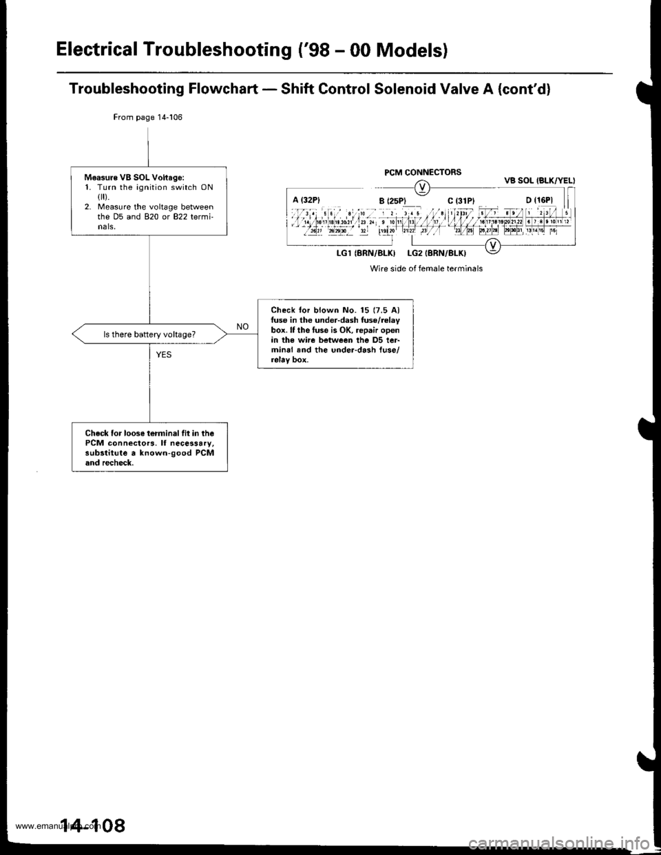
Troubleshooting Flowchart - Shift Control Solenoid Valve A (cont'd)
From page 14-106
Wire side of female terminals
Moasure VB SOL Voftago:1. Turn the ignition switch ONflr).2. Measure the voltage betweenthe D5 and 820 or 822 termi-nals,
Check lor blown No. 15 (7.5 Alfuse in the under-dash fuse/relaybox. lf the tuse is OK, repair openin the wi.e between the D5 ter-minal and the under-dash fuse/relay box.
ls there battery vohage?
Check for loose terminalfit in thePCM connectors. lf necessary,subltitute a known-good PCMand recheck.
VB SOL IBLK/YEL)
14-108
www.emanualpro.com
Page 625 of 1395
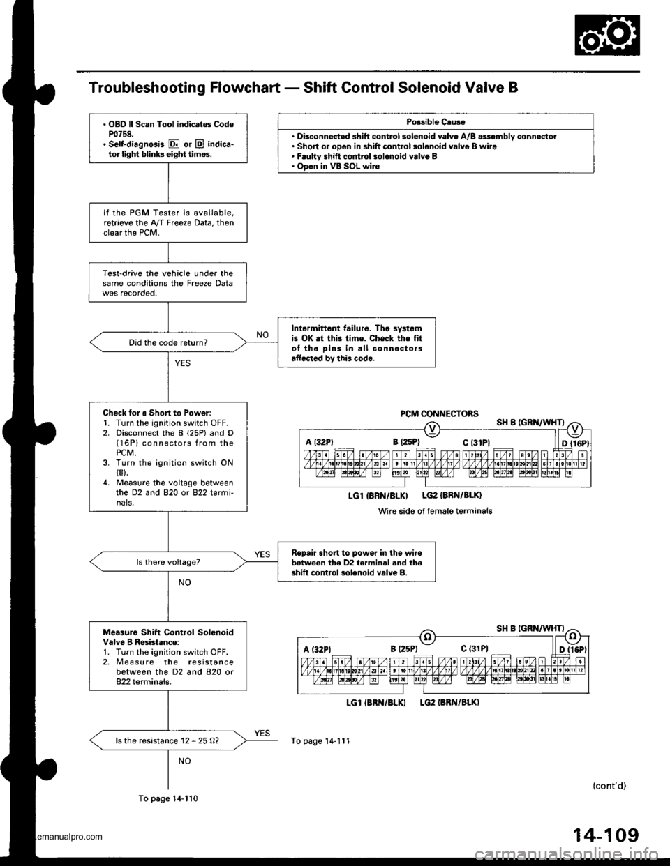
Troubleshooting Flowchart - Shift Control Solenoid Valve B
Po3sible C.us€
.Dt. Short or oDen in shift control solenoid valve B wira' F.ulW shitt cont.ol solonoid valvc B. Opon in VB SOL wir6
LGI {8RN/BLKI
To page 14-111
PCM CONNECTOBS
LGl {BRN/BLKI LG2 {BRN/BLK}
Wire side of lemale terminals
a l32Pl B {2sPl c t3tP}
c (31P1
. OBD ll Scan Tool indicatos CodeP0758.. Self-di.gnosis E or E indica-lor lighf blinb 6ight times.
lf the PGM Tester is available.retrieve the A/f Freeze Data, thenclear the PCM.
Test-drive the vehicle under thesame conditions the Freeze Data
Intermittent failu16. Tha 3yltgmis OK at thi3 time. Check the fitof the Dins in all connectorsaffocted by this codo.
Did the code return?
Check lol o Short to Power:1. Turn the ignition switch OFF.2. Disconnect the B 125P) and D(16P) connectors from thePCM,3. Turn the ignition switch ON0ll.4. Measu.e the voltage betweenthe D2 and 820 or 822 termi-nals.
Ropair short to powor in lhe wirebetwoon the D2 termin.l .nd thoshift cont.ol solenoid vslv6 B.
Measuro Shift Control SolonoidValve I Rosbtance:1. Turn the ignition switch OFF.2. M easu re the resistancebetween tho D2 and 820 or822 terminals.
ls the resistanc€ 12 - 25 O?
To page 14-110
LG2 IBRN/BLKI
(cont'd)
www.emanualpro.com
Page 626 of 1395
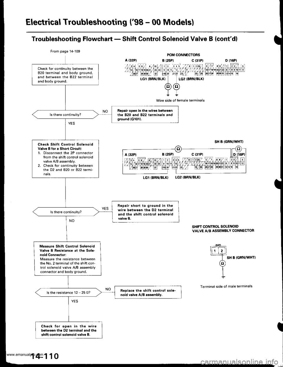
Electrical Troubleshooting ('98 - 00 Models)
Troubleshooting Flowchart - Shift Control Solenoid Valve B {cont'd)
PCM CONNECTORS
a {25P) C t31
I
Wire side of l6male terminals
LG1 IBRN/BLKILG2IBRN/BLKI
SHIFT CONTROL SOLENOIDVALVE A/B ASSEMBLY CONNECTOR
lF-E]
I SH B IGRN/WHTI
(ol
YII
Terminal side of male terminals
From page 14-109
Check for continuity between the820 terminal and body ground,
and between the 822 terminaland body ground.
Repair open in the wire! b€twoenth6 B20 and 822 terminals andground lG101l.
Check Shilt Control SolenoidValve B for a Sho.t Circuit:1, Disconnect the 2P connectorfrom the shift control solenoidvalve !VB assembly.2. Check tor continuity betweenthe D2 and B2O o( 822 tetmi-nals,
Repair short to ground in thewir€ b€twe6n th€ D2 terminaland the shift control solenoidvalve B.
Measu.e Shift Control SolenoidValve B Rasistance at tha Solo-noid Connector:Measure the resistance betweenthe No. 2 terminal of the shift control solenoid valve NB assemblvconnector and body ground.
ReDlac. the shift control sole-noid valve A/B r$embly.ls the resistance 12 25 O?
Check for oDen in the wireb€twoen ths D2 torminal and theshift control 3olenoid valve 8.
A (32P1c 13lPlD tl6Pl
a t32Ptc {31P1
14-110
www.emanualpro.com
Page 638 of 1395
Electrical Troubleshooting {'gB - 00 Models}
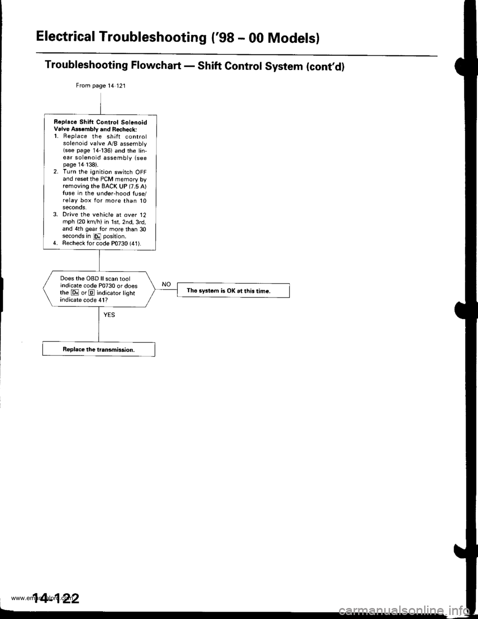
Troubleshooting Flowchart - Shift Control System (cont,d)
From page 14 121
Replace Shilt Cont.ol SolenoidValve A$ambly and Recheck:'1. Replace the shift controlsolenoid valve A/B assembly(see page 14-136) and the lin,ear solenoid assembly (seepage 14138).2. Turn the ignition switch OFFand reset the PCM memory byremoving the BACK UP (7.5 A)tuse in the !nder-hood luse/relay box for more than 10seconos.3. Drive the vehicle at over '12
mph (20 km,/ti) in lst,2nd,3rd,and 4th gear tor more than 30seconds in E position.4. Recheck for code P0730 (41).
Does the OBD ll scan toolindicate code P0730 or doesthe E orE indicator lightindicate code 41?
Tho system is OK .l this tim€.
www.emanualpro.com
Page 652 of 1395
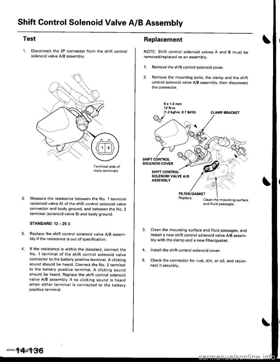
Shift Control Solenoid Valve A/B Assembly
Test
'1. Disconnect the 2P connector from
solenoid valve Ay'B assembly.
the shift control
Terminalsade ofmale terminals
Measure the resistance between the No. 1 terminal(solenoid valve A) of the shift control solenoid valve
connector and body ground, and between the No. 2terminal (solenoid valve B) and body ground.
STANDARD: 12 - 25 O
Replace the shift control solenoid valve A,/B assem-bly if the resistance is out of specification.
lf the resistance is within the standard. connect theNo, I terminal of the shift control solenoid valveconnector to the battery positive terminal. A clickingsound should be heard. Connect the No. 2 terminalto the battery positive te.minal. A clicking soundshould be heard. Replace the shift control solenoidvalve A/B assembly if no clicking sound is heardwhen either terminal is connected to the battervpositive terminal.
14-136
Replacement
NOTE: Shift control solenoid valves A and B must beremoved/replaced as an assembly.
1. Remove the shift control solenoid cover.
2. Remove the mounting bolts, the clamp and the shiftcontrol solenoid valve Ay'B assembly, then disconnect
the connector.
6x1.0mm12 N.m{1.2 k9 .m,8.7 lbtft}CLAMP ARACKET
FILTER/GASKETReplace.Clean the mounling surfaceand fluid passages.
Clean the mounting surface and fluid passages. andinstall a new shift control solenoid valve Ay'B assem-bly with the clamp and a new filter/gasket.
Install the shift control solenoid cover.
Check the connector for rust, dirt. or oil, and recon-nect it securely.
w
SHIFT CONTROLSoLENO|O COVEn
SHIFT CONTROLSOLENOID VALVE A/BASSEMBLY
\--
qK
-!t'">,,
www.emanualpro.com
Page 670 of 1395
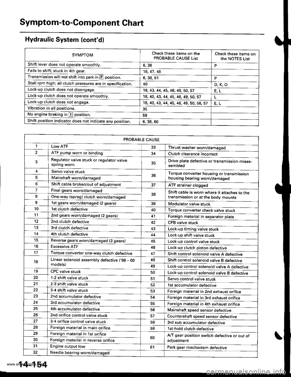
Symptom-to-Component Chart
Hydraulic System (cont'd)
SYMPTOMCheck these items on thePROBABLE CAUSE ListCheck these items onthe NOTES Lisr
Shift lever does not operate smoothly.o, JdPFails to shift; stuck in 4th gear.14, 41 , 48
Transmission will not shift into park in E position.6, 38, 61PStall rpm high; all clutch pressures are in specification.40D,K,OLock-up clutch does not disengage.18, 43, 44, 45, 46, 49,50,57
Lock-up clutch does not operate smoothly.14, 40, 43, 44, 45, 46, 49, 50. 57Lock-up clutch does not engage.'t8, 40, 43, 44, 45, 46, 49, 50, 56, 57Vibration in all positions.
No engine braking in I position.59
Shift position indicator does not indicate anv position,6. 38, 60
PROBABLE CAUSE
I 33 Thrust washer worn/damaged
ATF pump worn or binding34Clutch clearance incorrect
Regulator valve stuck or regulator valvespflng wornDrive plate delective or transmission mtsas-sembled
Servo valve stuck5ttTorque converter housing or transmissionhousing bearing worn/damagedMainshaft worn/damaged
Shift cable broken/out of adjustmentATF strainer clogged
7Final gears worn/damaged38Shift cable is worn where it attaches to thetransmission or at the body mountsIOne-way (sprag) clutch worn/damaged
1st gears worn/damaged {2 gears)39Modulator valve stuck10lst clutch defective40Torque converter check valve stuck112nd gears worn/damaged (2 gears)41Foreign material in separator plate't22nd clutch defectiveCPB valve stuck
t53rd clutch defective43Lock-up timing valve stuck144th clutch defective44Lock-up shift valve stucktcReverse gears worn/damaged (3 gears)Lock-up control valve stuck16Excessive ATF46Lock-up clutch Diston defective17Torque converter one-way clutch defective47Shift control solenoid valve A defecttve
18Linear solenoid assemblv defective (,98 - OOmodels)48Shift control solenoid valve B dsfectrve
49Lock-up control solenoid valve A defective'19CPC valve stuckLock-up control solenoid valve B deleqtve20l-2 shift valve stuck51Servo control valve stuck212-3 shift valve stuck52lst accumulator defective3-4 shift valve stuck53Foreign material in 2nd exhaust orifice2nd accumulator defective54Foreign material in 3rd exhaust orifice3rd accumulator defectiveForeign material in 4th exhaust orifice4th accumulator defective56Mainshaft speed sensor defective262nd orifice control valve stuckCountershaft speed sensor defective273-4 orifice control valve stuck583rd sub accumulator defective2aForeign material in main orifice59lst-hold clutch defective29Foreign material in lst orifice60A/T gear position switch defective or out ofadjustment30Foreign material in reverse orifice
31Engine output low61Park gear mechanism defective32Needle bearing worn/damaged
14-154
www.emanualpro.com
Page 671 of 1395
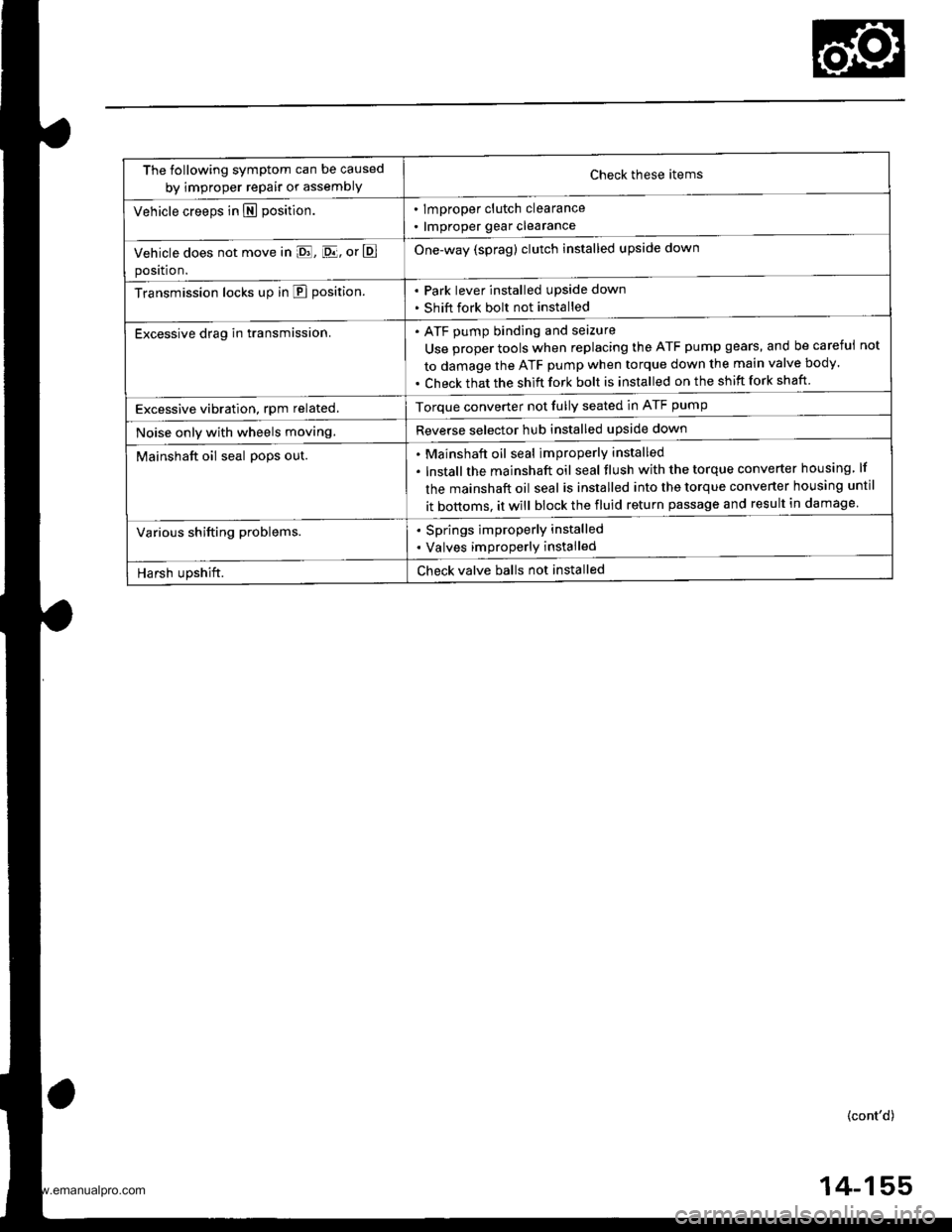
The following symptom can be caused
by improper repair or assemblYCheck these items
. lmproper clutch clearance
. lmproper gear clearance
One-way (sprag) clutch installed upside down
Park lever installed upside down
Shift fork bolt not installed
Vehicle creeps in N position.
Vehicle does not move in E, [D.lj, or E
position.
Transmission locks up in E position.
Excessive drag in transmission.ATF pump binding and seizure
Use proper tools when replacing the ATF pump gears, and be careful
to damage the ATF pump when torque down the main valve body.
Check that the shift fork bolt is installed on the shift fork shaft
not
Excessive vibration, rpm related.Torque converter not fully seated in ATF pump
Reverse selector hub installed upside downNoise only with wheels moving.
Mainshaft oil seal po9s out.Mainshaft oil seal improperly installed
lnstallthe mainshaft oil seal tlush with the torque converter housing lf
the mainshaft oil seal is installed into the torque converter housing until
it bottoms. it will block the fluid return passage and result in damage
Various shifting problems.. Springs improperly installed
. Valves improperly installed
Harsh upshift.Check valve balls not installed
(cont'd)
4-155
www.emanualpro.com