Main relay HONDA CR-V 1999 RD1-RD3 / 1.G Service Manual
[x] Cancel search | Manufacturer: HONDA, Model Year: 1999, Model line: CR-V, Model: HONDA CR-V 1999 RD1-RD3 / 1.GPages: 1395, PDF Size: 35.62 MB
Page 1203 of 1395

Power Distribution
Fuse-to-Gomponent(sl Index (numerical sequence)
Under-hood Fuse/Rolay Box:
41
43
44
46
47
48
49
50
52
Capacity
'100 A
40A
7.5 A
15 A
40A
7.5 A
30A
204
204
15 A
10A
40A
40A
204
20A
Capacity
40A
204
7.5 A
wiro ColorFuseCircuit(s) Prot€cted
A
lgnition switch (BAT)
lntegrated control unit
Ceiling lights
Spotlights
PGM-Fl main relay
Not used
No. 7, 8, 10, 11 fuse in the under-dash fuse/relay box
Audio unit
Clock {'98 - 00 models)
Data link connector ('98 - 00 models)
ECM (VBU) {'98 - 00 models: M/T)
Heater control panel
PCM (VBU) (A./T)
Combination light switch (via under-dash fuse/relay box)
No. 20, 33 fuse in the under-dash fuss/relay box
Not used
Rear window defogger (via relay)
Door lock control unit
Hatch glass opener solenoid
Keyless door lock control unit ('98 - 00 models)
Horn relay
Horns (via relay)
via brake switch:
ABS control unit
Brake lights
Cruise control unit
ECM ('98 - 00 models: M/T)
High mount brake iight
PCM (4./T)
Trailer lighting connector
Turn signal/hazard relay (via switch)
Option connector (+B)
No. 6 fuse in the under-dash fuse/relay box
Blower motor (via relay)
Condenser fan motor (via relay)
Ay'C compressor clutch (via relay)
Radiator fan motor (via relay)
Wire Color Circuitls) Protoct
53
54
50
WHT/BLK
WHT/RED
WHT/BLK
WHT/BLU
WHT/BLU
WHT
WHT/GRN
WHT/GRN
WHT/GRN
WHT/BLK
WHT/RED
BLU/WHT
WHT
RED
BLK/RED
Under-hood ABS Fuss/nehy Box:
Fusg
61WHT
WHT/GRN
BRN/YEL
ABS pump motor {via relay}
ABS control unit
ABS control unit
{cont'd)
23-43
www.emanualpro.com
Page 1204 of 1395

Power Distribution
Fuse
1
3
5
6
7
I
9
10
11
12
13
14
"^
RED/B LU
RED/GRN
WHT/BLK
RED/VVHT
YEUBLK
RED
GRN/BLK
BLU/BLK
YEVBLK
YEUGRN
RED
BLK/YE L
BLK/VVHT
17
7.5 A
7.5 A
BLVBLU
BLKA/EL
18
19
20
22
7.54
7.54
l0 A
10 A
YEUBLK
YEVRED
BLKAr'YHT
RED /VHT
RED/YE L
Fuse-to-Component(sl Index (numerical sequencel (cont'dl
Under-dash Fuse/Relay Box:
Capacity
10 A
10 A
10 A
10 A
20A
204
15A
204
204
7.5 A'15 A
7.5 A
7.5 A
Wire ColorCircuit{s) Protected
Not used
Not used
Rear window washer motor (via switch)
Rear window wiper control unit ('97 model)
Rear window wiper motor
Daytime running rights resister {Canada)
Right headlight {High beam}
Daytime running rights resister (Canada)
High beam indjcator light
Left headlight (High beam)
Rear accessory socket (via relay)
Left rear power window motor (via switch)
Right rear power window motor (via switch)
Distributor (ignition control module)
Front passenger's power window motor (via switch)
Driver's power window motor {via switch)
Power window master switch (power window control unit)
Turn signal/hazard relay (via switch)
PGM-FI main relay
SRS unit (VA)
Cruise control unit (via switch)
Cruise main switch indicator light
Alternator
Charging system light
ELD unit (USA)
EVAP bypass solenoid valve ('98 - 00 models)
EVAP control canister vent shut valve ('98 - 00 models)
EVAP purge control solenoid valve
Primary HO2S
Secondary H02S
VSS
ABS control unit
Option connector (lG2)
Ay'C compressor clutch relay
Blower motor high relay
Blower motor relay
Condenser fan relay
Heater control panel
Left power mirror actuators (via switch)
Mode control motor
Radiator fan relay
Recirculation control motor
Right power mirror actuators (via switch)
Daytime running lights control unit (Canada)
Back-up lights
Reverse relay (A"/T)
Daytime running lights control unit (Canada)
Right headlight (Low beam)
Left headlight (Low beam)
23-44
www.emanualpro.com
Page 1205 of 1395
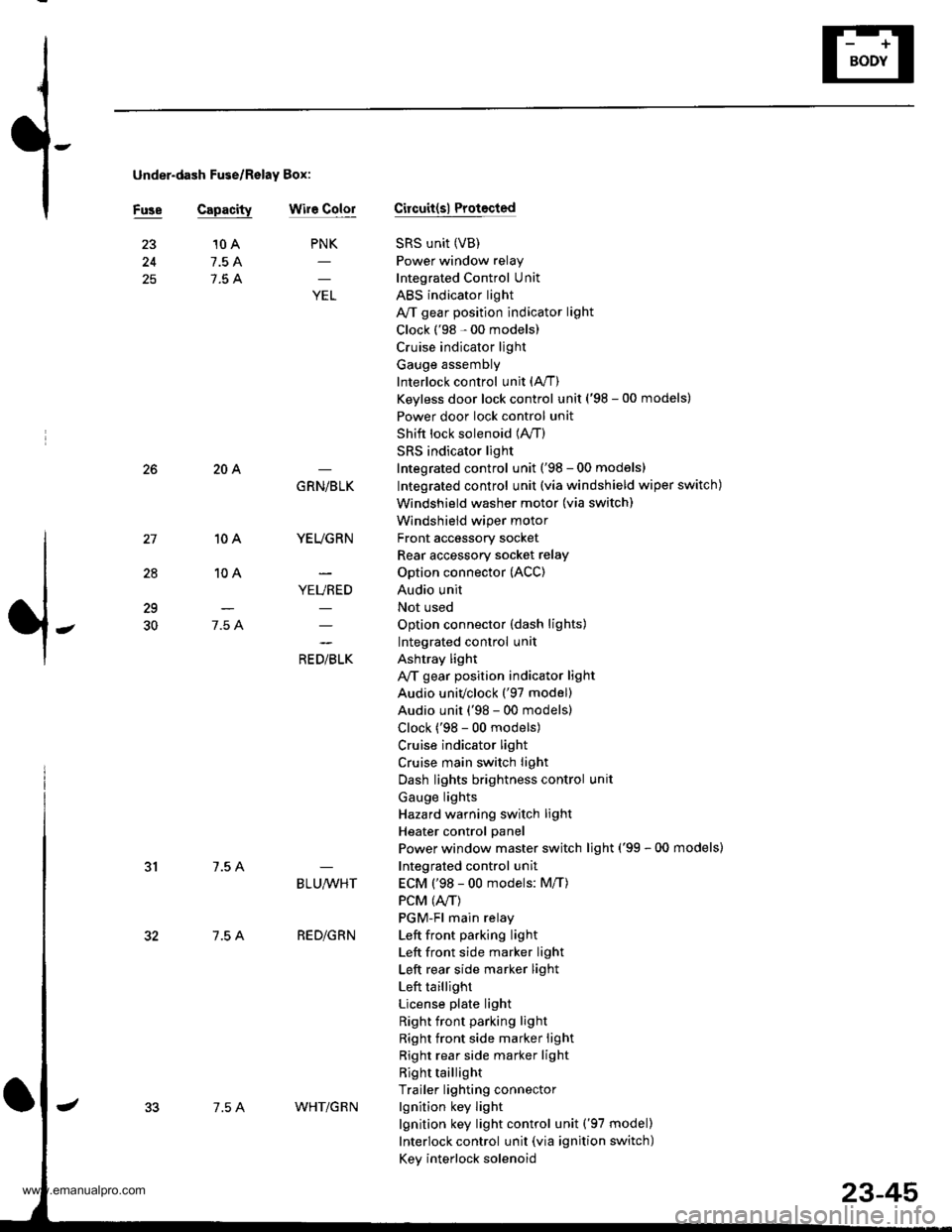
under-dash Fuse/Relay Box:
Fuse Capacitywir6 ColorCircuit(sl Protocted
SRS unit (VB)
Power window relay
Integrated Control Unit
ABS indicator light
A/T gear position indicator light
Clock ('98 - 00 models)
Cruise indicator light
Gauge assembly
Interlock control unit (A,/T)
Keyless door lock control unit ('98 - 00 models)
Power door lock control unit
Shift lock solenoid (lVT)
SRS indicator light
Integrated control unit ('98 - 00 models)
Integrated control unit (via windshield wiper switch)
Windshield washer motor (via switch)
Windshield wiper motor
Front accessory socket
Rear accessory socket relay
Option connector (ACC)
Audio unit
Not used
Option connector (dash lights)
Integrated control unit
Ashtray light
A,/T gear position indicator light
Audio univclock ('97 model)
Audio unit ('98 - 00 models)
Clock ('98 - 00 models)
Cruise indicator light
Cruise main switch light
Dash lights brightness control unit
Gauge lights
Hazard warning switch light
Heater control panel
Power window master switch light ('99 - 00 models)
Integrated control unit
ECM ('98 - 00 models: M/T)
PCM (4./T)
PGM-Fl main relay
Left front pa.king light
Left front side marker light
Left rear side marker light
Left taillight
License plate light
Right front parking light
Right front side marker light
Right rear side marker light
Right taillight
Trailer lighting connector
lgnition key light
lgnition key light control unit ('97 model)
Interlock control unit (via ignition switch)
Key interlock solenoid
25
PNK
;
10 A
7.5 A
7.5 A
28
10A
10A
7.5 A
204
7.5 A
7.5 A
GRN/BLK
YEUGRN
YEURED
a, olrL"
29
30
BLU,ryVHT
RED/GRN
7.5 AWHT/G R N
23-45
www.emanualpro.com
Page 1206 of 1395

Ground Distribution
Ground-to-Component(sl Index
GroundWire Color
G2
G3
G 10'l
G201
G202
G351
BLIVRED
BRN
BLK
BLK
BRN/BLK
BLK
BLK
BLK
23-46
Component or Circuits Grounded
Battery
Valve Cover
Transmission housing
A,/T gear position switch
ECM (PG1, PG2) ('98 - 00 models: M/T)
PCM (PG1, PG2l (Avrr)
PGM-FI main relay
Power steering pressure (PSP) switch
Radiator fan switch
VSS
Data link connector
ECM (1G1, LG2) ('98 - 00 models: M/T)
PCM (LGI, LG2) (IVT)
Shielding:
between ECM ('98 - 00 models: M/T) or PCM (Ay'T) and CKF sensorbetween ECM {'98 - 00 modets: M/T} or pCM (Ay'T) and CKp sensorbetween ECM ('98 - 00 models: M/T) or PCM (rVT) and CYP sensorbetween ECM ('98 - 00 models: M/T) or PCM (Ay'T) and TDC sensorbetween ECM {'98 - 00 models: M/T) or PCM (ly'T) and countershaft speed sensor (Ay'T)
between ECM ('98 - 00 models: M/T) or PCM {A,,/T) and mainshaft sp€ed sensor {!VT)between ECM ('98 - 00 models: M/T) or PCM (A,/T) and primary HO2Sbetween ECM ('98 - 00 models: M/T) or PCM (Ay'T) and secondary HO2SHorn (High)
Horn {Low}
Radiator fan motor
Right headlight
Right front parking light
Right front side marker light
Right front turn signal light
Condenser fan motor
Cruise actuator
Left front parking light
Left front side marker light
Left front turn signal light
Left headlight
Rear window washer motor
Windshield washer motor
ABS pump motor
www.emanualpro.com
Page 1207 of 1395

BLKG401
GroundWir€ ColorComponent or Circuits Grounded
ABS indicator circuit
ABS control unit
Ashtray light
A/T gear position indicator dimming circuit
Brake fluid level switch
Clock ('98 - 00 models)
Clutch inrerlock switch (M/T)
Clutch switch (Mff)
Cruise main switch
Cruise indicator circuit
Cruise control unit
Dash lights brightness controller
Data iink connector
Daytime running rights control unit (Canada)
Front accessary socket
Gauge and indicators
Heater control panel
lgnition key light control unit ('97 model)
lgnition key switch
Integrated control unit
Interlock control unit (Ay'T)
Parking pin switch {A,/T)
Power window relay
Rear accessary socket relay
Bear window defogger relay
Rear window wiper control unit ('97 model)
Service check connector
Spotlights
SRS indicator circuit
Turn signal/hazard relay
Windshield wiper motor
Windshield wiper/washer switch- plus everything grounded through G402
ABS control unit
Blower motor relay
Blower motor high relay
ELD unit (USA)
Power transistor- plus everything grounded through G401
BLKG402
{cont'd)
23-47
www.emanualpro.com
Page 1209 of 1395
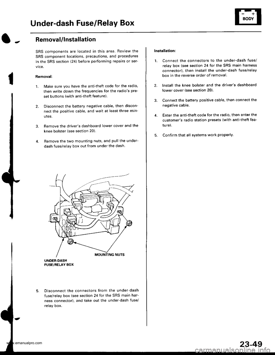
Under-dash Fuse/Relay Box
I
Removal/lnstallation
SRS components are located in this area. Review the
SRS component locations, precautions, and procedures
in the SRS section (241 before performing repairs or ser-
vice.
Removal:
1. Make sure you have the anti-theft code for the radio,
then write down the frequencies for the radio's pre-
set buttons (with anti-theft feature).
2. Disconnect the battery negative cable, then discon-
nect the positive cable, and wait at least three min-
utes.
3. Remove the driver's dashboard lower cover and the
knee bolster (see section 20).
4. Remove the two mounting nuts, and pull the under-
dash fuse/relay box out from under the dash
Disconnect the connectors from the under-dash
fuse/relay box (see section 24 for the SRS main har-
ness connector), and take out the under-dash fuse/
relay oox.
Installation:
1. Connect the connectors to the under-dash fuse/
relay box (see section 24 for the SRS main harness
connector), then install the under-dash lusehelay
box in the reverse order of removal.
2. lnstall the knee bolster and the driver's dashboard
lower cover (see section 20).
3. Connect the battery positive cable, then connect the
negative cable.
4. Enter the anti-theft code for the radio, then enter the
customer's radio station presets (with anti-thett fea-
ture).
5. Confirm that all systems work properly
23-49
www.emanualpro.com
Page 1214 of 1395
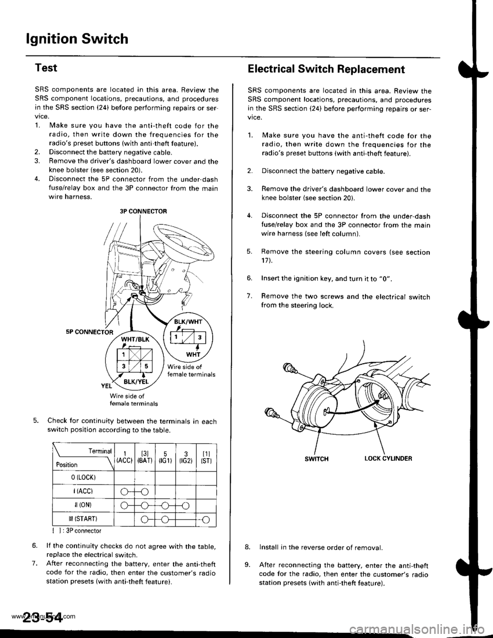
lgnition Switch
Test
SRS components are located in this area. Review the
SRS component locations, precautions, and procedures
in the SRS section {24} before performing repairs or ser
vtce.
L lMake sure you have the anti-theft code for the
radio, then write down the frequencies for theradio's preset buttons (wilh anti-theft feature).
2. Disconnect the battery negative cable.
3. Remove the driver's dashboard lower cover and the
knee bolster {see section 20).
4. Disconnect the 5P connector from the under-dash
fuse/relay box and the 3P connector from the main
wtre narness,
5P CONNECTOR
Wire side oftemale terminals
Check tor continuity between the terminals in eachswitch position according to the table.
rernrnal
ros[ron \
I(ACC)I3l{BAT}5flG1)30G2iI1llsrl
0 (LocK)
r(Acclo--o
fl (oN)G_o
III (START)o--.o
7.
{ I | 3P connector
lf the continuity checks do not agree with the table,replace the electrical switch.
After reconnecting the battery, enter the anti-theftcode for the radio, then enter the customer's radio
station presets (with anti-theft feature).
23-54
3P CONNECTOR
Electrical Switch Replacement
SRS components are located in this area. Review the
SRS component locations, precautions, and procedures
in the SRS section {24) before performing repairs or ser-vice.
1. Make sure you have the anti-thett code for the
radio, then write down the frequencies for the
radio's preset buttons (with anti-theft feature).
2. Disconnect the battery negative cable.
3. Remove the driver's dashboard lower cover and the
knee bolster (see section 20).
4. Disconnect the 5P connector from the under,dash
tuse/relay box and the 3P connector f.om the main
wire harness {see left column).
7.
Remove the steering column covers (see section'17 t.
Insert the ignition key, and turn it to "0".
Remove the two screws and the electrical switchfrom the steering lock,
swrTcHLOCK CYLINDER
lnstall in the reverse order of removal.
After reconnecting the battery, enter the anti-theftcode for the radio, then enter the customer's radiostation presets (with antj-theft feature).
9.
www.emanualpro.com
Page 1313 of 1395
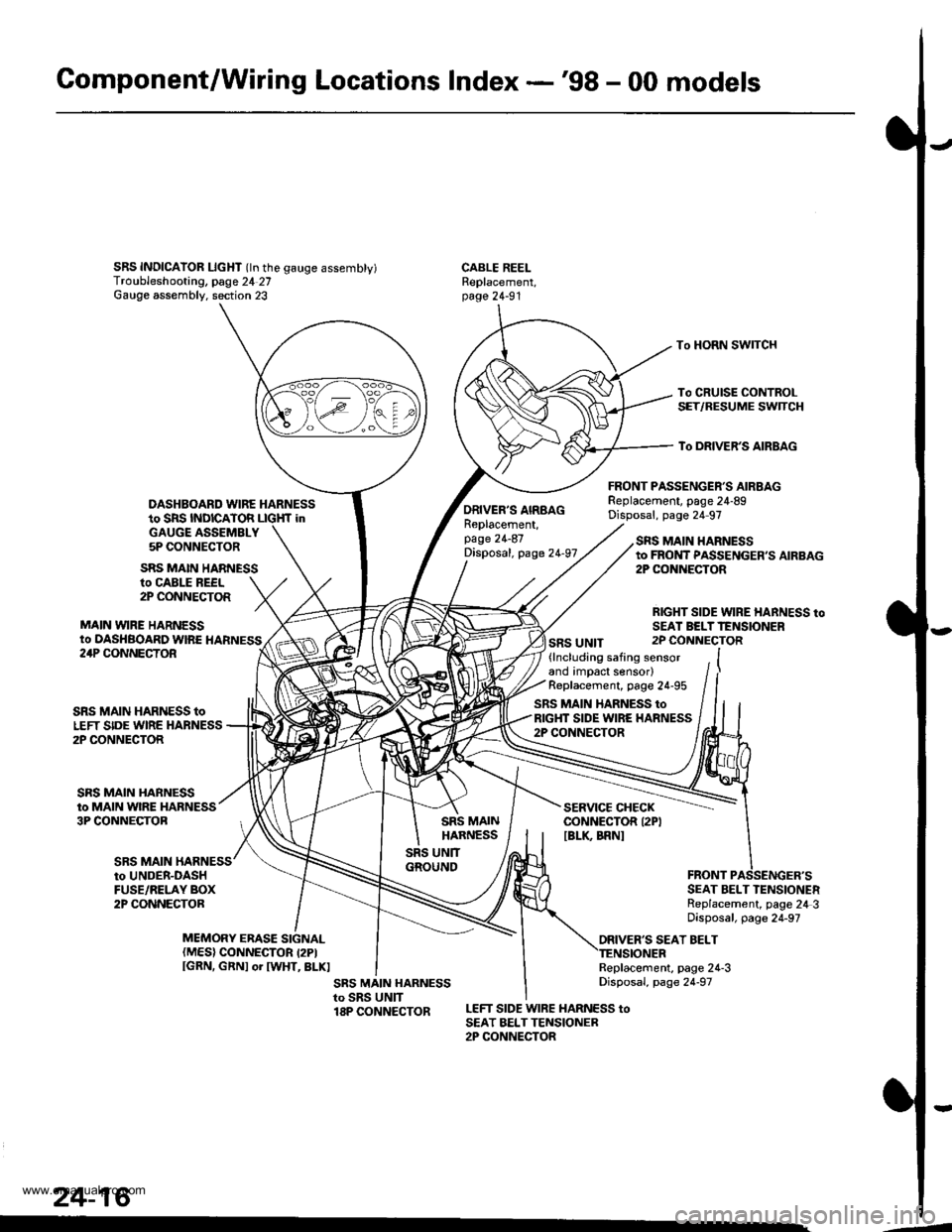
Gomponent/Wiring Locations Index -'98 - 00 models
SRS INDICAIOR LIcHT (ln the gauge assembty)Troubleshooting, page 24 27Gauge assembly. section 23
DASHBOARD WIRE HARNESSto SRS INDICATOR LIGHf inGAUGE ASSEMBLY5P CONNECTOR
FRONT PASSENGER'S AIRBAGReplacement, page 24-89Disposal, page 24 97
CABLE REELReplacement,page 24-91
To HORN SWITCH
To CRUISE CONTROLSET/RESUME SWTCH
To DRIVER'S AIRBAG
ro CABLE REEL2P CONNECTOR
MAIN VYIRE HARNESSto DASHBOARD WIRE HARNESS
SRS MAIN HARNESS
ORIVER'S AIRBAGReplacement,page 24-87Disposal, page 24-97
SRS UNIT
SRS MAIN HARNESSto FROI{T PASSENGER,S AIRBAG2P CONiIECTOR
RIGHT SIDE WIRE HARNESS toSEAI BELTTENSIONER2P CONNECTOR24P CONNECTOR
SRS MAIN
SRS MAIN HARNESS toLEFT SIDE WIRE HARNESS2P CONNECTOR
SRS MAIN HARNESSto MAIN WIRE HARNESS3P CONNECTOB
(lncluding safing sensorand impact sensor)Replacement, page 24-95
SRS MAIN HARNESS toRIGHT SIDE WIRE HARNESS2P CONNECTOR
SERVICE CHECKCONNECTOR I2PIIBLK BRNI
to UNDER-DASHFUSE/RELAY BOX2P CONNECTORSEAT BELT TENSIONERReplacement, page 24 3Disposal, page 24-97
ORIVER'S SEAT BELTMEMORY ERASE SIGNAL(MES) CONNECTOR I2PIIGRN, GRNI or IWHT, BLKIReplacement, page 24-3Disposal, page 24-97
LEFT SIDE WIRE HARNESS toSEAT BELTTENSIONER2P CONNECTOR
24-16
.4
www.emanualpro.com
Page 1315 of 1395
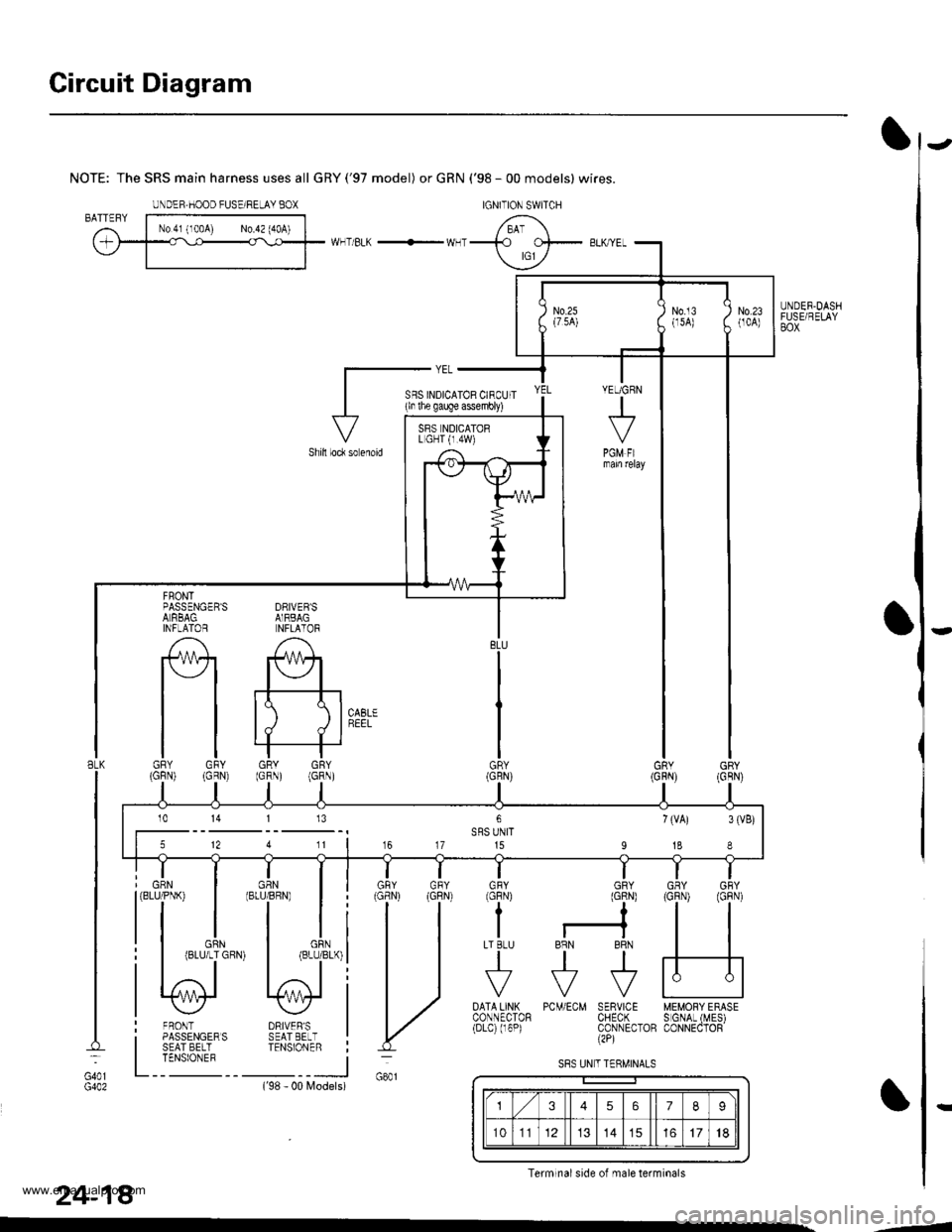
Circuit Diagram
UNDER.DASHFUSE/RELAYBOX
NOTE: The SRS main harness uses all GRY('97 model) or GRN ('98 - 00 models) wires.
WHT/BLK -'- WHT
DRIVEB'SAIRBAGNFLATOR
A
#+
tt tll./ d I
GRY GRY(GRN) (GRN)
FRONTPASSENGER'SALRBAGINFLAlOR
tlGRY GFY(GFN) (GRN)
DRIVER'SSEAT EELTTENSIONER
FRONTPASSENGERSSEAT BELTTENSIONEF
GRN(BLU/PNK)
BLK
G401
24-18
PCM/ECM SERVICE MEMORY ERASECHECK S GNAL (MES)CONNECTOB CONNECTOR(2P)
DATA LINXCONNECTOR(Drc) (r6P)
Models)('98 - 00
IGNITION SWITCHUNDEF,HOOD FUSE/RELAY BOX
YEUGRN
+
PGM FImam relay
SFS INDICATOR CIRCUIT(ln lhe gauge assembly)
Shill loc* so enoid
BLU
GR\
GNY GRY
H
GFY GRYlcFNt (GlN)
??
I r-?LT BLU BRN BRN
tttr?F?F
VVV
SRS NDICATORL GHT {r.4W)
5 12 4 11 | 16 17 15 I 18 I
10 14 113
U
S8S UN T TERMINALS
3567I
101114151718
Terminal side of male terminals
-4
www.emanualpro.com
Page 1322 of 1395
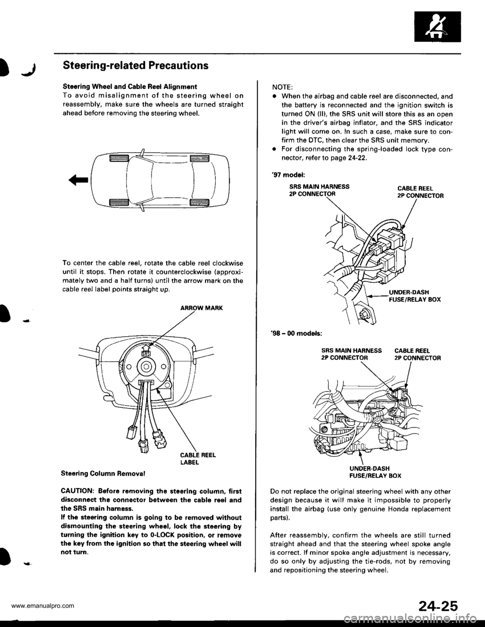
)Steering-related Precautions
Stooring Wh€el and Csble Re6l Alignm€nt
To avoid misalignment of the steering wheel on
reassembly, make sure the wheels are turned straight
ahead beJore removing the steering wheel.
To center the cable reel, rotate the cable reel clockwise
until it stops, Then rotate it counterclockwise (approxi-
mately two and a half turns) until the arrow mark on the
cable reel label points straight up.
Steering Column Bemoval
CAUTION: Before removing the stosring column, tirsi
disconneqt tha connsctor between tho cabls roel and
the SRS main harness.
lf the steering column is going to be removed without
dismounting the steering wheel, lock the sieering by
turning the ignition key to o-LOCK position, or remove
the key trom the ignition so that the steering wheel will
not turn.
LABEL
NOTE:
. When the airbag and cable r6el are disconnected, and
the battery is reconnected and the ignition switch is
turned ON (ll), the SRS unit will store this as an open
in the driver's airbag inflator, and the SRS indicator
light will come on, In such a case, make sure to con-
firm the DTC, then clear the SRS unit memory.
. For disconnecting the spring-loaded lock type con-
nector, refer to page 24-22.
'97 model:
SRS MAIN HARNESS2P CONNECTORCABLE REEL2P CONNECTOR
'98 - 00 models:
UNDER-DASHFUSE/RELAY BOX
Do not replace the original steering wheel with any other
design because it will make it impossible to properly
install the airbag (use only genuine Honda replacement
partsl.
After reassemblv, confirm the wheels are still turned
straight ahead and that the steering wheel spoke angle
is correct. lf minor spoke angle adjustment is necessary,
do so only by adjusting the tie-rods, not by removing
and repositioning the steering whee .
24-25
www.emanualpro.com