Mounting HONDA CR-V 1999 RD1-RD3 / 1.G Repair Manual
[x] Cancel search | Manufacturer: HONDA, Model Year: 1999, Model line: CR-V, Model: HONDA CR-V 1999 RD1-RD3 / 1.GPages: 1395, PDF Size: 35.62 MB
Page 892 of 1395
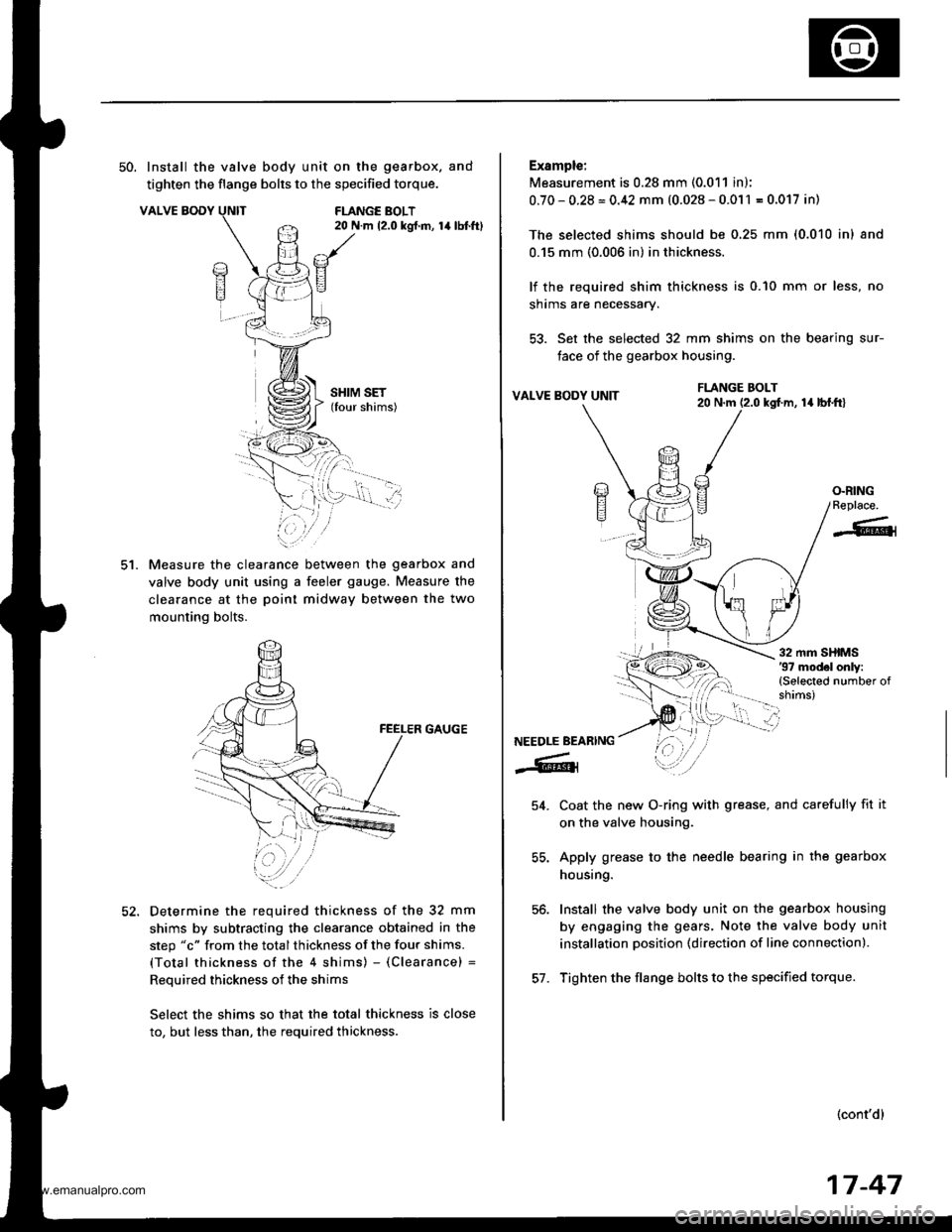
50. Install the valve body unit on the gearbox. and
tighten the flange bolts to the specified torque.
VALVE BODYFLANGE BOLT20 N.m 12.0 kgt.m, 14lbtft)
ct.
SHIM SET(four shims)
Measure the clearance between the gearbox and
valve body unit using a feeler gauge. Measure the
clearance at the poinl midway between the two
mounting bolts.
GAUGE
Determine the required thickness of the 32 mm
shims by subtracting the clearance obtained in the
step "c" from the total thickness of the four shims.
(Total thickness of the 4 shims) - (Clearance) =
Reouired thickness of the shims
Select the shims so that the total thickness is close
to, but less than, the required thickness.
Example:
Measurement is 0.28 mm (0.011 in);
0.70-0.28=0.42 mm (0.028-0.011 = 0.017 in)
The selected shims should be 0,25 mm (0.010 inl and
0.15 mm (0.006 in) in thickness.
lf the required shim thickness is 0.10 mm or less, no
shrms are necessary.
53. Set the selected 32 mm shims on the bearing sur-
face of the gearbox housing.
VALVE BODY UNITla lbl.frl
Coat the new O-ring with grease, and carefully fit it
on the valve housing.
Apply grease to the needle bearing in the gearbox
housing.
Install the valve body unit on the gearbox housing
by engaging the gears. Note the valve body unit
installation position (direction of line connection).
Tighten the flange bolts to the specified torque.
(cont'd)
FLANGE BOLT20 N.m (2.0 kgf.m,
/a)E?
E
O.RINGReplace.
-6{
NEEDLE BEARING
-6lr
54.
56.
57.
17-47
www.emanualpro.com
Page 896 of 1395
lnstallation
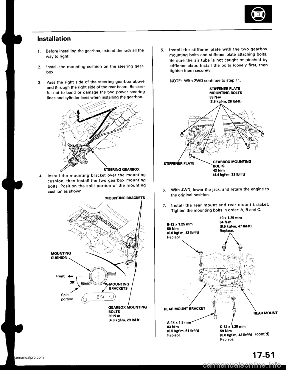
1. Before installing the gearbox, extend the rack all the
waY to right.
2. lnstall the mounting cushion on the steerlng gear-
box.
3. Pass the right side of the steering gearbox above
and through the right side of the rear beam. Be care-
ful not to bend or damage the two power steering
STEERING GEARBOX
Install the mounting bracket over the mounting
cushion. then install the two gearbox mounting
bolts. Position the split portion of the mounting
cushion as shown.
MOUNTING BBACKETS
GEARBOX MOUNTINGBOLTS39 N.m14.0 kgf.m, 29 lbf.ft)
:-
/
5. Install the stiffener plate with the two gearbox
mounting bolts and stiffener plate attaching bolts.
Be sure the air tube is not caught or pinched by
stiffener plate. Install the bolts loosely first. then
tighten them securely.
NOTE: With 2WD continue to step 11.
STIFFENER PLATEMOUNTING BOLTS38 N.m
1.
With 4WD, lower the iack, and return the engine to
the original Position.
lnstall the rear mount and rear mount bracket.
Tighten the mounting bolts in order: A, B and C.
8.12 x 1,25 mm
59 N.m(6.0 kgt.m. *l lb{'ftlReplace.
10 x 1.25 mm6,a N.m
16.5 kst.m, 47 lbl'ft)R€place.
)\^
o(]
17-51
www.emanualpro.com
Page 897 of 1395
Power Steering Gearbox
Installation (cont'd)
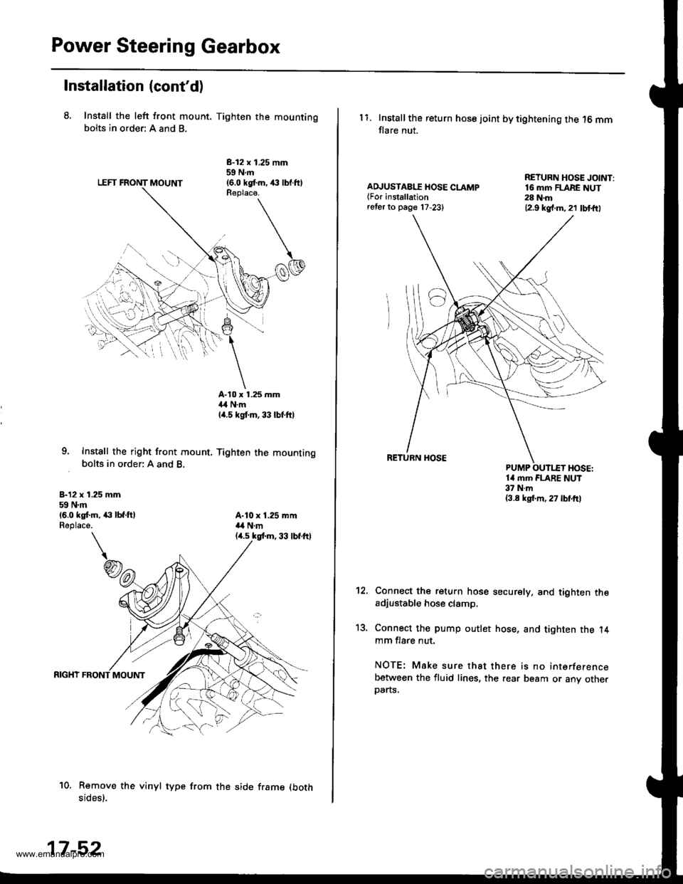
8, Install the left front mount. Tighten the mountingbolts in order: A and B.
LEFT FRONT MOUNT
B-12 x 1,25 mm59Nm(6.0 kgtm,,€ lbl.ftlReplaca.
9. Instsll the right front mount, Tighten the mountingbolts in order: A and B.
B-12 x 1.25 mm59 N.m16.0 ks[.m, ,|:| lbf.ftlReplace.
A-10 x 1.25 mm4,1 N.mla.s kgt m, 33 lbf.ft)
A-10 x 1.25 mma,a N.m
10. Remove the vinyl type from the side frame (both
sides).
17-52
11. Installthe return hose joint by tightening the 16 mmflare nut.
AD.'USTAB[T HOSE CLAMP(For installationreter to page 17,23)
RETURN HOSE JOINT:16 mm FLARE NUT28 N.m12.9 kg{.m.21 lbt{t)
14 mm FLARE NUT37 N.m(3.8 ksf.m, 27 lbl'frl
't2.
13.
Connect the return hose securely. and tighten theadjustable hose clamp.
Connect the pump outlet hose, and tighten the l4mm flare nut.
NOTE: Make sure that there is no interferencebetween the fluid lines, the rear beam or any otherparts.
www.emanualpro.com
Page 906 of 1395
Front Suspension
Suspension Arms Replacement
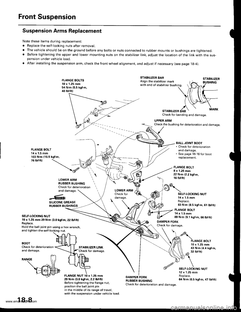
Note these items during replacement:
. Replace the self-locking nuts after removal.
. The vehicle should be on the ground before any bolts or nuts connected to rubber mounts or bushings are tightened.. Before tightening the upper and lower mounting nuts on the stabilizer link, adjusr the location of the link with the sus-pension under vehicle load.
. After insta lling the suspension arm, check the front wheel alignment, and adjust if necessary (see page 18-4|.
FLANGE EOLTS10 x 1.25 mm54 N.m (5.5 kgf.m,40 tbf.ft)
STABILIZER LINKCheck for daftage.
FLANGE BOLT8 x 1.25 mm22 N.m {2.2 kg{.m,16 tbf.ftl
STAEILIZER
AOLT
STABILIZER BARAlign the stabilizer markwith end of stabilizer bushing.
STABILIZERCheck for bending and damage.
UPPER ARMCheck the bushing for deterioration and damage.
FLANGE BOLT1{ x 1.5 mm103 N.m {10.5 kgf.m,76 tbf.ft)
BALL JOINT BOOT. Check for deter'orationano oamage,See page 18 16 for bootreplacement.
LOWER ARMRUBBER BUSHINGCheck for deteriorationand damage.
..'.{l@3
SILICONE GREASERUBBER BUSHINGS
SELF-LOCKING NUT10 x 1.25 rr|m 29 N.m (3.0 kgf.m, 22 lbf.ft)Feplace.Hold the ball ioint pin using a hex wrenct
BOOTCheck for deteriorationano oamage,
29 N.m {3.0 kgl.m, 2.2 lbf.ftlBefore tightening the llange nut,position the ballioint pinin the middle of its range of travel,with the suspension under vehicle load.
DAMPER FORKRUBBER BUSHINGCheck for deterioration and damage.
o\
DAMPER FOBKCheck for damage.
SELF.LOCKING NUT14 x 1.5 mmReplace.83 N.m (8.5 kgt.m, 61 lbt.ftl
FLANGE BOLT14 x 1.5 mm89 N.m (9.'l kgl.m, 66 tbf.ft)
10 x 1.25 mm!$ N.m (4.4 kgt.m,32 rbf.ftl
SELF.LOCKING NUT12 x 1.25 mmBeplace.64 N.m (6.5 kgt.m, 47 lbf.ft)
18-8
www.emanualpro.com
Page 907 of 1395
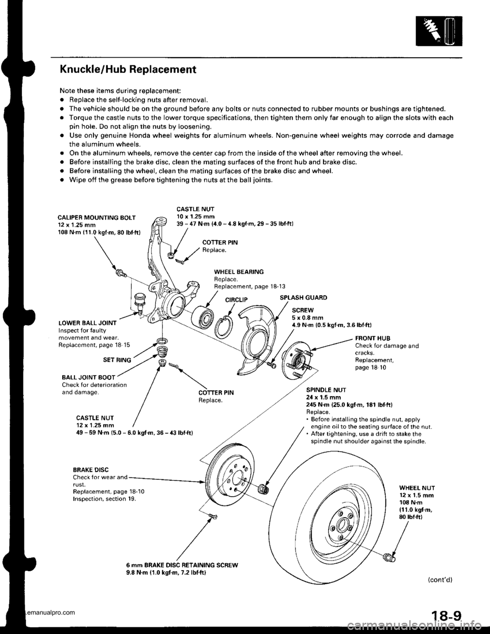
Knuckle/Hub Replacement
Note these items during replacement:
. Replace the selt-locking nuts after removal.
. The vehicle should be on the ground before any bolts or nuts connected to rubber mounts or bushings are tightened.
. Torque the castle nuts to the lower torque specifications, then tighten them only far enough to align the slots with each
pin hole. Do not align the nuts by loosening.
o Use only genuine Honda wheel weights for aluminum wheels. Non'genuine wheel weights may corrode and damage
the aluminum wheels.
. Onthealuminum wheels, remove the center cap from the inside of the wheel after removing the wheel.
. Before installing the brake disc, clean the mating surfaces of the front hub and brake disc.
. Before installing the wheel. clean the mating surfaces ofthe brake disc and wheel.
. Wipe off the grease before tightening the nuts at the balljoints.
CALIPER MOUNTING BOLT12 x 1.25 mm108 N.m (11.0 kgtm.80 lbt.ftl
LOWER BALL JOINTInspect for faultymovement and wear,Replacement, page'18 15
CASTLE NUT10 x 1.25 mm39 - 47 N.m (i1.0 - 4.8 kgf.m, 29 - 35 lbf.ftl
COTTER PINReplace.
WHEEL BEARINGBeplace.Replacement, page 18-13
CIRCLIPSPLASH GUARD
SCREW5x0.8mm4.9 N.m {0.5 kgf.m,3.6lbf.ft)
SET RING
FRONT HUBCheck for damage and
Replacement,page 18 10
BALL JOINT BOOTCheck for deteriorationano oamage.SPINOLE NUT24 x 1.5 mm245 N.m {25.0 kgI.m, 181 lbtft}Replace.. Before installing the spindle nut, applyengine oil to the seating surface of the nut.. After tightening, use a drift to stake thespindle nut shoulder against the spindle.
COTTER PINReplace.
CASTLE NUT12x 1.25 fim49 - 59 N.m 15.0 - 6.0 kgt.m. 36 - € lbf.ft)
BRAKE DISCCheck for wear andrust.Replacement, page 18-10Inspection, section 19.
WHEEL NUT12 x 1.5 mm108 N.m{11.0 kgt m,80 tbf.ftl
6 mm BRAKE DISC RETAINING SCREW9.8 N.m (1.0 kgtm, 7.2 lbtftl(cont'd )
18-9
www.emanualpro.com
Page 908 of 1395
Front Suspension
Knuckle/Hub Replacement (cont'dl
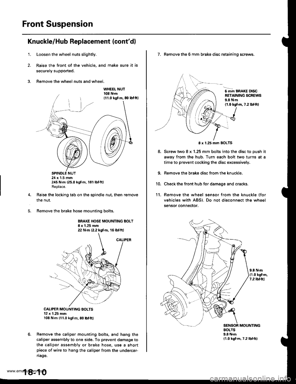
1.Loosen the wheel nuts slightly.
Raise the front of the vehicle, and make sure it is
secu.ely supported.
Remove the wheel nuts and wheel.
SPINDLE NUT24 x 1,5 mm245 N.m (25.0 kgf.m, 181 lbtft)Replace.
Raise the locking tab on the spindle nut, then remove
the nut.
Remove the brake hose mounting bolts.
BRAKE HOSE MOUNTING BOLT8 x 1.25 mm22 N.m {2.2 kgt m, 16 lbtft)
CALIPER MOUNTING BOLTS12 x 1.25 mm108 N.m (11.0 kgl.m, 80 lbl.ft)
Remove the caliper mounting bolts, and hang the
caliper assembly to ona side. To prevent damagg to
the caliper assembly or brake hose, use a shortpiece of wire to hang the caliper from the undercar-
riage.
18-10
7. Remove the 6 mm brake disc retaining screws,
6 mm BRAKE DISCRETAINING SCREWS9.8 N.m(1.0 kgl.m,7.2 lbf.ftl
8.
8 x 1.25 mm BOLTS
Screw two 8 x 1.25 mm bolts into the disc to push it
awav from the hub. Turn each bolt two turns at a
time to prevent cocking the disc excessively,
Remove the brake disc from the knuckle.
Check the front hub for damage and cracks.
11. Remove the wheel sensor from the knuckle (for
vehicles with ABS). Do not disconnect the wheel
sensor connector.
9.8 N.m(1.0 kgf.m,7.2 tbttrl
MOUNTINGBOLTS9.8 N.mlr.0 kgf.m, ?.2lbf.ftl
www.emanualpro.com
Page 913 of 1395
'1.
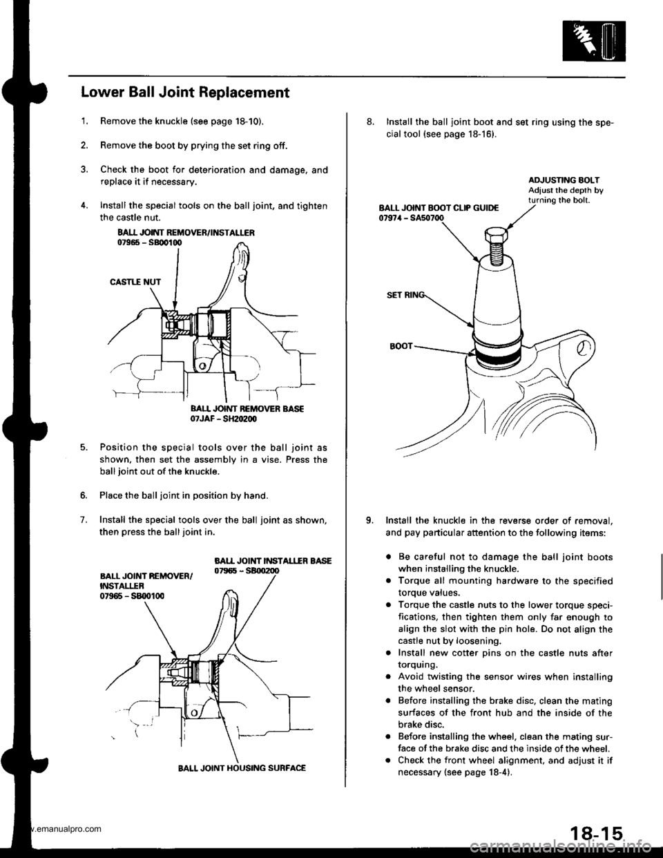
Lower Ball Joint Replacement
Remove the knuckle (see page 18-10).
Remove the boot by prying the set ring off.
Check the boot for deterioration and damage. and
replace it if necessary.
lnstall the special tools on the ball joint, and tighten
the castle nut.
BAII JOINT BEMOVER BASE07JAF - SH2oe00
Position the special tools over the ball joint as
shown. then set the assembly in a vise. Press the
ball joint out of the knuckle.
Place the ball joint in position by hand.
Install the special tools over the ball joint as shown,
then press the balljoint in.
BAII JOINT INSTAL1IR BASE
7.
8AI.I JOINT REMOVEN/INSTALLER
BALL JOINT HOUSING SURFACE
18-15
8. Install the ball joint boot and set ring using the spe-
cial tool {see page 18-16}.
Install the knuckle in the reverse order of removal.
and pay particular attention to the following items:
. Be careful not to damage the ball joint boots
when installing the knuckle.
. Torque all mounting hardware to the specified
toroue values.
a Torque the castle nuts to the lower torque speci-
fications, then tighten them only far enough to
align the slot with the pin hole. Do not align the
castle nut by loosening.
. Install new cotter pins on the castle nuts after
IOrqurng.
Avoid twisting the sensor wires when installing
the wheel sensor.
Before installing the brake disc, clean the mating
surfaces of the front hub and the inside of the
brake disc.
Before installing the wheel. clean the mating sur-
face of the brake disc and the inside of the wheel.
Check the front wheel alignment, and adjust it if
necessary (see page 18-4).
o
www.emanualpro.com
Page 915 of 1395
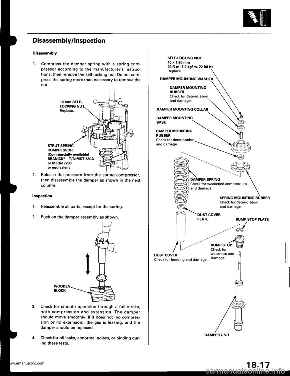
Disassembly/ Inspection
Disass.mbly
1. Compress the damper spring with a spring com-
pressor according to the manufacturer's instruc-
tions, then remove the self-locking nut. Do not com-press the spring more than necessary to remove the
nur.
10 mm SELF-LOCKINGReplace.
STRUTCOMPRESSOR:lComm6rcially availablo)BRANICK@ T/N MST-580Aor Mod6l 7200or equivalent
Release the pressure from the spring compressor,
then disassemble the damper as shown in the next
cotumn.
Inspection
1.Reassemble all parts, except for the spring.
Push on the damper assembly as shown.
Check for smooth operation through a full stroke,
both compression and extension. The damper
should move smoothly. lf it does not (no compres-
sion or no extension), the gas is leaking, and the
damper should be replaced.
Check for oil leaks, abnormal noises, or binding dur-
ing these tests.
2.
29 N.m (3.0 kgl.m,22lbtftlReplace.
DAMPER MOUNTING WASHER
DAMPER MOUNTING
SELF-LOCKING NUT10 x 1.25 mm
RUBBERCheck forano oamage.
DAMPER MOUAMNG COLLAR
DAMPER MOUNTINGBASE
DAMPER MOUNTINGRUBBERCheck for det€riorationano oamage.
BUMP STOP PLATE
DUSTCheckfor bending and damage.
..rgBUMPSTOP g
weakness anddamage,
SPRING MOUNTING
www.emanualpro.com
Page 916 of 1395
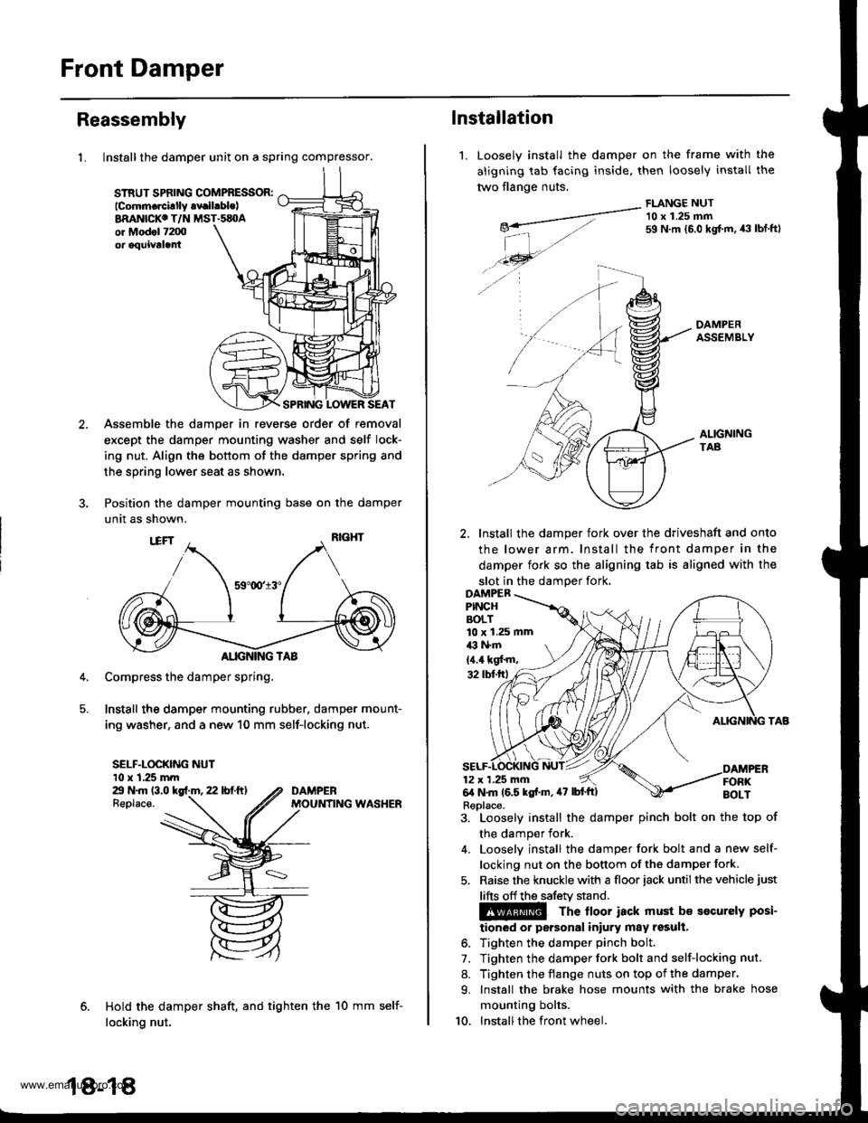
Front Damper
Reassembly
1. Install the damper unit on a spring compressor.
STRUT SPflNG COMPBESSOR:lcomm.rcillly .vrilrble)BRANICKC T/N MST.sEOAor Mod.l 7200or oquivtla
SPRING LOWER SEAT
Assemble the damper in reverse order of removal
except the damper mounting washer and self lock-
ing nut. Align the bottom of the damper spring and
the spring lower seat as shown.
Position the damper mounting base on the damper
unit as shown.
Compress the damper spring,
Install the damper mounting rubber, damper mount-
ing washer, and a new 10 mm self-locking nut.
SELF-LOCKING NUT10 x 1.25 mmZt N.m 13.0 kgf.m, 22 lbf.ft)Replace.
Hold the damper shaft, and tighten the
locking nut.
DAMPERMOUNfING WASHER
18-18
10 mm self-
1.
lnstallation
Loosely install the
aligning tab facing
two flange nuts.
damper on the frame with
inside, then loosely install
FLANGE NUT
the
tne
-__---a-"- 10 x 1.25 mmg*- 59 N.m {5.0 kgt m, 43 tbf.ftl
| -,./.46- --...
./ -4 A-
DAMPERASSEMBLY
ALIGNINGTAB
2, Install the damper fork over the driveshaft and onto
the lower arm. Install the front damper in the
damper fork so the aligning tab is aligned with the
slot in the damDer fork,
3. Loosely install the damper pinch bolt on the top of
the damper fork.
4. Looselv install the damper fork bolt and a new self-
locking nut on the bottom of the damper fork.
5. Raise the knuckle with a floor iack until the vehicle just
lifts off the safetv stand.
The lloor iack must b€ socurely posi-
tioned or personal iniury may result.
6. Tighten the damper pinch bolt.
7. Tighten the damper fork bolt and self-locking nut.
8. Tighten the flange nuts on top of the damper.
9. Install the brake hose mounts with the brake hose
mounting bolts.
10. Installthe front wheel.
10 x 1.25 mmil3 l+m
{4.4 kgf'm,
Replace.
www.emanualpro.com
Page 921 of 1395
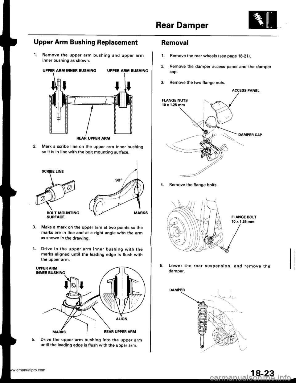
Rear Damper
1.
Upper Arm Bushing Replacement
Remove the upper arm bushing and upper arminner bushing as shown.
UPPER ARM INNER BUSHING UPPER ARM AUSHIT{G
Mark a scribe line on the upper arm inner bushing
so it is in line with the bolt mounting surface.
BOLT MOUNTII{GSURFACE
Make a mark on the upper arm at two points so the
marks are in line and at a right angle with the arm
as shown in the drawing.
Drive in the upper arm inner bushing with themarks aligned until the leading edge is flush with
the uoDer arm.
Drive the upper arm bushing into the upper armuntil the leading edge is flush with the upper arm.
REAR UPPER ARM
5.
Removal
Remove the rear wheels (see page '18-21),
Remove the damper access panel and the damper
cap.
Remove the two flange nuts.
ACCESS PANEL
OAMPER CAP
't.
4. Remove the flange bolts.
Lower the rear suspension, and remove
damper.the
1a-23
www.emanualpro.com